AudioCodes Mediant 2000 System User Manual
Sip, mediant media gateways & trunkpack blades
Hide thumbs
Also See for Mediant 2000 System:
- User manual (702 pages) ,
- Installation manual (44 pages) ,
- Hardware installation manual (30 pages)
Table of Contents
Advertisement
Quick Links
Advertisement
Table of Contents

Subscribe to Our Youtube Channel
Related Manuals for AudioCodes Mediant 2000 System


Summary of Contents for AudioCodes Mediant 2000 System
- Page 1 User's Manual Version 5.2 Document #: LTRT-68806 September 2007...
-
Page 3: Table Of Contents
SIP User's Manual Contents Table of Contents Overview ......................15 SIP Overview ......................15 Mediant 2000 Overview ..................15 TP-1610 Overview ....................17 TP-260 Overview ....................18 Physical Description ..................19 Mediant 2000 Physical Description ................ 19 2.1.1 Mediant 2000 Chassis .....................20 2.1.2 Power Supply......................20 2.1.3... - Page 4 Mediant 2000 & TP-1610 & TP-260/UNI Getting Started ....................47 Configuration Concepts..................47 Startup Process...................... 48 Assigning an IP Address ..................50 4.3.1 Assigning an IP Address Using HTTP..............50 4.3.2 Assigning an IP Address Using BootP ..............51 4.3.3 Assigning an IP Address Using the CLI..............51 4.3.3.1 Accessing the CLI ...................
- Page 5 SIP User's Manual Contents 5.5.5 Configuring the Profile Definitions ................ 132 5.5.5.1 Coder Group Settings................133 5.5.5.2 Tel Profile Settings ................134 5.5.5.3 IP Profile Settings.................. 136 5.5.6 Configuring the Trunk Group Table ..............138 5.5.7 Configuring the Trunk Group Settings ..............140 5.5.8 Configuring the Digital Gateway Parameters ............
- Page 6 Mediant 2000 & TP-1610 & TP-260/UNI 5.11.6 Channel Status ..................... 236 5.11.6.1 Viewing Trunk Port Settings..............237 5.11.6.2 Assigning a Port Name................238 5.11.6.3 Viewing Channel Information ..............239 5.12 Software Update ....................240 5.12.1 Software Upgrade Wizard..................240 5.12.2 Automatic Update Mechanism................245 5.12.3 Auxiliary Files......................
- Page 7 SIP User's Manual Contents 6.5.12 Number Manipulation and Routing Parameters ........... 318 6.5.13 Channel Parameters..................... 332 6.5.14 Configuration Files Parameters ................337 Telephony Capabilities ...................339 Configuring the DTMF Transport Types............... 339 Fax and Modem Capabilities................340 7.2.1 Fax/Modem Operating Modes ................340 7.2.2 Fax/Modem Transport Modes ................
- Page 8 8.4.1 Point-to-Point Protocol (PPP) Overview ............... 369 8.4.2 PPPoE Overview ....................370 8.4.3 PPPoE in AudioCodes gateway ................370 IP Multicasting...................... 371 Robust Reception of RTP Streams ..............371 Multiple Routers Support..................371 Simple Network Time Protocol Support ............... 372 IP QoS via Differentiated Services (DiffServ)............
- Page 9 SIP User's Manual Contents List of Figures Figure 1-1: Mediant 2000 Typical Application ..................16 Figure 2-1: Mediant 2000 Front Panel....................19 Figure 2-2: Front View of TP-1610 cPCI Blade ..................21 Figure 2-3: RTM-1610 Rear Panel with two 50-pin Connectors for 16 Trunks ........24 Figure 2-4: RTM-1610 with 8 RJ-48c Connectors for 8 Trunks .............24 Figure 2-5: TP-260 Board Description....................25 Figure 2-6: RJ-45 Connector Pinouts.....................27...
- Page 10 Mediant 2000 & TP-1610 & TP-260/UNI Figure 5-33: Voice Settings Screen..................... 166 Figure 5-34: Fax / Modem / CID Settings Screen ................168 Figure 5-35: IPmedia Settings Screen ....................176 Figure 5-36: General Media Settings Screen ..................177 Figure 5-37: CAS State Machine Table Screen .................. 192 Figure 5-38: TDM Bus Settings Screen....................
- Page 11 SIP User's Manual Contents List of Tables Table 2-1: Mediant 2000 Front View Component Descriptions..............20 Table 2-2: Chassis LEDs Description.....................20 Table 2-3: Front and Upper View of the TP-1610 cPCI Blade Component Descriptions ......22 Table 2-4: Status LEDs Description .......................22 Table 2-5: E1/T1 Trunk Status LEDs Description ..................22 Table 2-6: Ethernet LEDs Description....................23 Table 2-7: cPCI LEDs Description......................23...
- Page 12 Mediant 2000 & TP-1610 & TP-260/UNI Table 5-39: TDM Bus Settings Parameters..................195 Table 5-40: Internal Firewall Parameters .................... 201 Table 5-41: General Security Settings Parameters................207 Table 5-42: IPSec SPD Table Configuration Parameters ..............211 Table 5-43: Default IKE Second Phase Proposals ................212 Table 5-44: IKE Table Configuration Parameters ................
-
Page 13: Customer Support
SIP User's Manual Notices Notice This document describes the AudioCodes Mediant 2000 SIP gateway, TP-1610 SIP cPCI blade, and TP-260 SIP PCI board. Information contained in this document is believed to be accurate and reliable at the time of printing. However, due to ongoing product improvements and revisions, AudioCodes cannot guarantee accuracy of printed material after the Date Published nor can it accept responsibility for errors or omissions. -
Page 14: Related Documentation
Throughout this manual, unless otherwise specified, the term gateway refers Note: to the Mediant 2000 system, TP-1610 blade, and TP-260 PCI board. The terms IP-to-Tel and Tel-to-IP refer to the direction of the call relative to Note: the AudioCodes device: IP-to-Tel refers to calls received from the IP network and destined to the PSTN (i.e., telephone connected directly or indirectly to... -
Page 15: Overview
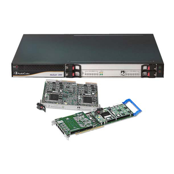
Engineering Task Force (IETF) RFC 3261 (refer to http://www.ietf.org). Mediant 2000 Overview The Mediant 2000 system is a SIP-based Voice-over-IP (VoIP) media gateway. Mediant 2000 enables voice, fax, and data traffic to be sent over the same IP network. The Mediant 2000 provides excellent voice quality and optimized packet voice streaming over IP networks. -
Page 16: Figure 1-1: Mediant 2000 Typical Application
Mediant 2000 & TP-1610 & TP-260/UNI The gateway can also route calls over the network using SIP signaling protocol, enabling the deployment of Voice over Packet solutions in environments where access is enabled to PSTN subscribers by using a trunking gateway. This provides the ability to transmit voice and telephony signals between a packet network and a TDM network. -
Page 17: Tp-1610 Overview
VoIP gateway applications providing excellent voice quality and optimized packet voice streaming over IP networks. The TP-1610 implements the award-winning, field-proven VoIPerfect™ voice compression technology typically used in other AudioCodes products. Employing SIP as a control protocol, the TP-1610 enables vendors and System Integrators (SIs) short time-to-market and reliable cost-effective deployment of next- generation networks. -
Page 18: Overview
TP-260 enables System Integrators short time-to-market and reliable cost-effective deployment of next-generation networks. The TP-260 utilizes the TPM-1100 PMC module, which is based on the VolPerfect™ architecture, AudioCodes' underlying core media gateway technology. The TP-260 matches the density requirements for small to medium locations, while meeting NSP’s demands for scalability. -
Page 19: Physical Description
SIP User's Manual 2. Physical Description Physical Description This section provides a physical description on the hardware (i.e., ports, buttons, and LEDs) of the front and rear panels of following products: Mediant 2000 (refer to 'Mediant 2000 Physical Description' on page 19) TP-1610 (refer to 'TP-1610 Physical Description' on page 21) TP-260 (refer to 'TP-260 Physical Description' on page 25) Mediant 2000 Physical Description... -
Page 20: Mediant 2000 Chassis
Mediant 2000 & TP-1610 & TP-260/UNI Table 2-1: Mediant 2000 Front View Component Descriptions Item # Label Component Description Dual AC Power LED FAULT cPCI blade locking screws cPCI latches TP-1610 cPCI blade, 16-trunk configuration Status LED Indicators E1/T1 Trunk Status LED Indicators T1/E1 STATUS Ethernet LED Indicators Reset button... -
Page 21: Optional Cpu Blade
SIP User's Manual 2. Physical Description 2.1.3 Optional CPU Blade The Mediant 2000 provides an optional second cPCI slot that can be optionally used for the customer’s CPU blade. This CPU blade can be used for general applications such as a gatekeeper, softswitch, and application server. -
Page 22: Tp-1610 Front Panel Leds
Mediant 2000 & TP-1610 & TP-260/UNI Table 2-3: Front and Upper View of the TP-1610 cPCI Blade Component Descriptions Item # Label Component Description Status LEDs Ethernet LEDs Reset button cPCI LEDs cPCI Latch T1/E1 Trunk Status LEDs (for each of the 1 - 8 trunks) T1 / E1 STATUS T1/E1 Trunk Status LEDs (for each of the 9 - 16 trunks) T1 / E1 STATUS... -
Page 23: Tp-1610 Rear Transition Module
SIP User's Manual 2. Physical Description Table 2-6: Ethernet LEDs Description Label Color Status Description Link all OK LINK Green Transmit / receive activity Yellow Table 2-7: cPCI LEDs Description Label Color Status Description Power is supplied to the blade Green The cPCI blade can be removed The cPCI blade was inserted successfully (for detailed... -
Page 24: Figure 2-3: Rtm-1610 Rear Panel With Two 50-Pin Connectors For 16 Trunks
Mediant 2000 & TP-1610 & TP-260/UNI 16 E1/T1 spans: two 50-pin female Telco connectors (DDK 57AE-40500-21D), as shown in the figure below: Figure 2-3: RTM-1610 Rear Panel with two 50-pin Connectors for 16 Trunks Table 2-8: Rear Panel with two 50-pin Connectors for 16 Trunks Component Descriptions Item # Label Component Description... -
Page 25: Physical Description
SIP User's Manual 2. Physical Description TP-260 Physical Description The TP-260 blade is a complete plug-and-play device. The PC’s boot-up sequence determines its I/O addresses and interrupts. Figure 2-5: TP-260 Board Description Table 2-10: TP-260 Component Description Item # Component Description Ethernet LEDs (refer to 'TP-260 LEDs' on page 26) Reset button Internally-located base blade LEDs (refer to 'TP-260 LEDs' on page 26) -
Page 26: Leds
Mediant 2000 & TP-1610 & TP-260/UNI 2.3.1 TP-260 LEDs The TP-260 LED descriptions are provided in the tables below. Table 2-11: Ethernet LEDs Description Label Color Status Description Receiving data Yellow Ethernet connection is ON (Link) Link Green Table 2-12: E1/T/J1 LEDs on the Front Panel (Bracket) Description Label Color Status... -
Page 27: Ethernet And E1/T1 Ports
SIP User's Manual 2. Physical Description 2.3.2 TP-260 Ethernet and E1/T1 Ports The Ethernet RJ-45 port connector pinouts are shown in the figure below: Figure 2-6: RJ-45 Connector Pinouts The E1/T1 RJ-48c port connector pinouts are shown in the figure below: Figure 2-7: RJ-48c Connector Pinouts Version 5.2 September 2007... - Page 28 Mediant 2000 & TP-1610 & TP-260/UNI Reader's Notes SIP User's Manual Document #: LTRT-68806...
-
Page 29: Installation
Remove the Mediant 2000 from the carton. Check that there is no equipment damage. Check, retain and process any documents. Notify AudioCodes or your local supplier of any damage or discrepancies. Retain any diskettes or CDs. Version 5.2 September 2007... -
Page 30: Package Contents
Mediant 2000 & TP-1610 & TP-260/UNI 3.1.2 Package Contents Ensure that in addition to the Mediant 2000, the package contains: For the dual AC power supply version two AC power cables are supplied; for the single AC power supply version one AC power cable is supplied. For the DC power supply version, one connectorized DC power cable (crimp connection type) and one DC adaptor (screw connection type) connected to the rear panel of the Mediant 2000 are supplied;... -
Page 31: Mounting Mediant 2000 On A Desktop
SIP User's Manual 3. Installation 3.1.3.1 Mounting Mediant 2000 on a Desktop The Mediant 2000 can be mounted on a desktop by attaching the four anti-slide bumpers (supplied) to the underside of the Mediant 2000. Once you have attached these bumpers, simply place it on the desktop in the position you require. -
Page 32: Figure 3-2: Front View With 19-Inch Rack-Mount Brackets
Use standard 19-inch rack bolts (not provided) to fasten the device to the frame of the rack. AudioCodes recommends using two additional rear mounting brackets (not supplied) for added support. If you are assembling the rear brackets by yourself, please note the following: Notes: •... -
Page 33: Cabling The Mediant 2000
SIP User's Manual 3. Installation 3.1.4 Cabling the Mediant 2000 This section describes Mediant 2000 cabling, which includes the following: Connecting the E1/T1 trunk interfaces (refer to 'Connecting the E1/T1 Trunk Interfaces' on page 35) Connecting the Ethernet interface (refer to 'Connecting the Ethernet Interface' on page Connecting the RS-232 port to a PC (refer to 'Connecting the RS-232 Port to a PC' on page 37) Connecting the power supply (refer to 'Connecting to the Power Supply' on page 38) -
Page 34: Figure 3-4: Rear-Panel Cabling (8 Trunks, Dc Power)
Mediant 2000 & TP-1610 & TP-260/UNI The figure below shows an example of the rear-panel cabling for Mediant 2000 providing eight trunks and supporting DC power. Figure 3-4: Rear-Panel Cabling (8 Trunks, DC Power) Table 3-2: Mediant 2000 Rear Panel Cabling (8 Trunks, DC Power) Component Descriptions Item # Label Component Description... -
Page 35: Grounding The Mediant 2000
SIP User's Manual 3. Installation 3.1.4.1 Grounding the Mediant 2000 Permanently connect the device to a suitable earth with the protective earthing screw on the rear connector panel, using 14-16 AWG wire. Electrical Earthing The unit must be permanently connected to earth via the screw provided at the back on the unit. -
Page 36: Connecting The Ethernet Interface
Mediant 2000 & TP-1610 & TP-260/UNI Table 3-3: E1/T1 Connections on each 50-pin Telco Connector E1/T1 Trunk Number Tx Pins (Tip/Ring) Rx Pins (Tip/Ring) 1 to 8 9 to 16 35/10 34/9 37/12 36/11 39/14 38/13 41/16 40/15 To connect E1/T1 trunks using RJ-48c connectors (1-, 2-, 4-, 8- trunk device) take these 2 steps: Connect the E1/T1 trunk cables to the ports labeled Trunks 1 to 8 (in the case of the 8-trunk device) on the Mediant 2000 RTM. -
Page 37: Connecting The Rs-232 Port To A Pc
SIP User's Manual 3. Installation The Ethernet connectors are wired according to the figure below. Figure 3-7: RJ-45 Connector Pinouts 3.1.4.4 Connecting the RS-232 Port to a PC Follow the procedure below to connect the Mediant 2000 serial (RS-232) interface to a PC. The RS-232 port is available only on the 1, 2 and 4-span Mediant 2000 Note: configuration. -
Page 38: Connecting The Power Supply
Mediant 2000 & TP-1610 & TP-260/UNI 3.1.4.5 Connecting the Power Supply The Mediant 2000 connection to the power supply depends on the supported hardware configuration: Single or dual AC power (refer to 'Connecting the AC Power Supply' on page 38) DC power (refer to 'Connecting the DC Power Supply' on page 38) 3.1.4.5.1 Connecting the AC Power Supply The Mediant 2000 can support up to two AC power interfaces (single or dual). -
Page 39: Figure 3-9: Dc Power Terminal Block Screw Connector
SIP User's Manual 3. Installation To connect Mediant 2000 using a DC terminal block screw connector, take these 3 steps: Create a DC cable by inserting two 14-16 AWG insulated wires into the supplied adaptor (refer to the figure below) and fasten the two screws, each one located directly above each wire. -
Page 40: Installing The Tp-1610
Remove the TP-1610 blade from the carton. Check that there is no equipment damage. Check, retain, and process any documents. Notify AudioCodes or your local supplier of any damage or discrepancies. Retain any diskettes or CDs. SIP User's Manual Document #: LTRT-68806... -
Page 41: Package Contents
SIP User's Manual 3. Installation 3.2.2 Package Contents Ensure that in addition to the TP-1610, the package contains: An RTM blade (optional) CD (software and documentation) This User’s Manual Release Notes 3.2.3 Installing the TP-1610 The TP-1610 cPCI blade is hot-swappable and can therefore be removed from a slot (and inserted into a slot) while the chassis is under power. -
Page 42: Removing Blades
Mediant 2000 & TP-1610 & TP-260/UNI 3.2.3.2 Removing Blades Follow the procedures below for removing the TP-1610 and its associated RTM blade. To remove the TP-1610 blade from the chassis, take these 3 steps: Unfasten the screws on the plate of the blade. Press the red ejector buttons on the two black ejector/injector latches on both ends and wait for the hot-swap blue LED to light, indicating that the blade can be removed. -
Page 43: Installing The Tp-260
Remove the TP-260 board from the carton. Check that there is no equipment damage. Check, retain and process any documents. Notify AudioCodes or your local supplier of any damage or discrepancies. Retain any diskettes or CDs. Version 5.2 September 2007... -
Page 44: Package Contents
Mediant 2000 & TP-1610 & TP-260/UNI 3.3.2 Package Contents Ensure that in addition to the TP-260, the package contains: Four E1/T1 cable splitters (relevant for the 8 span version only) CD (software and documentation) This User’s Manual Release Notes 3.3.3 Installing the TP-260 The TP-260 is a Peripheral Component Interconnect-based (PCI) blade designed for hosts such as PCs. -
Page 45: Connecting The E1/T1 Trunk Interfaces
Figure 3-11: RJ-48c Connector Pinouts The TP-260 E1/T1 cable splitter is part of the 8-span TP-260 product and is Note: PSTN certified. When using a non-AudioCodes E1/T1 cable splitter, AudioCodes cannot guarantee compliance with PSTN homologations. Figure 3-12: E1/T1 Cable Splitter Version 5.2... -
Page 46: Connecting The Ethernet Interface
Mediant 2000 & TP-1610 & TP-260/UNI 3.3.4.2 Connecting the Ethernet Interface Connect the TP-260 Ethernet connection, located on the front panel, directly to the network using a standard RJ-45 Ethernet cable. The Ethernet connector is wired according to the connector pinouts shown below: Figure 3-13: RJ-45 Connector Pinouts Note that when assigning an IP address to the TP-260 using HTTP (in 'Assigning an IP Address Using HTTP' on page 50), you may be required to disconnect this cable and re-... -
Page 47: Getting Started
'ini File Configuration' on page 267. An SNMP browser software (refer to the SIP Series Reference Manual). AudioCodes’ Element Management System (refer to AudioCodes’ EMS User’s Manual or EMS Product Description). To upgrade the gateway (i.e., load new software or configuration files), use the gateway's... -
Page 48: Startup Process
Mediant 2000 & TP-1610 & TP-260/UNI Startup Process The startup process (illustrated in the following figure) begins when the gateway is reset (physically, using the Embedded Web Server, or using SNMP) and ends when the operational software is running. In the startup process, the network parameters, and software and configuration files are obtained. -
Page 49: Figure 4-1: Startup Process
SIP User's Manual 4. Getting Started Figure 4-1: Startup Process Version 5.2 September 2007... -
Page 50: Assigning An Ip Address
Mediant 2000 & TP-1610 & TP-260/UNI Assigning an IP Address To assign the gateway an IP address, use one of the following methods: HTTP using a Web browser (refer to 'Assigning an IP Address Using HTTP' on page 50). BootP (refer to 'Assigning an IP Address Using BootP' on page 51). Embedded Command Line Interface (CLI) accessed via RS-232 (if supported) or Telnet (refer to 'Assigning an IP Address Using the CLI' on page 51). -
Page 51: Assigning An Ip Address Using Bootp
Assigning an IP Address Using BootP The procedure below describes how to assign the gateway an IP address using the supplied BootP application. For a detailed description on using AudioCodes' BootP application, refer to the SIP Series Reference Manual. BootP procedure can also be performed using any standard compatible Note: BootP server. -
Page 52: Accessing The Cli
Mediant 2000 & TP-1610 & TP-260/UNI 4.3.3.1 Accessing the CLI The procedure below describes how to access the CLI using either Telnet or RS-232 interface (if supported). To access the CLI using the embedded Telnet server, take these 3 steps: Enable the embedded Telnet server, by performing the following: Access the gateway's Embedded Web Server (refer to 'Accessing the Embedded Web Server' on page 60). - Page 53 SIP User's Manual 4. Getting Started 4.3.3.2 Assigning an IP Address Once you have accessed the CLI, follow the procedure below for assigning a new IP address. To assign an IP address via the CLI, take these 4 steps: At the prompt, type conf, and then press <Enter>; the configuration folder is accessed.
-
Page 54: Configuring Basic Parameters
Mediant 2000 & TP-1610 & TP-260/UNI Configuring Basic Parameters To configure the gateway's basic parameters, use the Embedded Web Server’s ‘Quick Setup’ screen (shown in the figure below). For information on accessing the Embedded Web Server, refer to 'Accessing the Embedded Web Server' on page 60. Figure 4-2: Quick Setup Screen To configure basic SIP parameters, take these 11 steps: Access the ‘Quick Setup’... - Page 55 SIP User's Manual 4. Getting Started Enter the Proxy name in the field ‘Proxy Name’. If Proxy name is used, it replaces the Proxy IP address in all SIP messages. This means that messages are still sent to the physical Proxy IP address, but the SIP URI contains the Proxy name instead. Configure ‘Enable Registration’...
- Page 56 Mediant 2000 & TP-1610 & TP-260/UNI Reader's Notes SIP User's Manual Document #: LTRT-68806...
-
Page 57: Web-Based Management
SIP User's Manual 5. Web-based Management Web-based Management The gateway's Embedded Web Server is used for remote configuration of the gateway including loading of configuration files, as well as for online monitoring of the gateway. In addition, you can also remotely reset the gateway. The Embedded Web Server can be accessed from a standard Web browser such as Microsoft™... -
Page 58: User Accounts
Mediant 2000 & TP-1610 & TP-260/UNI 5.2.1 User Accounts Up to five simultaneous users can be handled on gateway authentication via the Embedded Web Server. To prevent unauthorized access to the Embedded Web Server, two user accounts are available: primary and secondary. Each account is composed of three attributes: username, password, and access level. -
Page 59: Limiting The Embedded Web Server To Read-Only Mode
SIP User's Manual 5. Web-based Management The first time a Web browser request is made, users are requested to provide their account's username and password to obtain access. If the Embedded Web Server is left idle for more than five minutes, the session expires and the user is required to re-enter username and password. -
Page 60: Accessing The Embedded Web Server
Mediant 2000 & TP-1610 & TP-260/UNI Accessing the Embedded Web Server You can access the gateway's Embedded Web Server by following the procedure below. To access the Embedded Web Server, take these 4 steps: Open a standard Web-browsing application (for a list of supported Web browsers, refer to 'Computer Requirements' on page 57). -
Page 61: Getting Acquainted With The Web Interface
Home icon: opens the Home page screen used mainly for monitoring the gateway (refer to 'Using the Home Page' on page 260). Corporate logo: AudioCodes' corporate logo. For information on how to remove this logo, refer to 'Customizing the Web Interface' on page 65. -
Page 62: Main Menu Bar
Mediant 2000 & TP-1610 & TP-260/UNI 5.4.1 Main Menu Bar The main menu bar of the Embedded Web Server provides the following menus: Quick Setup: Accesses the 'Quick Setup' screen for quickly configuring the gateway's basic settings.For a full list of configurable parameters, directly access the Protocol Management and Advanced Configuration menus. -
Page 63: Searching For Configuration Parameters
SIP User's Manual 5. Web-based Management 5.4.4 Searching for Configuration Parameters The Embedded Web Server provides a search engine that allows you to search any ini file parameter that is configurable by the Web server. The Search button, located near the bottom of the Main menu bar is used to perform parameter searches. -
Page 64: Figure 5-3: Searched Parameter Highlighted In Screen
Mediant 2000 & TP-1610 & TP-260/UNI In the searched result list, click the required parameter to open the screen in which the parameter appears; the searched parameter is highlighted in green in the screen for easy identification, as shown in the figure below. Figure 5-3: Searched Parameter Highlighted in Screen If the searched parameter is not located, the "No Matches Found For This Note:... -
Page 65: Customizing The Web Interface
69) Login welcome message (refer to 'Creating a Login Welcome Message' on page 70) The figure below displays an example of the default title bar (i.e., of AudioCodes) and below it, a customized one: Figure 5-4: Customized Web Interface Title Bar Figure 5-5: Customized Web Interface Title Bar 5.4.5.1... -
Page 66: Figure 5-6: Image Download Screen
Mediant 2000 & TP-1610 & TP-260/UNI 5.4.5.1.1 Replacing the Main Corporate Logo with an Image File You can replace the logo in the Web interface's title bar using either the Embedded Web Server or the ini file. To replace the default logo with your own corporate image via the Embedded Web Server, take these 7 steps: Access the gateway's Embedded Web Server (refer to 'Accessing the Embedded Web Server' on page 60). -
Page 67: Table 5-3: Customizable Logo Ini File Parameters
5.4.5.1.2 Replacing the Main Corporate Logo with a Text String The main corporate logo can be replaced with a text string. To replace AudioCodes’ default logo with a text string using the ini file, add or modify the two ini file parameters listed in the table below (according to the procedure described in n 'Modifying an ini File' on page 267). -
Page 68: Replacing The Background Image File
Mediant 2000 & TP-1610 & TP-260/UNI 5.4.5.2 Replacing the Background Image File The background image file is duplicated across the width of the screen. The number of times the image is duplicated depends on the width of the background image and screen resolution. -
Page 69: Customizing The Product Name
5.4.5.3 Customizing the Product Name To replace AudioCodes’ default product name with a text string, add or modify the two ini file parameters listed in the table below (according to the procedure described in' Modifying an ini File' on page 267). -
Page 70: Creating A Login Welcome Message
Mediant 2000 & TP-1610 & TP-260/UNI 5.4.5.4 Creating a Login Welcome Message You can create a Welcome message box (alert message) that appears (see figure below for an example) after each successful login to the gateway's Embedded Web Server. The ini file parameter table WelcomeMessage allows you to create the Welcome message. -
Page 71: Protocol Management
SIP User's Manual 5. Web-based Management Protocol Management The Protocol Management menu is used to configure the gateway's SIP parameters and tables. Throughout this section, parameters enclosed in square brackets ([...]) depict Note: the ini file parameters that correspond to the Embedded Web Server parameters. -
Page 72: General Parameters
Mediant 2000 & TP-1610 & TP-260/UNI 5.5.1.1 General Parameters The General Parameters option is used to configure general SIP parameters. To configure the general SIP protocol parameters, take these 4 steps: Open the 'General Parameters' screen (Protocol Management menu > Protocol Definition submenu >... -
Page 73: Table 5-8: General Parameters (Protocol Definition)
SIP User's Manual 5. Web-based Management Configure the parameters according to the table below. Click the Submit button to save your changes. To save the changes to flash memory, refer to 'Saving Configuration' on page 256. Table 5-8: General Parameters (Protocol Definition) Parameter Description PRACK Mode... - Page 74 Mediant 2000 & TP-1610 & TP-260/UNI Table 5-8: General Parameters (Protocol Definition) Parameter Description Channel Select Mode Port allocation algorithm for IP-to-Tel calls. You can select one of the following methods: [ChannelSelectMode] [0] By Dest Phone Number = (default) Select the gateway port according to the called number.
- Page 75 SIP User's Manual 5. Web-based Management Table 5-8: General Parameters (Protocol Definition) Parameter Description 183 Message Behavior Defines the ISDN message that is sent when 183 Session Progress message is received for IP-to-Tel calls. [SIP183Behavior] Valid options include: [0] Progress = Progress message (default). [1] Alert = Alert message.
- Page 76 Mediant 2000 & TP-1610 & TP-260/UNI Table 5-8: General Parameters (Protocol Definition) Parameter Description Fax Signaling Method Determines the SIP signaling method used to establish and convey a fax session after a fax is detected. [IsFaxUsed] [0] No Fax = No fax negotiation using SIP signaling. Fax transport method is according to the parameter FaxTransportMode (default).
- Page 77 SIP User's Manual 5. Web-based Management Table 5-8: General Parameters (Protocol Definition) Parameter Description SIP Transport Type Determines the default transport layer used for outgoing SIP calls initiated by the gateway. [SIPTransportType] Valid options include: [0] UDP (default) [1] TCP [2] TLS (SIPS) Note: It's recommended to use TLS to communicate with a SIP Proxy and not for direct gateway-gateway...
- Page 78 Mediant 2000 & TP-1610 & TP-260/UNI Table 5-8: General Parameters (Protocol Definition) Parameter Description [0] No = Doesn't use ';user=phone' string in From header Use “user=phone” in From Header (default). [IsUserPhoneInFrom] [1] Yes = ';user=phone' string is part of the From header. Use Tel URI for Asserted Identity Determines the format of the URI in the P-Asserted and P- Preferred headers.
- Page 79 SIP User's Manual 5. Web-based Management Table 5-8: General Parameters (Protocol Definition) Parameter Description Enable History-Info Header Enables usage of the History-Info header. Valid options include: [EnableHistoryInfo] [0] Disable = Disable (default) [1] Enable = Enable UAC Behavior: Initial request: The History-Info header is equal to the Request URI.
- Page 80 Mediant 2000 & TP-1610 & TP-260/UNI Table 5-8: General Parameters (Protocol Definition) Parameter Description Use Source Number as Display Name Applicable to Tel-to-IP calls. [UseSourceNumberAsDisplayName] [0] No = The Tel Source Number is used as the IP Source Number and the Tel Display Name is used as the IP Display Name (if Tel Display Name is received).
- Page 81 SIP User's Manual 5. Web-based Management Table 5-8: General Parameters (Protocol Definition) Parameter Description [0] Don't Play = Ringback tone isn't played to the IP side Play Ringback Tone to IP of the call (default). [PlayRBTone2IP] [1] Play = Ringback tone is played to the IP side of the call after SIP 183 session progress response is sent.
- Page 82 Defines the string that is used in the SIP request header 'User-Agent' and SIP response header 'Server'. If not [UserAgentDisplayInfo] configured, the default string 'AudioCodes product-name s/w- version' is used (e.g., User-Agent: Audiocodes-Sip-Gateway- Mediant 2000/v.4.80.004.008). When configured, the string 'UserAgentDisplayInfo s/w-version' is used (e.g., User-Agent: MyNewOEM/v.4.80.004.008).
- Page 83 SIP User's Manual 5. Web-based Management Table 5-8: General Parameters (Protocol Definition) Parameter Description SDP Session Owner Determines the value of the Session Owner line (“o” field) in outgoing SDP bodies. [SIPSDPSessionOwner] The valid range is a string of up to 39 characters. The default value is 'AudiocodesGW'.
- Page 84 Mediant 2000 & TP-1610 & TP-260/UNI Table 5-8: General Parameters (Protocol Definition) Parameter Description Enable Semi-Attended Transfer Determines the gateway behavior when Transfer is initiated while still in Alerting state. [EnableSemiAttendedTransfer] Valid options include: [0] Disable = Send REFER with Replaces (default). [1] Enable = Send CANCEL, and after a 487 response is received, send REFER without Replaces.
- Page 85 SIP User's Manual 5. Web-based Management Table 5-8: General Parameters (Protocol Definition) Parameter Description Retransmission Parameters SIP T1 Retransmission Timer [msec] The time interval (in msec) between the first transmission of a SIP message and the first retransmission of the same [SipT1Rtx] message.
-
Page 86: Proxy & Registration Parameters
Mediant 2000 & TP-1610 & TP-260/UNI 5.5.1.2 Proxy & Registration Parameters The Proxy & Registration option is used to configure parameters that are associated with Proxy and Registration. To configure the Proxy & Registration parameters, take these 4 steps: Open the 'Proxy & Registration' parameters screen (Protocol Management menu > Protocol Definition submenu >... -
Page 87: Table 5-9: Proxy & Registration Parameters
SIP User's Manual 5. Web-based Management Configure the Proxy and Registration parameters according to the following table. Click the Submit button to save your changes, or click the Register or Un-Register buttons to save your changes and register / unregister to a Proxy / Registrar. To save the changes to flash memory, refer to 'Saving Configuration' on page 256. - Page 88 Mediant 2000 & TP-1610 & TP-260/UNI Table 5-9: Proxy & Registration Parameters Parameter Description First Redundant Proxy IP addresses of the first redundant Proxy you are using. IP Address Enter the IP address as FQDN or in dotted decimal notation (e.g., 192.10.1.255).
- Page 89 SIP User's Manual 5. Web-based Management Table 5-9: Proxy & Registration Parameters Parameter Description Proxy Load Balancing Enables the usage of the Proxy Load Balancing mechanism. Method [0] Disable = Load Balancing is disabled (default). [ProxyLoadBalancing [1] Round Robin = Round Robin. Method] [2] Random Weights = Random Weights.
- Page 90 Mediant 2000 & TP-1610 & TP-260/UNI Table 5-9: Proxy & Registration Parameters Parameter Description Enable Proxy Keep Determines whether Keep-Alive with the Proxy is enabled or disabled. Alive [0] Disable = Disable (default)\ [EnableProxyKeepAli [1] Using OPTIONS = Enable Keep alive with Proxy using OPTIONS [2] Using REGISTER = Enable Keep alive with Proxy using REGISTER If EnableProxyKeepAlive = 1, SIP OPTIONS message is sent every ProxyKeepAliveTime.
- Page 91 SIP User's Manual 5. Web-based Management Table 5-9: Proxy & Registration Parameters Parameter Description Use Routing Table for Use the internal Tel to IP routing table to obtain the URI Host name and Host Names and (optionally) an IP profile (per call), even if Proxy server is used. Profiles [0] Disable = Don't use (default).
- Page 92 Mediant 2000 & TP-1610 & TP-260/UNI Table 5-9: Proxy & Registration Parameters Parameter Description Registrar IP Address IP address (numerical or FQDN) and optionally port number of Registrar server. [RegistrarIP] Enter the IP address in dotted format notation, for example, 201.10.8.1:<5080>.
- Page 93 SIP User's Manual 5. Web-based Management Table 5-9: Proxy & Registration Parameters Parameter Description Miscellaneous parameters Gateway Name Assigns a name to the gateway (e.g., 'gateway1.com'). Ensure that the name you choose is the one that the Proxy is configured with to identify your [SIPGatewayName] gateway.
- Page 94 Mediant 2000 & TP-1610 & TP-260/UNI Table 5-9: Proxy & Registration Parameters Parameter Description Proxy DNS Query Type Enables the use of DNS Naming Authority Pointer (NAPTR) and Service Record (SRV) queries to discover Proxy servers. [ProxyDNSQueryType Valid options include: [0] A-Record = A-Record (default) [1] SRV = SRV [2] NAPTR = NAPTR...
- Page 95 SIP User's Manual 5. Web-based Management Table 5-9: Proxy & Registration Parameters Parameter Description Number of RTX Before Number of retransmitted INVITE/REGISTER messages before call is routed Hot-Swap (hot swap) to another Proxy/Registrar. The valid range is 1 to 30. The default value is 3. [HotSwapRtx] Note: This parameter is also used for alternative routing using the Tel to IP Routing table.
-
Page 96: Coders
Mediant 2000 & TP-1610 & TP-260/UNI Table 5-9: Proxy & Registration Parameters Parameter Description Mutual Authentication Determines the gateway's mode of operation when Authentication and Key Mode Agreement (AKA) Digest Authentication is used. Valid options include: [MutualAuthentication Mode] [0] Optional = Incoming requests that don't include AKA authentication information are accepted. -
Page 97: Table 5-10: Supported Coders
A pre-defined table can be configured to provide a set of rules for automatic AMR rate change. The decision for the change is based upon packet loss rate. To obtain more information about this option, contact AudioCodes. Table 5-10: Supported Coders Coder Name... - Page 98 Mediant 2000 & TP-1610 & TP-260/UNI Table 5-10: Supported Coders Coder Name Packetization Time Rate Payload Type Silence Suppression 10, 20 (default), 30, 16 [0], 24 [1], Dynamic (0- Disable [0] G.726 40, 50, 60, 80, 100, 32 [2] 120) Enable [1] [g726] (default)
-
Page 99: Dtmf & Dialing Parameters
SIP User's Manual 5. Web-based Management 5.5.1.4 DTMF & Dialing Parameters The DTMF & Dialing option is used to configure parameters associated with dual-tone multi-frequency (DTMF) and dialing. To configure the DTMF and dialing parameters, take these 4 steps: Open the 'DTMF & Dialing' screen (Protocol Management menu > Protocol Definition submenu >... -
Page 100: Table 5-11: Dtmf And Dialing Parameters
Mediant 2000 & TP-1610 & TP-260/UNI Table 5-11: DTMF and Dialing Parameters Parameter Description Max Digits in Phone Num Defines the maximum number of collected destination number digits that can be received from the Tel side when Tel-to-IP overlap dialing is [MaxDigits] performed (ISDN uses overlap dialing). - Page 101 SIP User's Manual 5. Web-based Management Table 5-11: DTMF and Dialing Parameters Parameter Description to 5 Tx DTMF Option Determines a single or several preferred transmit DTMF negotiation methods. [TxDTMFOption] Valid options include: [0] Not Supported = No negotiation, DTMF digits are sent according to the parameters DTMFTransportType and RFC2833PayloadType (default).
-
Page 102: Configuring The Advanced Parameters
Mediant 2000 & TP-1610 & TP-260/UNI Table 5-11: DTMF and Dialing Parameters Parameter Description Digit Mapping Rules Digit map pattern (used to reduce the dialing period when Overlap dialing is used). If the digit string (dialed number) has matched one of the patterns [DigitMapping] in the digit map, the gateway stops collecting digits and starts to establish a call with the collected number. -
Page 103: General Parameters
SIP User's Manual 5. Web-based Management 5.5.2.1 General Parameters The General Parameters option is used to configure general control protocol parameters. To configure the advanced general protocol parameters, take these 4 steps: Open the 'General Parameters' screen (Protocol Management menu > Advanced Parameters submenu >... -
Page 104: Table 5-12: General Parameters (Advanced Parameters)
Mediant 2000 & TP-1610 & TP-260/UNI Table 5-12: General Parameters (Advanced Parameters) Parameter Description [0] Disable = gateway accepts all SIP calls (default). IP Security [SecureCallsFromIP] [1] Enable = gateway accepts SIP calls only from IP addresses defined in the Tel to IP Routing table (refer to 'Tel to IP Routing Table' on page 122). - Page 105 SIP User's Manual 5. Web-based Management Table 5-12: General Parameters (Advanced Parameters) Parameter Description RTP Only Mode Enables the gateway to start sending and/or receiving RTP packets to and from remote endpoints without the need to establish a Control [RTPOnlyMode] session.
- Page 106 Mediant 2000 & TP-1610 & TP-260/UNI Table 5-12: General Parameters (Advanced Parameters) Parameter Description Broken Connection The amount of time (in 100 msec units) an RTP packet isn't received, Timeout after which a call is disconnected. The valid range is 1 to 1000. The default value is 100 (i.e., 10 seconds). [BrokenConnectionEvent Timeout] Notes:...
- Page 107 SIP User's Manual 5. Web-based Management Table 5-12: General Parameters (Advanced Parameters) Parameter Description CDR Report Level Determines whether or not CDRs are sent to the Syslog server, and if enabled, at which events they are sent. [CDRReportLevel] Valid options include: [0] None = Call Detail Record (CDR) is not used [1] End Call = CDR is sent to the Syslog server at the end of each call.
- Page 108 Mediant 2000 & TP-1610 & TP-260/UNI Table 5-12: General Parameters (Advanced Parameters) Parameter Description [0] Disable = x-channel header is not used (default). Enable X-Channel Header [XChannelHeader] [1] Enable = x-channel header is generated with trunk/B-channel information. The header provides information on the E1/T1 physical trunk/B-channel on which the call is received or placed.
-
Page 109: Supplementary Services
SIP User's Manual 5. Web-based Management Table 5-12: General Parameters (Advanced Parameters) Parameter Description Max Call Duration (min) Defines the maximum call duration in minutes. If this time expires, both sides of the call are released (IP and Tel). [MaxCallDuration] The valid range is 0 to 35791. -
Page 110: Table 5-13: Supplementary Services Parameters
Mediant 2000 & TP-1610 & TP-260/UNI Click the Submit button to save your changes, or click the Subscribe to MWI or Unsubscribe to MWI buttons to save your changes and to subscribe / unsubscribe to the MWI server. To save the changes to flash memory, refer to 'Saving Configuration' on page 256. Table 5-13: Supplementary Services Parameters Parameter Description... -
Page 111: Stand-Alone Survivability
SIP User's Manual 5. Web-based Management Table 5-13: Supplementary Services Parameters Parameter Description Hook-Flash Code Determines the digit pattern used by the PBX to indicate a 'Hook-Flash' event. When this pattern is detected from the Tel side, the gateway [HookFlashCode] responds as if a Hook-Flash event occurs and sends an INFO message indicating 'Hook Flash'. -
Page 112: Figure 5-12: Stand-Alone Survivability Screen
Mediant 2000 & TP-1610 & TP-260/UNI To configure the Stand-Alone Survivability parameters, take these 4 steps: Open the 'Supplementary Services' screen (Protocol Management menu > Advanced Parameters submenu > Stand-Alone Survivability option). Figure 5-12: Stand-Alone Survivability Screen Configure the parameters according to the table below. Click the Submit button to apply your changes. -
Page 113: Configuring The Number Manipulation Tables
SIP User's Manual 5. Web-based Management 5.5.3 Configuring the Number Manipulation Tables The VoIP gateway provides four Number Manipulation tables for incoming and outgoing calls. These tables are used to modify the destination and source telephone numbers so that the calls can be routed correctly. The Manipulation Tables include: Destination Phone Number Manipulation Table for IP-to-Tel calls Destination Phone Number Manipulation Table for Tel-to-IP calls... -
Page 114: Figure 5-13: Source Phone Number Manipulation Table For Tel-To-Ip Calls
Mediant 2000 & TP-1610 & TP-260/UNI To configure the Number Manipulation tables, take these 5 steps: Open the required 'Number Manipulation' screen (Protocol Management menu > Manipulation Tables submenu); the relevant Manipulation table screen is displayed (e.g., 'Source Phone Number Manipulation Table for Tel IP Calls' screen). Figure 5-13: Source Phone Number Manipulation Table for Tel-to-IP Calls The figure above exemplifies the use of the manipulation rules in the 'Source Phone Number Manipulation Table for Tel IP Calls':... -
Page 115: Table 5-15: Number Manipulation Parameters
SIP User's Manual 5. Web-based Management Table 5-15: Number Manipulation Parameters Parameter Description Destination (called) telephone number prefix. An asterisk (*) represents Destination Prefix any number. Source (caller) telephone number prefix. An asterisk (*) represents any Source Prefix number. Source IP address of the call (obtained from the Contact header in the Source IP (Applicable only to the INVITE message). -
Page 116: Dialing Plan Notation
Mediant 2000 & TP-1610 & TP-260/UNI Table 5-15: Number Manipulation Parameters Parameter Description Select the Numbering Plan Indicator (NPI) assigned to this entry. [0] Unknown (default) [9] Private [1] E.164 Public [-1] Not Configured = value received from PSTN/IP is used For a detailed list of the available NPI/TON values, refer to 'Numbering Plans and Type of Number' on page Select the Type of Number (TON) assigned to this entry. -
Page 117: Numbering Plans And Type Of Number
SIP User's Manual 5. Web-based Management The gateway matches the rules starting at the top of the table (i.e., top rules take precedence over lower rules). For this reason, enter more specific rules above more generic rules. For example, if you enter 551 in entry 1 and 55 in entry 2, the gateway applies rule 1 to numbers that starts with 551 and applies rule 2 to numbers that start with 550, 552, 553, 554, 555, 556, 557, 558 and 559. -
Page 118: Mapping Npi/Ton To Phone-Context
Mediant 2000 & TP-1610 & TP-260/UNI 5.5.3.3 Mapping NPI/TON to Phone-Context The Phone-Context Table option is used to configure the mapping of NPI and TON to the Phone-Context SIP parameter. When a call is received from the ISDN, the NPI and TON are compared against the table and the Phone-Context value is used in the outgoing SIP INVITE message. -
Page 119: Table 5-18: Phone-Context Parameters
SIP User's Manual 5. Web-based Management Notes: • Several rows with the same NPI-TON or Phone-Context are allowed. In such a scenario, a Tel-to-IP call uses the first match. • Phone-Context '+' is a unique case as it doesn't appear in the Request- URI as a Phone-Context parameter. -
Page 120: Configuring The Routing Tables
Mediant 2000 & TP-1610 & TP-260/UNI 5.5.4 Configuring the Routing Tables The Routing Tables submenu is used to configure the gateway's IP-to-Tel and Tel-to-IP routing tables and their associated parameters: General Parameters (refer to 'General Parameters' on page 120) Tel to IP Routing Table (refer to 'Tel to IP Routing Table' on page 122) IP to Trunk Group Routing (refer to 'IP to Trunk Group Routing' on page 126) Internal DNS Table (refer to 'Internal DNS Table' on page 128) Internal SRV Table (refer to 'Internal SRV Table' on page 129) -
Page 121: Table 5-19: General Parameters (Routing Tables)
SIP User's Manual 5. Web-based Management Table 5-19: General Parameters (Routing Tables) Parameter Description [0] No = Don't add trunk group ID as prefix (default). Add Trunk Group ID as Prefix [1] Yes = Add trunk group ID as prefix to called number. [AddTrunkGroupAsPref If enabled, then the gateway's trunk group ID is added as a prefix to the destination phone number for Tel-to-IP calls. -
Page 122: Tel To Ip Routing Table
Mediant 2000 & TP-1610 & TP-260/UNI Table 5-19: General Parameters (Routing Tables) Parameter Description Enable Alt Routing Tel to Determines the operation modes for the Alternative Routing mechanism. [0] Disable = Disable the Alternative Routing feature (default). [AltRoutingTel2IPEnabl [1] Enable = Enable the Alternative Routing feature. [2] Status Only = The Alternative Routing feature is disabled and a read-only information on the quality of service of the destination IP addresses is provided. - Page 123 SIP User's Manual 5. Web-based Management When using a Proxy server, you do not need to configure the Tel to IP Routing Table. However, if you want to use fallback routing when communication with Proxy servers is lost, or to use the 'Filter Calls to IP' and 'IP Security' features, or to obtain different SIP URI host names (per called number) or to assign IP profiles, you need to configure the IP Routing Table.
-
Page 124: Figure 5-16: Tel To Ip Routing Table Screen
Mediant 2000 & TP-1610 & TP-260/UNI If the alternative routing destination is the gateway itself, the call can be Note: configured to be routed back to PSTN. This feature is referred to as 'PSTN Fallback', meaning that if sufficient voice quality is not available over the IP network, the call is routed through the legacy telephony system (PSTN). -
Page 125: Table 5-20: Tel To Ip Routing Table
SIP User's Manual 5. Web-based Management Table 5-20: Tel to IP Routing Table Parameter Description Tel to IP Routing Mode Defines the order between routing incoming calls to IP, using routing table, and manipulation of destination number. [RouteModeTel2IP] [0] Route calls before manipulation = Tel-to-IP calls are routed before the number manipulation rules are applied (default). -
Page 126: Ip To Trunk Group Routing
Mediant 2000 & TP-1610 & TP-260/UNI 5.5.4.3 IP to Trunk Group Routing The IP to Trunk Group Routing Table is used to route incoming IP calls to groups of E1/T1 B-channelscalled trunk groups. Calls are assigned to trunk groups according to any combination of the following three options (or using each independently): Destination phone prefix Source phone prefix... -
Page 127: Figure 5-17: Ip To Trunk Group Routing Table Screen
SIP User's Manual 5. Web-based Management To configure the IP to Trunk Group Routing table, take these 6 steps: Open the 'IP to Trunk Group Routing' screen (Protocol Management menu > Routing Tables submenu > IP to Trunk Group Routing option). Figure 5-17: IP to Trunk Group Routing Table Screen From the 'IP to Tel Routing Mode' field, select the IP to Tel routing mode (refer to the table below). -
Page 128: Internal Dns Table
Mediant 2000 & TP-1610 & TP-260/UNI Table 5-21: IP to Trunk Group Routing Table Parameter Description Represents the source IP address of an IP-to-Tel call (obtained from the Source IP Address Contact header in the INVITE message). Note: The source IP address can include the 'x' wildcard to represent single digits. -
Page 129: Internal Srv Table
SIP User's Manual 5. Web-based Management To configure the internal DNS table, take these 7 steps: Open the 'Internal DNS Table' screen (Protocol Management menu > Routing Tables submenu > Internal DNS Table option). Figure 5-18: Internal DNS Table Screen In the 'Domain Name' field, enter the host name to be translated. -
Page 130: Reasons For Alternative Routing
Mediant 2000 & TP-1610 & TP-260/UNI If the Internal SRV table is configured, the gateway first tries to resolve a Note: domain name using this table. If the domain name isn't found, the gateway performs an SRV resolution using an external DNS server. To configure the Internal SRV table, take these 9 steps: Open the 'Internal SRV Table' screen (Protocol Management menu >... -
Page 131: Figure 5-20: Reasons For Alternative Routing Screen
SIP User's Manual 5. Web-based Management You can use the 'Reasons for Alternative Routing' screen in the following example scenarios: For Tel-to-IP calls: when there is no response to an INVITE message (after INVITE retransmissions), and the gateway then issues an internal 408 'No Response' implicit release reason. -
Page 132: Release Cause Mapping
Mediant 2000 & TP-1610 & TP-260/UNI 5.5.4.7 Release Cause Mapping The 'Release Cause Mapping' screen consists of two tables that allow the gateway to map up to 12 different SIP Responses to Q.850 Release Causes and vice versa, thereby overriding the hard-coded mapping mechanism (described in 'Release Cause Mapping' on page 132). -
Page 133: Coder Group Settings
SIP User's Manual 5. Web-based Management Use the Profile Definitions submenu to configure profiles: Coder Group Settings (refer to 'Coder Group Settings' on page 133) Tel Profile Settings (refer to 'Tel Profile Settings' on page 134) IP Profile Settings (refer to 'IP Profile Settings' on page 136) The default values of the parameters in the Tel and IP Profiles are identical to Note: the Embedded Web Server/ini file parameter values. -
Page 134: Tel Profile Settings
Mediant 2000 & TP-1610 & TP-260/UNI From the 'Coder Group ID' drop-down list, select a coder group ID that you want to add (up to four coder groups can be configured). From the 'Coder Name' drop-down list, select the first coder for the coder group. For a full list of available coders and their corresponding attributes, refer to 'Coders' on page From the 'Packetization Time' drop-down list, select the packetization time (in msec) for the coder. - Page 135 SIP User's Manual 5. Web-based Management To configure Tel Profiles, take these 9 steps: Open the 'Tel Profile Settings' screen (Protocol Management menu > Profile Definitions submenu > Tel Profile Settings option). From the 'Profile ID' drop-down list, select the Tel Profile identification number you want to edit (up to four Tel Profiles can be configured).
-
Page 136: Ip Profile Settings
Mediant 2000 & TP-1610 & TP-260/UNI Configure the Profile's parameters according to your requirements. For detailed information on each parameter, refer to the description of the screen in which it is configured as an individual parameter. From the 'Coder Group' drop-down list, select the coder group to which you want to assign the Profile. -
Page 137: Figure 5-23: Ip Profile Settings Screen
SIP User's Manual 5. Web-based Management To configure the IP Profile settings, take these 9 steps: Open the 'IP Profile Settings' screen (Protocol Management menu > Profile Definitions submenu > IP Profile Settings option. Figure 5-23: IP Profile Settings Screen From the 'Profile ID' drop-down list, select the IP Profile you want to edit (up to four IP Profiles can be configured). -
Page 138: Configuring The Trunk Group Table
Mediant 2000 & TP-1610 & TP-260/UNI From the 'Profile Preference' drop-down list, select the preference (1-20) of the current Profile. The preference option is used to determine the priority of the Profile. Where '20' is the highest preference value. If both IP and Tel profiles apply to the same call, the coders and other common parameters (noted by an asterisk in the description of the parameter IPProfile) of the preferred Profile are applied to that call. -
Page 139: Table 5-22: Trunk Group Table
SIP User's Manual 5. Web-based Management Table 5-22: Trunk Group Table Parameter Description Starting physical trunk number (0 - 7). From Trunk Ending physical trunk number (0 - 7). To Trunk Note: Applicable only to digital modules. Represents the trunk's B-channels. Channels To enable the trunk's channels, enter the channels number in this field. -
Page 140: Configuring The Trunk Group Settings
Mediant 2000 & TP-1610 & TP-260/UNI 5.5.7 Configuring the Trunk Group Settings The Trunk Group Settings option is used to determine the method in which new calls are assigned to channels within each trunk group. If such a rule doesn't exist (for a specific Trunk group), the global rule, defined by the 'Channel Select Mode' parameter (Protocol Definition >... -
Page 141: Table 5-23: Hunt Group Settings Parameters
SIP User's Manual 5. Web-based Management Table 5-23: Hunt Group Settings Parameters Mode Description Trunk Group ID to which you want to determine the method in which new calls Trunk Group ID are assigned to channels within the trunk group. Method in which new calls are assigned to channels within the Trunk Group Channel Select entered in the 'Trunk Group ID' field:... -
Page 142: Configuring The Digital Gateway Parameters
Mediant 2000 & TP-1610 & TP-260/UNI 5.5.8 Configuring the Digital Gateway Parameters The 'Digital Gateway' screen is used to configure miscellaneous digital parameters. To configure the digital gateway parameters, take these 4 steps: Open the 'Digital gateway Parameters' screen (Protocol Management menu > Digital Gateway Parameters). -
Page 143: Table 5-24: Digital Gateway Parameters
SIP User's Manual 5. Web-based Management Table 5-24: Digital Gateway Parameters Parameter Description B-channel Negotiation Determines the ISDN B-Channel negotiation mode. [BchannelNegotiation] [0] Preferred = Preferred [1] Exclusive = Exclusive (default) [2] Any = Any Notes: Applicable to ISDN protocols. •... - Page 144 Mediant 2000 & TP-1610 & TP-260/UNI Table 5-24: Digital Gateway Parameters Parameter Description Send Screening Indicator to Overwrites the screening indicator of the calling number for ISDN IP Tel (ISDN) calls. [ScreeningInd2ISDN] [-1] Not Configured = Not configured (interworking from IP to ISDN) (default).
- Page 145 SIP User's Manual 5. Web-based Management Table 5-24: Digital Gateway Parameters Parameter Description Enable ISDN Tunneling Tel to IP Valid options include: [EnableISDNTunnelingTel2IP] [0] Disable = Disable (default). [1] Using Header = Enable ISDN Tunneling from ISDN PRI to SIP using a proprietary SIP header. [2] Using Body = Enable ISDN Tunneling from ISDN PRI to SIP using a dedicated message body.
- Page 146 Mediant 2000 & TP-1610 & TP-260/UNI Table 5-24: Digital Gateway Parameters Parameter Description [0] Alert = Enable ISDN Transfer if outgoing call is in Alert state ISDN Transfer On Connect (default). [SendISDNTransferOnConnect] [1] Connect = Enable ISDN Transfer only if outgoing call is in Connect state.
-
Page 147: Configuring The Advanced Applications
SIP User's Manual 5. Web-based Management Table 5-24: Digital Gateway Parameters Parameter Description MLPP Default Namespace Determines the Namespace used for MLPP calls received from the ISDN side and destined for the Application Server. [MLPPDefaultNamespace] The Namespace value is not present in the Precedence IE of the PRI SETUP message. -
Page 148: Figure 5-27: Radius Parameters Screen
Mediant 2000 & TP-1610 & TP-260/UNI To configure the RADIUS parameters, take these 4 steps: Open the ‘RADIUS Parameters' screen (Protocol Management menu > Advanced Applications submenu > RADIUS Parameters). Figure 5-27: RADIUS Parameters Screen Configure the RADIUS accounting parameters according to the table below. Click the Submit button to save your changes. -
Page 149: Configuring The Voice Mail (Vm) Parameters
SIP User's Manual 5. Web-based Management 5.5.9.2 Configuring the Voice Mail (VM) Parameters The 'Voice Mail' screen is used to configure the Voice Mail (VM) parameters. The VM application applies only to FXO/CAS gateways. For detailed information on VM, refer to the CPE Configuration Guide for Voice Mail User's Manual. -
Page 150: Table 5-26: Voice Mail Parameters
Mediant 2000 & TP-1610 & TP-260/UNI Table 5-26: Voice Mail Parameters Parameter Description General Voice Mail Interface Enables the VM application on the gateway and determines the communication method used between the PBX and the gateway. [VoiceMailInterface] [0] None (default) [1] DTMF [2] SMDI [3] QSIG... - Page 151 SIP User's Manual 5. Web-based Management Table 5-26: Voice Mail Parameters Parameter Description Forward on No Answer Determines the digit pattern used by the PBX to indicate 'call forward on Digit Pattern (Internal) no answer' when the original call is received from an internal extension. [DigitPatternForwardOnN The valid range is a 120-character string.
-
Page 152: Network Settings
Mediant 2000 & TP-1610 & TP-260/UNI Table 5-26: Voice Mail Parameters Parameter Description MWI Suffix Pattern Determines a digit code used by the gateway as a suffix for MWIOnCode and MWIOffCode. This suffix is added to the generated DTMF string [MWISuffixCode] after the extension number. -
Page 153: Configuring The Ip Settings
SIP User's Manual 5. Web-based Management 5.6.1 Configuring the IP Settings The 'IP Settings' screen is used for configuring various IP networking parameters. To configure the IP Settings parameters, take these 4 steps: Open the 'IP Settings' screen (Advanced Configuration menu > Network Settings > IP Settings option). -
Page 154: Table 5-27: Network Settings -- Ip Settings Parameters
Mediant 2000 & TP-1610 & TP-260/UNI Table 5-27: Network Settings -- IP Settings Parameters Parameter Description IP Networking Mode Enables / disables the Multiple IPs mechanism. [EnableMultipleIPs] [0] Single IP Network = Single IP network (default). [1] Multiple IP Network = Multiple IP networks. [1] Dual IP (Media &... - Page 155 SIP User's Manual 5. Web-based Management Table 5-27: Network Settings -- IP Settings Parameters Parameter Description Default Gateway Address N/A. Use the IP Routing table instead (refer to 'Configuring the IP Routing Table' on page 162). [LocalControlDefaultGW] Media Network Settings (available only in Multiple IPs and Dual IP modes) IP Address The gateway's source IP address in the Media network.
- Page 156 Mediant 2000 & TP-1610 & TP-260/UNI Table 5-27: Network Settings -- IP Settings Parameters Parameter Description Differential Services. For detailed information on IP QoS via Differentiated Services, refer to 'IP QoS via Differentiated Services (DiffServ)' on page 372. Network QoS Sets the DiffServ value for Network service class content.
-
Page 157: Configuring The Application Settings
SIP User's Manual 5. Web-based Management 5.6.2 Configuring the Application Settings The 'Application Settings' screen is used for configuring various application parameters (e.g., for Telnet). To configure the Application Settings parameters, take these 4 steps: Open the 'Application Settings' screen (Advanced Configuration menu > Network Settings >... -
Page 158: Table 5-28: Network Settings, Application Settings Parameters
Mediant 2000 & TP-1610 & TP-260/UNI Table 5-28: Network Settings, Application Settings Parameters Parameter Description NTP Settings For detailed information on Network Time Protocol (NTP), refer to 'Simple Network Time Protocol Support' on page 372. NTP Server IP Address IP address (in dotted format notation) of the NTP server. The default IP address is 0.0.0.0 (the internal NTP client is disabled). -
Page 159: Configuring The Nfs Settings
SIP User's Manual 5. Web-based Management Table 5-28: Network Settings, Application Settings Parameters Parameter Description STUN Settings [0] Disable = STUN protocol is disabled (default). Enable STUN [EnableSTUN] [1] Enable = STUN protocol is enabled. When enabled, the gateway functions as a STUN client and communicates with a STUN server located in the public Internet. -
Page 160: Figure 5-30: Nfs Settings Screen
Mediant 2000 & TP-1610 & TP-260/UNI To configure the NFS Settings parameters, take these 7 steps: Open the 'Application Settings' screen (Advanced Configuration menu > Network Settings > Application Settings option); the 'Application Settings' screen is displayed (refer to 'Configuring the Application Settings' on page 157). Open the 'NFS Settings' screen by clicking the NFS Table arrow sign (-->). -
Page 161: Table 5-29: Network Settings -- Nfs Settings Parameters
SIP User's Manual 5. Web-based Management To modify an existing remote NFS file system, take these 4 steps: Select the Edit radio button for the row to be modified. Change the values on the selected row according to your requirements. Click the Apply New Settings button;... -
Page 162: Configuring The Ip Routing Table
Mediant 2000 & TP-1610 & TP-260/UNI 5.6.4 Configuring the IP Routing Table The 'IP Routing Table' screen is used by the gateway to determine IP routing rules. It can be used, for example, to define static routing rules for the OAM and Control networks since a default gateway isn't supported for these networks (refer to 'Multiple IPs' on page 373). - Page 163 SIP User's Manual 5. Web-based Management Table 5-30: IP Routing Table Column Description Column Name Description [ini File Parameter Name] The address of the host / network you want to reach is determined by an AND operation that is applied on the fields 'Destination IP Address' and 'Destination Mask'. For example: To reach the network 10.8.x.x, enter 10.8.0.0 in the field 'Destination IP Address' and 255.255.0.0 in the field 'Destination Mask'.
-
Page 164: Configuring The Vlan Settings
Mediant 2000 & TP-1610 & TP-260/UNI 5.6.5 Configuring the VLAN Settings For detailed information on the gateway VLAN implementation, refer to 'VLANS and Multiple IPs' on page 373. To configure the VLAN Settings parameters, take these 4 steps: Open the 'VLAN Settings' screen (Advanced Configuration menu > Network Settings >... - Page 165 SIP User's Manual 5. Web-based Management Table 5-31: Network Settings -- VLAN Settings Parameters Parameter Description IP Settings Native VLAN ID Sets the native VLAN identifier (PVID, Port VLAN ID). [VLANNativeVlanID] The valid range is 1 to 4094. The default value is 1. OAM VLAN ID Sets the OAM (Operation, Administration and Management) VLAN identifier.
-
Page 166: Media Settings
Mediant 2000 & TP-1610 & TP-260/UNI Media Settings The Media Settings submenu is used to configure the gateway's channel parameters. These parameters are applied to all the gateway's channels. From the Media Settings submenu, you can define the following: Voice Settings (refer to 'Configuring the Voice Settings' on page 166) Fax / Modem / CID Settings (refer to 'Configuring the Fax / Modem / CID Settings' on page 168) RTP/RTCP Settings (refer to 'Configuring the RTP / RTCP Settings' on page 172) -
Page 167: Table 5-32: Media Settings, Voice Settings Parameters
SIP User's Manual 5. Web-based Management Configure the Voice Settings according to the table below. Click the Submit button to save your changes. To save the changes to flash memory, refer to 'Saving Configuration' on page 256. Table 5-32: Media Settings, Voice Settings Parameters Parameter Description Voice Volume... -
Page 168: Configuring The Fax / Modem / Cid Settings
Mediant 2000 & TP-1610 & TP-260/UNI Table 5-32: Media Settings, Voice Settings Parameters Parameter Description [0] CAS Events Only = Disable CAS relay (default). CAS Transport Type [CASTransportType] [1] CAS RFC2833 Relay = Enable CAS relay mode using RFC 2833. The CAS relay mode can be used with the TDM tunneling feature to enable tunneling over IP for both voice and CAS signaling bearers. -
Page 169: Table 5-33: Media Settings -- Fax/Modem/Cid Parameters
SIP User's Manual 5. Web-based Management Configure the Fax / Modem / CID Settings according to the table below. Click the Submit button to save your changes. To save the changes to flash memory, refer to 'Saving Configuration' on page 256. Table 5-33: Media Settings -- Fax/Modem/CID Parameters Parameter Description... - Page 170 Mediant 2000 & TP-1610 & TP-260/UNI Table 5-33: Media Settings -- Fax/Modem/CID Parameters Parameter Description V.34 Modem Transport Type V.90 / V.34 Modem Transport Type that the gateway uses. [V34ModemTransportType] [0] Disable = Disable (Transparent) [1] Enable Relay = N/A [2] Enable Bypass = (default) [3] Events Only = Transparent with Events Fax Relay Redundancy Depth...
- Page 171 SIP User's Manual 5. Web-based Management Table 5-33: Media Settings -- Fax/Modem/CID Parameters Parameter Description [0] Disable = The originating gateway doesn’t detect CNG; the CNG Detector Mode CNG signal passes transparently to the remote side (default). [CNGDetectorMode] [1] Relay = CNG is detected on the originating side. CNG packets are sent to the remote side according to T.38 (if IsFaxUsed = 1) and the fax session is started.
-
Page 172: Configuring The Rtp / Rtcp Settings
Mediant 2000 & TP-1610 & TP-260/UNI 5.7.3 Configuring the RTP / RTCP Settings The 'RTP / RTCP Settings' screen is used for configuring RTP/RTCP parameters. To configure the RTP / RTCP Settings parameters, take these 4 steps: Open the 'RTP / RTCP Settings' screen (Advanced Configuration menu > Media Settings >... -
Page 173: Table 5-34: Media Settings, Rtp / Rtcp Parameters
SIP User's Manual 5. Web-based Management Table 5-34: Media Settings, RTP / RTCP Parameters Parameter Description Dynamic Jitter Buffer Minimum Minimum delay for the Dynamic Jitter Buffer. Delay The valid range is 0 to 150 milliseconds. The default delay is 10 milliseconds. - Page 174 Mediant 2000 & TP-1610 & TP-260/UNI Table 5-34: Media Settings, RTP / RTCP Parameters Parameter Description Comfort Noise Generation Enables negotiation and usage of Comfort Noise (CN). Negotiation [0] Disable = Disable (default). [ComfortNoiseNegotiation] [1] Enable = Enable Comfort Noise negotiation The use of CN is indicated by including a payload type for CN on the media description line of the SDP.
- Page 175 SIP User's Manual 5. Web-based Management Table 5-34: Media Settings, RTP / RTCP Parameters Parameter Description RTP Multiplexing Remote UDP Determines the remote UDP port the multiplexed RTP packets are Port sent to, and the local UDP port used for incoming multiplexed RTP packets (applies to the ThroughPacket™...
-
Page 176: Configuring The Ipmedia Settings
Mediant 2000 & TP-1610 & TP-260/UNI 5.7.4 Configuring the IPmedia Settings The 'IPmedia Settings' screen is used for configuring the IPmedia server parameters. To configure the IPmedia parameters, take these 4 steps: Open the 'IPmedia Parameters' screen (Advanced Configuration menu > Media Settings >... -
Page 177: Configuring The General Media Settings
SIP User's Manual 5. Web-based Management Table 5-35: Media Server Parameters Parameter Description Enable Answer Detector N/A. [EnableAnswerDetector] Answer Detector Activity Delay N/A. [AnswerDetectorActivityDelay] Answer Detector Silence Time N/A. [AnswerDetectorSilenceTime] Answer Detector Redirection N/A. [AnswerDetectorRedirection] Answer Detector Sensitivity Determines the Answer Detector sensitivity. The range is 0 (most sensitive) to 2 (least sensitive). -
Page 178: Pstn Settings
Mediant 2000 & TP-1610 & TP-260/UNI Table 5-36: Media Settings - General Media Settings Parameters Parameter Description DSP Version Template Number Determines the number of the DSP load. Each load has a different coder list, a different channel capacity, and different [DSPVersionTemplateNumber] supported features. - Page 179 SIP User's Manual 5. Web-based Management Version 5.2 September 2007...
- Page 180 Mediant 2000 & TP-1610 & TP-260/UNI Initially, the screen appears with the parameter fields grayed (indicating read-only), and the Stop Trunk button is displayed at the bottom of the screen (indicating that the trunk is currently active). The Trunk Status icons display the current status of the trunk: •...
- Page 181 SIP User's Manual 5. Web-based Management From the ‘Protocol Type’ drop-down list, select the required protocol. Notes: • Different trunks can be defined with different protocols (CAS or ISDN variants) on the same gateway (subject to the constraints in the gateway's Release Notes).
-
Page 182: Table 5-37: E1/T1/J1 Configuration Parameters
Mediant 2000 & TP-1610 & TP-260/UNI Table 5-37: E1/T1/J1 Configuration Parameters ini File Field Name Valid Range and Description Web Parameter Name Protocol Type Sets the PSTN protocol to be used for this trunk. [ProtocolType] [1] E1 EURO ISDN [2] T1 CAS [3] T1 RAW CAS [4] T1 TRANSPARENT [5] E1 TRANSPARENT 31... - Page 183 SIP User's Manual 5. Web-based Management Table 5-37: E1/T1/J1 Configuration Parameters ini File Field Name Valid Range and Description Web Parameter Name Auto Clock Trunk Priority Defines the trunk priority for auto-clock fallback (per trunk parameter). [AutoClockTrunkPriority] 0 to 99 = priority (0 is the highest = default). 100 = the SW never performs a fallback to that trunk (usually used to mark un-trusted source of clock).
- Page 184 Mediant 2000 & TP-1610 & TP-260/UNI Table 5-37: E1/T1/J1 Configuration Parameters ini File Field Name Valid Range and Description Web Parameter Name ISDN Configuration Parameters ISDN Termination Side Selects the ISDN termination side. Applicable only to ISDN protocols. [TerminationSide] [0] User side = ISDN User Termination Side (TE) (default) [1] Network side = ISDN Network Termination Side (NT) Note: select 'User side' when the PSTN or PBX side is configured as 'Network side', and vice-versa.
- Page 185 SIP User's Manual 5. Web-based Management Table 5-37: E1/T1/J1 Configuration Parameters ini File Field Name Valid Range and Description Web Parameter Name Enable Receiving of Enable / disable Rx ISDN overlap per trunk ID. Overlap Dialing [0] Disable = Disabled (default). [ISDNRxOverlap_x] [1] Enable = Enabled.
- Page 186 Mediant 2000 & TP-1610 & TP-260/UNI Table 5-37: E1/T1/J1 Configuration Parameters ini File Field Name Valid Range and Description Web Parameter Name ISDN Transfer Capabilities Defines the IP-to-ISDN Transfer Capability of the Bearer Capability IE in ISDN Setup messages. ID is the Trunk number. [ISDNTransferCapability_ [0] Audio 3.1 = Audio (default).
- Page 187 SIP User's Manual 5. Web-based Management Table 5-37: E1/T1/J1 Configuration Parameters ini File Field Name Valid Range and Description Web Parameter Name [262144] STATUS ERROR CAUSE = Clear call on receipt of STATUS according to cause value. [524288] ACCEPT A LAW =A-Law is also accepted in 5ESS. [2097152] RESTART INDICATION =acEV_PSTN_RESTART_CONFIRM is generated on receipt of a RESTART message.
- Page 188 Mediant 2000 & TP-1610 & TP-260/UNI Table 5-37: E1/T1/J1 Configuration Parameters ini File Field Name Valid Range and Description Web Parameter Name interface groups to indicate that the reversed format of the DLCI field must be used. Note: When using the ini file to configure the gateway to support several ISDNOutCallsBehavior features, add the individual feature values.
- Page 189 SIP User's Manual 5. Web-based Management Table 5-37: E1/T1/J1 Configuration Parameters ini File Field Name Valid Range and Description Web Parameter Name General Call Control Bit-field used to determine several general CC behavior options. To Behavior select the options, click the arrow button, and then for each required option, select 1 to enable.
- Page 190 Mediant 2000 & TP-1610 & TP-260/UNI Table 5-37: E1/T1/J1 Configuration Parameters ini File Field Name Valid Range and Description Web Parameter Name CAS Configuration CAS Table Defines CAS protocol for each trunk ID from a list of CAS protocols defined by the parameter CASFileName_Y. [CASTableIndex_x] For example: CASFileName_0 = 'E_M_WinkTable.dat'...
- Page 191 SIP User's Manual 5. Web-based Management Table 5-37: E1/T1/J1 Configuration Parameters ini File Field Name Valid Range and Description Web Parameter Name Play Ringback Tone to ID = Trunk number (0-7). Trunk [0] Don't Play = The ISDN / CAS gateway doesn't play a Ringback [PlayRBTone2Trunk_ID] Tone (RBT).
-
Page 192: Cas State Machines
Mediant 2000 & TP-1610 & TP-260/UNI Table 5-37: E1/T1/J1 Configuration Parameters ini File Field Name Valid Range and Description Web Parameter Name Enable TBCT Enables the TBCT trunk transfer mode. Refer to TrunkTransferMode (0 [TrunkTransferMode] and 2) in 'ISDN and CAS Interworking-Related Parameters' on page 311. Note: This parameter is only available for Protocol Type T1 N12 ISDN. -
Page 193: Table 5-38: Cas State Machine Parameters
SIP User's Manual 5. Web-based Management Ensure that the trunk is inactive. The trunk number displayed in the 'Related Trunks' field must be green. If it is red (indicating that the trunk is active), click the trunk number to open the 'Trunk Settings' screen (refer to 'Trunk Settings' on page 178), select the required Trunk number icon, and then click Stop Trunk. - Page 194 Mediant 2000 & TP-1610 & TP-260/UNI Table 5-38: CAS State Machine Parameters Parameter Description DTMF Min Detection Time Detects digit minimum on time (according to DSP detection information event) in msec units. The digit time length must be longer [CasStateMachineDTMFMin than this value to receive a detection.
-
Page 195: Configuring The Tdm Bus Settings
SIP User's Manual 5. Web-based Management 5.8.2 Configuring the TDM Bus Settings To configure the TDM Bus Settings parameters, take these 5 steps: Open the 'TDM Bus Settings' screen (Advanced Configuration menu > TDM Bus Settings). Figure 5-38: TDM Bus Settings Screen Configure the TDM Bus Settings parameters. - Page 196 Mediant 2000 & TP-1610 & TP-260/UNI Table 5-39: TDM Bus Settings Parameters Parameter Description Idle PCM Pattern Defines the PCM Pattern that is applied to E1/T1 timeslot (B-channel) when the channel is idle. [IdlePCMPattern] The range is 0 to 255. The default is set internally according to the Law select 1 (0xFF for Mu-Law;...
-
Page 197: Security Settings
SIP User's Manual 5. Web-based Management Security Settings From the Security Settings submenu, you can configure the following: Web User Accounts (refer to 'Configuring the Web User Accounts' on page 197) Web & Telnet Access List (refer to 'Configuring the Web and Telnet Access List' on page 199) Firewall Settings (refer to 'Configuring the Firewall Settings' on page 200) Certificates (refer to 'Configuring the Certificates' on page 202) -
Page 198: Figure 5-39: Web User Accounts Screen (For Users With 'Security Administrator' Privileges)
Mediant 2000 & TP-1610 & TP-260/UNI To change the Web User Accounts attributes, take these 4 steps: Open the 'Web User Accounts' screen (Advanced Configuration menu > Security Settings > Web User Accounts option). Figure 5-39: Web User Accounts Screen (for Users with 'Security Administrator' Privileges) To change the access level of the secondary account (the access level of the primary account cannot be changed), from the 'Access Level' drop-down list, select the new access level, and then click Change Access Level;... -
Page 199: Configuring The Web And Telnet Access List
SIP User's Manual 5. Web-based Management 5.9.2 Configuring the Web and Telnet Access List The 'Web & Telnet Access List' screen is used to define up to ten IP addresses that are permitted to access the gateway's Embedded Web Server and Telnet interfaces. Access from an undefined IP address is denied. -
Page 200: Configuring The Firewall Settings
Mediant 2000 & TP-1610 & TP-260/UNI 5.9.3 Configuring the Firewall Settings The gateway accommodates an internal Firewall, allowing the security administrator to define network traffic filtering rules. For detailed information on the internal Firewall, refer to the SIP Series Reference Manual. To create a new access firewall rule, take these 6 steps: Open the 'Firewall Settings' screen (Advanced Configuration menu >... -
Page 201: Table 5-40: Internal Firewall Parameters
SIP User's Manual 5. Web-based Management To de-activate an activated rule, take these 2 steps: Select the radio button of the entry you want to activate. Click the DeActivate Rule button; the rule is de-activated. To delete a rule, take these 3 steps: Select the radio button of the entry you want to activate. -
Page 202: Configuring The Certificates
Mediant 2000 & TP-1610 & TP-260/UNI 5.9.4 Configuring the Certificates The 'Certificates' screen is used to replace the server (refer to 'Server Certificate Replacement' on page 202) and client (refer to 'Client Certificates' on page 203) certificates and to update the private key (using HTTPSPkeyFileName, as described in the SIP Series Reference Manual). -
Page 203: Client Certificates
SIP User's Manual 5. Web-based Management In the 'Subject Name' field, enter the DNS name, and then click Generate CSR. A textual certificate signing request, that contains the SSL device identifier, is displayed. Copy this text and send it to your security provider; the security provider (also known as Certification Authority or CA) signs this request and send you a server certificate for the device. -
Page 204: Self-Signed Certificates
Mediant 2000 & TP-1610 & TP-260/UNI Since X.509 certificates have an expiration date and time, the gateway must be configured to use NTP (refer to 'Simple Network Time Protocol Support' on page 372) to obtain the current date and time. Without a correct date and time, client certificates cannot work. To enable two-way client certificates, take these 6 steps: Before continuing, set HTTPSOnly to 0 to ensure you have a method of accessing the device in case the client certificate doesn’t work. - Page 205 SIP User's Manual 5. Web-based Management To change the subject name and regenerate the self-signed certificate, take these steps: Before you begin, ensure the following: • You have a unique DNS name for the gateway (e.g., dns_name.corp.customer.com). This name is used to access the gateway and should therefore, be listed in the server certificate.
-
Page 206: Configuring The General Security Settings
Mediant 2000 & TP-1610 & TP-260/UNI 5.9.5 Configuring the General Security Settings The 'General Security Settings' screen is used to configure various security features. To configure the general security parameters, take these 4 steps: Open the 'General Security Settings' screen (Advanced Configuration menu > Security Settings >... -
Page 207: Table 5-41: General Security Settings Parameters
SIP User's Manual 5. Web-based Management Table 5-41: General Security Settings Parameters Parameter Description Secured Web Connection Determines the protocol types used to access the Embedded Web Server. [HTTPSOnly] [0] HTTP and HTTPS (default). [1] HTTPS only = Unencrypted HTTP packets are blocked. HTTP Authentication Mode Determines the authentication mode for the Embedded Web Server. - Page 208 Mediant 2000 & TP-1610 & TP-260/UNI Table 5-41: General Security Settings Parameters Parameter Description RADIUS Authentication Port number of the RADIUS authentication server. Server Port The default value is 1645. [RADIUSAuthPort] RADIUS Shared Secret 'Secret' used to authenticate the gateway to the RADIUS server. Should be a cryptographically strong password.
- Page 209 SIP User's Manual 5. Web-based Management Table 5-41: General Security Settings Parameters Parameter Description Media Security Behavior Determines the gateway's mode of operation when SRTP is used (EnableMediaSecurity = 1). [MediaSecurityBehaviour] [0] Preferable = The gateway initiates encrypted calls. If negotiation of the cipher suite fails, an unencrypted call is established.
-
Page 210: Configuring The Ipsec Table
Mediant 2000 & TP-1610 & TP-260/UNI 5.9.6 Configuring the IPSec Table The 'IPSec Table' screen is used to configure the IPSec SPD (Security Policy Database) parameters. To configure the IPSec SPD table using the Embedded Web Server, take these 6 steps: Access the Embedded Web Server (refer to 'Accessing the Embedded Web Server' on page 60). -
Page 211: Table 5-42: Ipsec Spd Table Configuration Parameters
SIP User's Manual 5. Web-based Management Table 5-42: IPSec SPD Table Configuration Parameters Parameter Name Description Remote IP Address Defines the destination IP address (or a FQDN) the IPSec mechanism is applied to. [IPSecPolicyRemoteIPAdd This parameter is mandatory. ress] Note: When an FQDN is used, a DNS server must be configured (DNSPriServerIP). -
Page 212: Table 5-43: Default Ike Second Phase Proposals
Mediant 2000 & TP-1610 & TP-260/UNI Table 5-42: IPSec SPD Table Configuration Parameters Parameter Name Description First to Fourth Proposal Determines the encryption type used in the quick mode negotiation for Encryption Type up to four proposals. X stands for the proposal number (0 to 3). [IPSecPolicyProposalEncr The valid encryption values are: yption_X]... - Page 213 SIP User's Manual 5. Web-based Management An example of an IPSec SPD Table is shown below: [ IPSEC_SPD_TABLE ] Format SPD_INDEX = IPSecPolicyRemoteIPAddress, IpsecPolicySrcPort, IPSecPolicyDStPort,IPSecPolicyProtocol, IPSecPolicyLifeInSec, IPSecPolicyProposalEncryption_0, IPSecPolicyProposalAuthentication_0, IPSecPolicyProposalEncryption_1, IPSecPolicyProposalAuthentication_1, IPSecPolicyKeyExchangeMethodIndex, IPSecPolicyLocalIPAddressType; IPSEC_SPD_TABLE 0 = 10.11.2.21, 0, 0, 17, 900, 1,2, 2,2 ,1, 0; [ \IPSEC_SPD_TABLE ] In the IPSec SPD example, all packets designated to IP address 10.11.2.21 that originates from the OAM interface (regardless to their destination and source ports) and whose...
-
Page 214: Figure 5-44: Ike Table Screen
Mediant 2000 & TP-1610 & TP-260/UNI 5.9.7 Configuring the IKE Table The 'IKE Table' screen is used to configure the IKE parameters. To configure the IKE table using the Embedded Web Server, take these 6 steps: Access the Embedded Web Server (refer to 'Accessing the Embedded Web Server' on page 60). -
Page 215: Table 5-44: Ike Table Configuration Parameters
SIP User's Manual 5. Web-based Management Click Create; a row is create in the IKE table To save the changes to flash memory, refer to 'Saving Configuration' on page 256. To delete a peer from the IKE table, select it from the ‘Policy Index’ drop-down list, click the button Delete, and then click OK at the prompt. -
Page 216: Table 5-45: Default Ike First Phase Proposals
Mediant 2000 & TP-1610 & TP-260/UNI Table 5-44: IKE Table Configuration Parameters Parameter Name Description The lifetime parameters (IKEPolicyLifeInSec and IKEPolicyLifeInKB) determine the duration the SA created in the main mode phase is valid. When the lifetime of the SA expires, it's automatically renewed by performing the IKE first phase negotiations. - Page 217 SIP User's Manual 5. Web-based Management To configure the IKE table using the ini file, take this step: The IKE parameters are configured using ini file tables (described in 'Structure of ini File Parameter Tables' on page 269). Each line in the table refers to a different IKE peer.
-
Page 218: Configuring The Management Settings
Mediant 2000 & TP-1610 & TP-260/UNI 5.10 Configuring the Management Settings The 'Management Settings' screen is used to configure the gateway's management parameters. To configure the Management Settings parameters, take these 4 steps: Open the 'Management Settings' screen (Advanced Configuration menu > Management Settings). -
Page 219: Table 5-46: Management Settings Parameters
SIP User's Manual 5. Web-based Management Table 5-46: Management Settings Parameters Parameter Description Syslog Settings Syslog Server IP address IP address (in dotted format notation) of the computer you are using to run the Syslog server. [SyslogServerIP] The Syslog server is an application designed to collect the logs and error messages generated by the VoIP gateway. - Page 220 Mediant 2000 & TP-1610 & TP-260/UNI Table 5-46: Management Settings Parameters Parameter Description [0] Enable = SNMP is enabled (default). Enable SNMP [DisableSNMP] [1] Disable = SNMP is disabled and no traps are sent. Trap Manager Host Name Defines an FQDN of a remote host that is used as an SNMP manager.
-
Page 221: Configuring The Snmp Trap Destinations Table
SIP User's Manual 5. Web-based Management 5.10.1 Configuring the SNMP Trap Destinations Table The 'SNMP Trap Destinations' screen allows you to configure the attributes of up to five SNMP managers. To configure the SNMP Trap Destination table, take these 5 steps: Access the 'Management Settings' screen (Advanced Configuration menu >... -
Page 222: Configuring The Snmp Community Strings
Mediant 2000 & TP-1610 & TP-260/UNI Table 5-47: SNMP Trap Destinations Table Parameters Parameter Description SNMP Manager Up to five parameters, each determines the validity of the parameters (IP address and port number) of the corresponding SNMP Manager [SNMPManagerIsUsed_x] used to receive SNMP traps. [0] (Check box cleared) = Disabled (default) [1] (Check box selected) = Enabled IP Address... -
Page 223: Figure 5-46: Snmp Community Strings Screen
SIP User's Manual 5. Web-based Management Figure 5-46: SNMP Community Strings Screen Configure the SNMP Community Strings parameters according to the table below. Click the Submit button to save your changes. To save the changes to flash memory, refer to 'Saving Configuration' on page 256. To delete a community string, select the Delete checkbox to the left of the Note: community string you want to delete, and then click the button Submit. -
Page 224: Configuring Snmp V3 Users
Mediant 2000 & TP-1610 & TP-260/UNI 5.10.3 Configuring SNMP V3 Users The 'SNMP V3 Setting' screen is used to configure authentication and privacy for up to 10 SNMP v3 users. To configure the SNMP v3 users, take the following 6 steps: Access the 'Management Settings' screen (Advanced Configuration menu >... - Page 225 SIP User's Manual 5. Web-based Management Table 5-49: SNMP V3 Users Parameters Parameter Description PrivProtocol Privacy protocol to be used for the SNMP v3 user. [SNMPUsers_PrivProtocol] 0 = none (default) 1 = DES 2 = 3DES 3 = AES128 4 = AES192 5 = AES256 AuthKey Authentication key.
-
Page 226: Status & Diagnostics
Mediant 2000 & TP-1610 & TP-260/UNI 5.11 Status & Diagnostics The Status & Diagnostics menu is used to view and monitor the gateway's channels, Syslog messages, hardware and software product information, and to assess the gateway's statistics and IP connectivity information. 5.11.1 Gateway Statistics The 'Gateway Statistics' screens under the Gateway Statistics menu is used to monitor real-time activity such as IP connectivity information, call details and call statistics,... -
Page 227: Figure 5-48: Ip Connectivity Screen
SIP User's Manual 5. Web-based Management Figure 5-48: IP Connectivity Screen Table 5-50: IP Connectivity Parameters Column Name Description The IP address can be one of the following: IP Address IP address defined in the destination 'IP Address' field in the Tel to IP Routing table. -
Page 228: Call Counters
Mediant 2000 & TP-1610 & TP-260/UNI Table 5-50: IP Connectivity Parameters Column Name Description Determines the QoS (according to packet loss and delay) of the IP address. Quality Status Can be one of the following: Unknown = Recent quality information isn't available. Poor Notes: This field is applicable only if the parameter AltRoutingTel2IPMode is set to... -
Page 229: Figure 5-49: Calls Count Screen (E.g., Tel To Ip)
SIP User's Manual 5. Web-based Management To view the IP Tel and Tel IP Call Counters information, take this step: Open the Call Counters screen you want to view (Status & Diagnostics menu > Gateway Statistics submenu > IP to Tel Calls Count or Tel to IP Calls Count option);... - Page 230 Mediant 2000 & TP-1610 & TP-260/UNI Table 5-51: Call Counters Description Counter Description Indicates the number of established calls. It is incremented as a result of one of Number of the following release reasons if the duration of the call is greater than zero: Established Calls GWAPP_REASON_NOT_RELEVANT (0) GWAPP_NORMAL_CALL_CLEAR (16)
-
Page 231: Call Routing Status
SIP User's Manual 5. Web-based Management Table 5-51: Call Counters Description Counter Description Indicates the number of calls that failed due to unavailable resources or a Number of Failed gateway lock. The counter is incremented as a result of one of the following Calls due to No release reasons: Resources... -
Page 232: Sas Registered Users
Mediant 2000 & TP-1610 & TP-260/UNI Table 5-52: Call Routing Status Parameters Parameter Description Proxy = Proxy server is used to route calls. Current Call-Routing Method Routing Table preferred to Proxy = The Tel to IP Routing table takes precedence over a Proxy for routing calls (PreferRouteTable = 1). -
Page 233: Activating The Internal Syslog Viewer
The 'Message Log' screen displays Syslog debug messages sent by the gateway. You can simply select the messages, and then copy and paste them into a text editor such as Notepad. This text file (txt) can then be sent to AudioCodes Technical Support for diagnosis and troubleshooting. -
Page 234: Device Information
This information can help you to expedite troubleshooting. Capture the screen and email it to AudioCodes Technical Support personnel to ensure quick diagnosis and effective corrective action. From this screen you can also view and remove any loaded files used by the gateway (stored in the RAM). -
Page 235: Viewing The Ethernet Port Information
SIP User's Manual 5. Web-based Management 5.11.4 Viewing the Ethernet Port Information The 'Ethernet Port Information' screen provides read-only information on the Ethernet connection used by the gateway. For detailed information on the Ethernet redundancy scheme, refer to 'Ethernet Interface Redundancy' on page 365. For detailed information on the Ethernet interface configuration, refer to 'Ethernet Interface Configuration' on page 365. -
Page 236: Channel Status
Mediant 2000 & TP-1610 & TP-260/UNI To view performance statistics, take the following step: Open the 'Basic Statistics’ screen (Status & Diagnostics menu > Performance Statistics submenu). Figure 5-55: Basic Statistics Screen To reset the performance statistics of a specific screen to zero, take the following step: Click the Reset Statistics button. -
Page 237: Viewing Trunk Port Settings
SIP User's Manual 5. Web-based Management The number of trunks and channels that appear in the screen depends on the system configuration. The 'Trunk and Channel Status' screen uses the following color coding to indicate the status of the trunks and channels: Table 5-55: Color Coding for Trunk and Channel Status Trunk Channel... -
Page 238: Assigning A Port Name
Mediant 2000 & TP-1610 & TP-260/UNI 5.11.6.2 Assigning a Port Name The 'Trunk & Channel Status' screen allows you to assign an arbitrary name or brief description to each trunk / port. This description appears as a tooltip when you move your mouse over the specific trunk. -
Page 239: Viewing Channel Information
SIP User's Manual 5. Web-based Management 5.11.6.3 Viewing Channel Information The 'Trunk & Channel Status' screen allows you to view detailed information regarding a selected trunk channel. To view detailed channel information, take these 3 steps: In the 'Trunk & Channel Status' screen, click the channel for which you want to view information;... -
Page 240: Software Update
Mediant 2000 & TP-1610 & TP-260/UNI 5.12 Software Update The Software Update menu enables users to upgrade the gateway software by loading a new cmp file along with the ini file and a suite of auxiliary files, or to update the existing auxiliary files. -
Page 241: Figure 5-60: Start Software Upgrade Wizard Screen
SIP User's Manual 5. Web-based Management Notes: • When you activate the wizard, the rest of the Embedded Web Server interface is unavailable and the background Web screen is disabled. After the process is completed, access to the full Embedded Web Server is restored. - Page 242 Mediant 2000 & TP-1610 & TP-260/UNI Click the Browse button, navigate to the cmp file, and then click Send File; the cmp file is loaded to the gateway and you're notified as to a successful loading, as shown below. SIP User's Manual Document #: LTRT-68806...
- Page 243 SIP User's Manual 5. Web-based Management Note that the four action buttons (Cancel, Reset, Back, and Next) are now activated (following cmp file loading). You can now choose to either: • Click Reset; the gateway resets, utilizing the new cmp you loaded and utilizing the current configuration files.
-
Page 244: Figure 5-61: End Process Wizard Screen
Mediant 2000 & TP-1610 & TP-260/UNI In the 'FINISH' screen (refer to the figure below), the Next button is disabled. Complete the upgrade process by clicking Reset or Cancel. • Click Reset, the gateway 'burns' the newly loaded files to flash memory and then resets the gateway. -
Page 245: Automatic Update Mechanism
# DNS is required for specifying domain names in URLs DnsPriServerIP = 10.1.1.11 # Load an extra configuration ini file using HTTP IniFileURL = 'http://webserver.corp.com/AudioCodes/inifile.ini' # Load Call Progress Tones file using HTTPS CptFileUrl = 'https://10.31.2.17/usa_tones.dat' # Load Voice Prompts file using FTPS with user ‘root’ and password ‘wheel’... - Page 246 # Define NFS servers for Automatic Update [ NFSServers ] FORMAT NFSServers_Index = NFSServers_HostOrIP, NFSServers_RootPath, NFSServers_NfsVersion; NFSServers 1 = 10.31.2.10, /usr/share, 2 ; NFSServers 2 = 192.168.100.7, /d/shared, 2 ; [ \NFSServers ] CptFileUrl = 'file://10.31.2.10/usr/share/public/usa_tones.dat' VpFileUrl = 'file://192.168.100.7/d/shared/audiocodes/voiceprompt.dat' SIP User's Manual Document #: LTRT-68806...
-
Page 247: Auxiliary Files
SIP User's Manual 5. Web-based Management 5.12.3 Auxiliary Files The 'Auxiliary Files' screen enables you to load various auxiliary files to the gateway, as described in the table below. (For detailed information on these files, refer to the SIP Series Reference Manual). -
Page 248: Loading The Auxiliary Files Via The Embedded Web Server
Mediant 2000 & TP-1610 & TP-260/UNI 5.12.3.1 Loading the Auxiliary Files via the Embedded Web Server To load an auxiliary file to the gateway using the Embedded Web Server, take these 8 steps: Open the 'Auxiliary Files' screen (Software Update menu > Load Auxiliary Files). Click the Browse button corresponding to the type of file that you want to load. -
Page 249: Loading The Auxiliary Files Via The Ini File
A new key overwrites a previously installed key. Notes: • The Software Upgrade Key is an encrypted key. Each TPM utilizes a unique key. • The Software Upgrade Key is provided only by AudioCodes. Version 5.2 September 2007... -
Page 250: Backing Up The Current Software Upgrade Key
Embedded Web Server (refer to 'Using the Embedded Web Server' on page 250) BootP/TFTP configuration utility (refer to the SIP Series Reference Manual) AudioCodes’ EMS (refer to AudioCodes’ EMS User’s Manual or EMS Product Description) 5.12.4.2.1 Using the Embedded Web Server The procedure below describes how to load a Software Upgrade Key to the gateway using the Embedded Web Server. - Page 251 SIP User's Manual 5. Web-based Management Click the Software Upgrade Key tab; the 'Software Upgrade Key' screen is displayed (shown in the figure below). • When loading a single key S/N line to a device: Open the Software Upgrade Key file (using, for example, Microsoft® Notepad).
-
Page 252: Figure 5-62: Software Upgrade Key With Multiple S/N Lines
5.12.4.2.2 Using BootP/TFTP The procedure below describes how to load a Software Upgrade Key to the gateway using AudioCodes' BootP/TFTP Server utility. To load a Software Upgrade Key file using BootP/TFTP, take these 6 steps: Place the file in the same folder in which the gateway's cmp file is located. -
Page 253: Verifying That The Key Was Successfully Loaded
Open the Software Upgrade Key file and check that the S/N line of the specific gateway whose key you want to update is listed. If it isn’t, contact AudioCodes. Verify that you’ve loaded the correct file and that you haven’t loaded the gateway's ini file or the CPT ini file by mistake. -
Page 254: Maintenance
Mediant 2000 & TP-1610 & TP-260/UNI 5.13 Maintenance The Maintenance menu is used for the following operations: Locking and unlocking the gateway (refer to 'Locking and Unlocking the Gateway' on page 254) Saving the gateway's configuration (refer to 'Saving Configuration' on page 256) Resetting the gateway (refer to 'Resetting the Gateway' on page 257) 5.13.1 Regional Settings The 'Regional Settings' screen allows you to define and view the gateway's internal date... -
Page 255: Figure 5-64: Maintenance Actions Screen
SIP User's Manual 5. Web-based Management To lock the gateway, take these 4 steps: Open the 'Maintenance Actions' screen (Maintenance menu). Figure 5-64: Maintenance Actions Screen Under the 'LOCK / UNLOCK' group, from the 'Graceful Option' drop-down list, select one of the following options: •... -
Page 256: Saving Configuration
Mediant 2000 & TP-1610 & TP-260/UNI 5.13.3 Saving Configuration The 'Maintenance Actions' screen enables you to save the current parameter configuration and the loaded auxiliary files to the gateway's non-volatile memory (i.e., flash) so they are available after a hardware reset (or power fail). Parameters that are only saved to the volatile memory (RAM) revert to their previous settings after a hardware reset. -
Page 257: Resetting The Gateway
SIP User's Manual 5. Web-based Management 5.13.4 Resetting the Gateway The 'Maintenance Actions' screen enables you to remotely reset the gateway. Before you reset the gateway, you can choose the following options: Save the gateway's current configuration to the flash memory (non-volatile). Perform a graceful shutdown. -
Page 258: Restoring And Backing Up Configuration
Mediant 2000 & TP-1610 & TP-260/UNI Under the 'RESET' group, from the 'Graceful Option' drop-down list, select one of the following options: • 'Yes': Reset starts only after the user-defined time in the 'Shutdown Timeout' field (refer to Step 5) expires or after no more active traffic exists (the earliest thereof). In addition, no new traffic is accepted. -
Page 259: Factory Default Settings
SIP User's Manual 5. Web-based Management To back up the ini file on your PC, take these 4 steps: Click the Get ini File button; the 'File Download' window opens. Click the Save button; the 'Save As' window opens. Navigate to the folder where you want to save the ini file on your PC. Click the Save button;... -
Page 260: Restoring Default Settings
Mediant 2000 & TP-1610 & TP-260/UNI 5.13.6.2 Restoring Default Settings You can use the gateway's hardware Reset button to restore all the gateway's configuration settings to default (e.g., IP address and login username and password). These default settings include factory as well as user-defined (refer to 'Defining Default Values' on page 259) defaults, where user-defined defaults override corresponding factory defaults. -
Page 261: Accessing The Home Page
SIP User's Manual 5. Web-based Management 5.14.1 Accessing the Home Page To access the Home page, take this step: Open the Home page by clicking the Home icon; the Home page is displayed. Figure 5-68: Home Page The table below describes the areas of the graphic display of the gateway chassis. Table 5-57: Description of the Areas of the Home Page Item# Description... -
Page 262: Switching Between Mediant 2000 Modules
Mediant 2000 & TP-1610 & TP-260/UNI The Home page also displays general information in the 'General Information' pane. This information includes parameters such as the gateway's IP address and firmware version. 5.14.2 Switching between Mediant 2000 Modules The Mediant 2000 consists of up to two modules, as discussed in previous sections. The graphical display of the Mediant 2000 displays only one of the modules to which you are connected. -
Page 263: Viewing The Active Alarms Table
SIP User's Manual 5. Web-based Management To view Ethernet port information, take this step: On the Home page, click the Ethernet Port Info LED on the TP-1610 (labeled as item #4 in the figure in 'Accessing the Home Page' on page 261); the 'Ethernet Port Information' screen opens. -
Page 264: Viewing Trunk Settings
Mediant 2000 & TP-1610 & TP-260/UNI To view a list of alarms, take these 2 steps: Open the Home page by clicking the Home icon; the Home page is displayed. On the graphical display of the gateway front panel, click the orange area labeled 'ALARMS' or any area that displays the tooltip 'Click To Get Active Alarms Table';... -
Page 265: Figure 5-72: Trunk Settings Screen
SIP User's Manual 5. Web-based Management Figure 5-72: Trunk Settings Screen Version 5.2 September 2007... -
Page 266: Assigning A Name To A Port
Mediant 2000 & TP-1610 & TP-260/UNI 5.14.6 Assigning a Name to a Port The Home page allows you to assign an arbitrary name or brief description to each gateway port. This description appears as a tooltip when you move your mouse over the specific port. -
Page 267: Ini File Configuration
SIP User's Manual 6. ini File Configuration ini File Configuration As an alternative to configuring the gateway using the Embedded Web Server (refer to 'Web-based Management' on page 57), you can configure the gateway by loading the ini file containing user-defined parameters. The ini file is loaded via the BootP/TFTP utility (refer to the SIP Series Reference Manual) or via any standard TFTP server. -
Page 268: The Ini File Content
Mediant 2000 & TP-1610 & TP-260/UNI Save the new settings, and then close the file. Load the modified ini file to the gateway (using either BootP/TFTP utility or the Embedded Web Server). This method of modifying the ini file preserves the configuration that already exists in the device, including special default values that were preconfigured when the unit was manufactured. -
Page 269: The Ini File Structure Rules
SIP User's Manual 6. ini File Configuration 6.4.1 The ini File Structure Rules The ini file must adhere to the following format rules: The ini file name must not include hyphens or spaces; use underscore instead. Lines beginning with a semi-colon (";") as the first character are ignored. These can be used for adding remarks in the ini file. - Page 270 Mediant 2000 & TP-1610 & TP-260/UNI Parameter tables (in an uploaded ini file) are grouped according to the applications they configure (e.g., NFS and IPSec). When loading an ini file to the gateway, the recommended policy is to include only tables that belong to applications that are to be configured (Dynamic tables of other applications are empty, but static tables are not).
- Page 271 SIP User's Manual 6. ini File Configuration Refer to the following notes: Indices (in both the Format and the Data lines) must appear in the same order determined by the specific table's documentation. The Index field must never be omitted. The Format line can include a sub-set of the configurable fields in a table.
-
Page 272: The Ini File Parameter Reference
Mediant 2000 & TP-1610 & TP-260/UNI 6.4.4 The ini File Example Below is an example of an ini file for the VoIP gateway. PCMLawSelect = 1 ProtocolType = 1 TerminationSide = 0 FramingMethod = 0 LineCode = 2 TDMBusClockSource = 4 ClockMaster = 0 ;Channel Params DJBufMinDelay = 75... -
Page 273: Networking Parameters
SIP User's Manual 6. ini File Configuration 6.5.1 Networking Parameters Table 6-1: Networking Parameters ini File Field Name Valid Range and Description Web Parameter Name Defines the Ethernet connection mode type. EthernetPhyConfiguratio [0] = 10 Base-T half-duplex [1] = 10 Base-T full-duplex [2] = 100 Base-TX half-duplex [3] = 100 Base-TX full-duplex [4] = Auto-negotiate (default) - Page 274 Mediant 2000 & TP-1610 & TP-260/UNI Table 6-1: Networking Parameters ini File Field Name Valid Range and Description Web Parameter Name Defines the Internal SRV table used for resolving host names to DNS A- SRV2IP Records. Three different A-Records can be assigned to a hostname. Each A-Record contains the host name, priority, weight, and port.
- Page 275 SIP User's Manual 6. ini File Configuration Table 6-1: Networking Parameters ini File Field Name Valid Range and Description Web Parameter Name Defines the default NAT binding lifetime in seconds. STUN is used to NATBindingDefaultTimeo refresh the binding information after this time expires. The valid range is 0 to 2,592,000.
- Page 276 Mediant 2000 & TP-1610 & TP-260/UNI Table 6-1: Networking Parameters ini File Field Name Valid Range and Description Web Parameter Name Defines the time interval in which RTP or T.38 No-Op packets are sent in NoOpInterval the case of silence (no RTP / T.38 traffic) when No-Op packet transmission is enabled.
- Page 277 SIP User's Manual 6. ini File Configuration Table 6-1: Networking Parameters ini File Field Name Valid Range and Description Web Parameter Name For a description of this parameter, refer to 'Configuring the Application NTPUpdateInterval Settings' on page 157. IP Routing Table parameters: The IP routing ini file parameters are array parameters.
- Page 278 Mediant 2000 & TP-1610 & TP-260/UNI Table 6-1: Networking Parameters ini File Field Name Valid Range and Description Web Parameter Name For a description of this parameter, refer to 'Configuring the VLAN VLANBronzeServiceClas Settings' on page 164. sPriority This parameter applies to both Multiple IPs and VLAN mechanisms. EnableDNSasOAM Multiple IPs: Determines the network type for DNS services.
- Page 279 SIP User's Manual 6. ini File Configuration Table 6-1: Networking Parameters ini File Field Name Valid Range and Description Web Parameter Name User Name for PAP or Host Name for CHAP authentication. PPPoEUserName The valid range is a string of up to 47 characters. The default value is 0. Password for PAP or Secret for CHAP authentication.
-
Page 280: System Parameters
Mediant 2000 & TP-1610 & TP-260/UNI Table 6-1: Networking Parameters ini File Field Name Valid Range and Description Web Parameter Name For a description of this parameter, refer to 'Configuring the IP Settings' GoldServiceClassDiffSer on page 153. For a description of this parameter, refer to 'Configuring the IP Settings' BronzeServiceClassDiffS on page 153. - Page 281 SIP User's Manual 6. ini File Configuration Table 6-2: System Parameters ini File Field Name Valid Range and Description Web Parameter Name For a description of this parameter, refer to 'General Parameters' on GWAppDelayTime page 103. The Activity Log mechanism enables the gateway to send log messages ActivityListToLog (to a Syslog server) that report certain types of Web actions according to a pre-defined filter.
- Page 282 Mediant 2000 & TP-1610 & TP-260/UNI Table 6-2: System Parameters ini File Field Name Valid Range and Description Web Parameter Name For a description of this parameter, refer to 'General Parameters' on CDRReportLevel page 103. For a description of this parameter, refer to 'General Parameters' on CDRSyslogServerIP page 103.
- Page 283 SIP User's Manual 6. ini File Configuration Table 6-2: System Parameters ini File Field Name Valid Range and Description Web Parameter Name For a description of this parameter, refer to 'General Parameters' on FarEndDisconnectSilenc page 103. ePeriod For a description of this parameter, refer to 'General Parameters' on FarEndDisconnectSilenc page 103.
- Page 284 Mediant 2000 & TP-1610 & TP-260/UNI Table 6-2: System Parameters ini File Field Name Valid Range and Description Web Parameter Name Specifies the name of the Voice Prompts file and the location of the VpFileURL server (IP address or FQDN) from which it is loaded.\ For example: http://server_name/file, https://server_name/file.
- Page 285 SIP User's Manual 6. ini File Configuration Table 6-2: System Parameters ini File Field Name Valid Range and Description Web Parameter Name Set the number of BootP requests Set the number of DHCP packets the gateway sends during start-up. the gateway sends. The gateway stops sending BootP After all packets were sent, if there's requests when either BootP reply is...
- Page 286 Mediant 2000 & TP-1610 & TP-260/UNI Table 6-2: System Parameters ini File Field Name Valid Range and Description Web Parameter Name [0] = Disable (default). ExtBootPReqEnable [1] = Enable extended information to be sent in BootP request. If enabled, the device uses the vendor specific information field in the BootP request to provide device-related initial startup information such as blade type, current IP address, software version, etc.
-
Page 287: Web And Telnet Parameters
SIP User's Manual 6. ini File Configuration 6.5.3 Web and Telnet Parameters Table 6-3: Web and Telnet Parameters ini File Field Name Valid Range and Description Web Parameter Name Defines up to ten IP addresses that are permitted to access the WebAccessList_x gateway's Embedded Web Server and Telnet interfaces. - Page 288 Mediant 2000 & TP-1610 & TP-260/UNI Table 6-3: Web and Telnet Parameters ini File Field Name Valid Range and Description Web Parameter Name Configures the Welcome message that appears after a Embedded Web WelcomeMessage Server login. The format of this ini file parameter table is: [WelcomeMessage ] FORMAT WelcomeMessage_Index = WelcomeMessage_Text WelcomeMessage 1 = "..."...
- Page 289 [0] = Logo image is used (default). UseWebLogo [1] = Text string is used instead of a logo image. If enabled, AudioCodes' default logo (or any other logo defined by the LogoFileName parameter) is replaced with a text string defined by the WebLogoText parameter.
-
Page 290: Security Parameters
Mediant 2000 & TP-1610 & TP-260/UNI 6.5.4 Security Parameters Table 6-4: Security Parameters ini File Field Name Valid Range and Description Web Parameter Name For a description of this parameter, refer to 'Configuring the General EnableIPSec Security Settings' on page 206. For a description of this parameter, refer to 'Configuring the General EnableMediaSecurity Security Settings' on page 206. -
Page 291: Radius Parameters
SIP User's Manual 6. ini File Configuration Table 6-4: Security Parameters ini File Field Name Valid Range and Description Web Parameter Name Defines the name of a private key file (in unencrypted PEM format) to be HTTPSPkeyFileName loaded from the TFTP server. Defines the name of the HTTPS server certificate file to be loaded via HTTPSCertFileName TFTP. - Page 292 Mediant 2000 & TP-1610 & TP-260/UNI Table 6-5: RADIUS Parameter ini File Field Name Valid Range and Description Web Parameter Name Number of concurrent calls that can communicate with the RADIUS MaxRADIUSSessions server (optional). The valid range is 0 to 240. The default value is 240. For a description of this parameter, refer to 'Configuring the General SharedSecret Security Settings' on page 206.
-
Page 293: Snmp Parameters
SIP User's Manual 6. ini File Configuration 6.5.6 SNMP Parameters Table 6-6: SNMP Parameters ini File Field Name Valid Range and Description Web Parameter Name For a description of this parameter, refer to 'Configuring the DisableSNMP Management Settings' on page 218. The device's local UDP port used for SNMP Get/Set commands. - Page 294 Mediant 2000 & TP-1610 & TP-260/UNI Table 6-6: SNMP Parameters ini File Field Name Valid Range and Description Web Parameter Name This parameter can be set to the name of any configured SNMPV3 SNMPManagerTrapUser_x user to associate with this trap destination. This determines the trap format, authentication level, and encryption level.
-
Page 295: Sip Configuration Parameters
SIP User's Manual 6. ini File Configuration 6.5.7 SIP Configuration Parameters Table 6-7: SIP Configuration Parameters ini File Field Name Valid Range and Description Web Parameter Name For a description of this parameter, refer to 'General Parameters' on SIPTransportType page 72. For a description of this parameter, refer to 'General Parameters' on TCPLocalSIPPort page 72. - Page 296 Mediant 2000 & TP-1610 & TP-260/UNI Table 6-7: SIP Configuration Parameters ini File Field Name Valid Range and Description Web Parameter Name For a description of this parameter, refer to 'Proxy & Registration DNSQueryType Parameters' on page 86. For a description of this parameter, refer to 'Proxy & Registration ProxyDNSQueryType Parameters' on page 86.
- Page 297 SIP User's Manual 6. ini File Configuration Table 6-7: SIP Configuration Parameters ini File Field Name Valid Range and Description Web Parameter Name For a description of this parameter, refer to 'Proxy & Registration IsRegisterNeeded Parameters' on page 86. For a description of this parameter, refer to 'Proxy & Registration RegistrarIP Parameters' on page 86.
- Page 298 Mediant 2000 & TP-1610 & TP-260/UNI Table 6-7: SIP Configuration Parameters ini File Field Name Valid Range and Description Web Parameter Name For a description of this parameter, refer to 'General Parameters' on EnableRPIheader page 72. For a description of this parameter, refer to 'General Parameters' on IsUserPhone page 72.
- Page 299 SIP User's Manual 6. ini File Configuration Table 6-7: SIP Configuration Parameters ini File Field Name Valid Range and Description Web Parameter Name Defines the format of the RTP header for VBR coders. VBRCoderHeaderFormat [0] = Payload only (no header, no TOC, no m-factor) -- similar to RFC 3558 Header Free format (default).
- Page 300 Mediant 2000 & TP-1610 & TP-260/UNI Table 6-7: SIP Configuration Parameters ini File Field Name Valid Range and Description Web Parameter Name For a description of this parameter, refer to 'General Parameters' on SIPPSessionExpires page 72. For a description of this parameter, refer to 'General Parameters' on SessionExpiresMethod page 72.
- Page 301 SIP User's Manual 6. ini File Configuration Table 6-7: SIP Configuration Parameters ini File Field Name Valid Range and Description Web Parameter Name For a description of this parameter, refer to 'DTMF & Dialing RxDTMFOption Parameters' on page 99. Determines a single or several (up to 5) preferred transmit DTMF TxDTMFOption negotiation methods.
- Page 302 Mediant 2000 & TP-1610 & TP-260/UNI Table 6-7: SIP Configuration Parameters ini File Field Name Valid Range and Description Web Parameter Name Determines if and when the gateway sends a 100 Trying response to an EnableImmediateTrying incoming INVITE request. [0] = 100 Trying response is sent upon receipt of PROCEEDING message from the PSTN.
- Page 303 SIP User's Manual 6. ini File Configuration Table 6-7: SIP Configuration Parameters ini File Field Name Valid Range and Description Web Parameter Name Determines the Expires header value that is returned in a 200 OK SASRegistrationTime response to an incoming REGISTER message when in SAS 'Emergency Mode'.
- Page 304 Mediant 2000 & TP-1610 & TP-260/UNI Table 6-7: SIP Configuration Parameters ini File Field Name Valid Range and Description Web Parameter Name Both GSM-FR and MS-GSM coders use Payload Type = 3. Using SDP, it isn’t possible to differentiate between the two. Therefore, it is recommended not to select both coders simultaneously.
- Page 305 SIP User's Manual 6. ini File Configuration Table 6-7: SIP Configuration Parameters ini File Field Name Valid Range and Description Web Parameter Name Configures the Tel Profile Settings table (refer to 'Tel Profile Settings' on TelProfile page 134). [TelProfile] FORMAT TelProfile_Index = TelProfile_ProfileName, TelProfile_TelPreference, TelProfile_CodersGroupID, TelProfile_IsFaxUsed*, TelProfile_JitterBufMinDelay*, TelProfile_JitterBufOptFactor*, TelProfile_IPDiffServ*,...
-
Page 306: Media Server Parameters
Mediant 2000 & TP-1610 & TP-260/UNI 6.5.8 Media Server Parameters Table 6-8: Media Server Configuration Parameters ini File Field Name Valid Range and Description Web Parameter Name Determines the format of the AMR header. AMRCoderHeaderForm [0] = Non-standard multiple frames packing in a single RTP frame. Each frame has a CMR and TOC header. -
Page 307: Pstn Parameters
SIP User's Manual 6. ini File Configuration Table 6-9: Voice Mail Configuration Parameters ini File Field Name Valid Range and Description Web Parameter Name For a description of this parameter, refer to 'Configuring the Voice Mail MWIOffCode (VM) Parameters' on page 149. For a description of this parameter, refer to 'Configuring the Voice Mail MWISuffixCode (VM) Parameters' on page 149. - Page 308 Mediant 2000 & TP-1610 & TP-260/UNI Table 6-10: PSTN Parameters ini File Field Name Valid Range and Description Web Parameter Name For a description of this parameter, refer to 'Trunk Settings' on page 178. ProtocolType Same as the description for parameter ProtocolType, but for a specific ProtocolType_x trunk ID (x = 0 - 7).
- Page 309 SIP User's Manual 6. ini File Configuration Table 6-10: PSTN Parameters ini File Field Name Valid Range and Description Web Parameter Name 1 to 8. Indicates how many CAS protocol configurations files are loaded. CASTablesNum For a description of this parameter, refer to 'Configuring the TDM Bus IdleABCDPattern Settings' on page 195.
- Page 310 Mediant 2000 & TP-1610 & TP-260/UNI Table 6-10: PSTN Parameters ini File Field Name Valid Range and Description Web Parameter Name ISDN Flexible Behavior Parameters ISDN protocol is implemented in different Switches / PBXs by different vendors. Several implementations vary a little from the specification. Therefore, to provide a flexible interface that supports these ISDN variants, the ISDN behavior parameters are used.
-
Page 311: Isdn And Cas Interworking-Related Parameters
SIP User's Manual 6. ini File Configuration Table 6-10: PSTN Parameters ini File Field Name Valid Range and Description Web Parameter Name For a description of this parameter, refer to 'DTMF & Dialing Parameters' TimeBetweenDigits on page 99. For a description of this parameter, refer to 'DTMF & Dialing Parameters' MaxDigits on page 99. - Page 312 Mediant 2000 & TP-1610 & TP-260/UNI Table 6-11: ISDN and CAS Interworking-Related Parameters ini File Field Name Web Parameter Valid Range and Description Name CauseMapSIP2ISDN Defines a flexible mapping of SIP Responses and Q.850 Release Causes. Format of this ini file parameter table: [CauseMapSIP2ISDN] FORMAT CauseMapSIP2ISDN_Index = CauseMapSIP2ISDN_SipResponse,...
- Page 313 SIP User's Manual 6. ini File Configuration Table 6-11: ISDN and CAS Interworking-Related Parameters ini File Field Name Web Parameter Valid Range and Description Name Determines the Q.850 cause value specified in the Reason header that is SITQ850Cause included in a 4xx response when Special Information Tone (SIT) is detected on an IP-to-Tel call.
- Page 314 Mediant 2000 & TP-1610 & TP-260/UNI Table 6-11: ISDN and CAS Interworking-Related Parameters ini File Field Name Web Parameter Valid Range and Description Name Determines the format of the Subaddress value for ISDN Calling and Called ISDNSubAddressFor numbers. [0] = ASCII (default). [1] = BCD.
- Page 315 SIP User's Manual 6. ini File Configuration Table 6-11: ISDN and CAS Interworking-Related Parameters ini File Field Name Web Parameter Valid Range and Description Name [0] = Not used (default). EnableAOC [1] = ISDN Advice of Charge (AOC) messages are interworked to SIP. The gateway supports reception of ISDN (Euro ISDN) AOC messages.
- Page 316 Mediant 2000 & TP-1610 & TP-260/UNI Table 6-11: ISDN and CAS Interworking-Related Parameters ini File Field Name Web Parameter Valid Range and Description Name Defines the digits string delimiter padding usage per trunk. CASDelimitersPaddi ngUsage [0] (default) = default address string padding: '*XXX#' (where XXX is the digit string that begins with '*' and ends with '#', when using padding).
- Page 317 SIP User's Manual 6. ini File Configuration Table 6-11: ISDN and CAS Interworking-Related Parameters ini File Field Name Web Parameter Valid Range and Description Name ISDNDMSTimerT310 Overrides the T310 timer for the DMS-100 ISDN variant. T310 defines the timeout between the reception of Proceeding message and the reception of Alert / Connect message.
-
Page 318: Number Manipulation And Routing Parameters
Mediant 2000 & TP-1610 & TP-260/UNI 6.5.12 Number Manipulation and Routing Parameters Table 6-12: Number Manipulation and Routing Parameters ini File Field Name Valid Range and Description Web Parameter Name Defines the Trunk Group table. TrunkGroup [TrunkGroup] FORMAT TrunkGroup_Index = TrunkGroup_TrunkGroupNum, TrunkGroup_FirstTrunkId, TrunkGroup_LastTrunkId, TrunkGroup_FirstBChannel, TrunkGroup_LastBChannel, TrunkGroup_FirstPhoneNumber, TrunkGroup_ProfileId,... - Page 319 SIP User's Manual 6. ini File Configuration Table 6-12: Number Manipulation and Routing Parameters ini File Field Name Valid Range and Description Web Parameter Name Defines rules for port allocation for specific Trunk Groups. If no rule TrunkGroupSettings exists, the global rule defined by ChannelSelectMode applies. Format for this ini file table parameter: [TrunkGroupSettings] FORMAT TrunkGroupSettings_Index =...
- Page 320 Mediant 2000 & TP-1610 & TP-260/UNI Table 6-12: Number Manipulation and Routing Parameters ini File Field Name Valid Range and Description Web Parameter Name For a description of this parameter, refer to 'General Parameters' on UseDisplayNameAsSourc page 72. eNumber For a description of this parameter, refer to 'Proxy & Registration AlwaysUseRouteTable Parameters' on page 86.
- Page 321 SIP User's Manual 6. ini File Configuration Table 6-12: Number Manipulation and Routing Parameters ini File Field Name Valid Range and Description Web Parameter Name ENUM query containing the destination phone number is sent to the DNS server. The ENUM reply includes a SIP URI, used as the Request-URI in the outgoing INVITE and for routing (if Proxy is not used).
- Page 322 Mediant 2000 & TP-1610 & TP-260/UNI Table 6-12: Number Manipulation and Routing Parameters ini File Field Name Valid Range and Description Web Parameter Name For available notations that represent multiple numbers, refer to 'Dialing Plan Notation' on page 116. For a description of this parameter, refer to 'General Parameters' on RemovePrefix page 120.
- Page 323 SIP User's Manual 6. ini File Configuration Table 6-12: Number Manipulation and Routing Parameters ini File Field Name Valid Range and Description Web Parameter Name [NumberMapTel2Ip] NumberMapTel2Ip 0 = 01,$$,*,0,0,2,$$,$$,971,$$,$$; NumberMapTel2Ip 1 = 10,10,*,255,255,3,0,5,100,$$,255; [\NumberMapTel2Ip] Notes: For a description on ini file parameter tables, refer to 'Structure of ini File Parameter Tables' on page 269.
- Page 324 Mediant 2000 & TP-1610 & TP-260/UNI Table 6-12: Number Manipulation and Routing Parameters ini File Field Name Valid Range and Description Web Parameter Name Prefix2Add = String to add as prefix Suffix2Add = String to add as suffix IsPresentationRestricted = N/A (set to $$) For example: [NumberMapIp2Tel] NumberMapIp2Tel 0 = 01,034,10.13.77.8,$$,0,$$,2,$$,667,$$;...
- Page 325 SIP User's Manual 6. ini File Configuration Table 6-12: Number Manipulation and Routing Parameters ini File Field Name Valid Range and Description Web Parameter Name SourceAddress = Source IP address (obtained from the Request- URI in the INVITE message) NumberType = Number Type used in RPID header NumberPlan = Number Plan used in RPID header RemoveFromLeft = Number of stripped digits from the left RemoveFromRight = Number of stripped digits from the right...
- Page 326 Mediant 2000 & TP-1610 & TP-260/UNI Table 6-12: Number Manipulation and Routing Parameters ini File Field Name Valid Range and Description Web Parameter Name SourceNumberMapIp2Tel_RemoveFromLeft, SourceNumberMapIp2Tel_RemoveFromRight, SourceNumberMapIp2Tel_LeaveFromRight, SourceNumberMapIp2Tel_Prefix2Add, SourceNumberMapIp2Tel_Suffix2Add, SourceNumberMapIp2Tel_IsPresentationRestricted; [\SourceNumberMapIp2Tel] Where, DestinationPrefix = Destination number prefix SourcePrefix = Source number prefix SourceAddress = Source IP address (obtained from the Request- URI in the INVITE message) NumberType = Q.931 Number Type (TON)
- Page 327 SIP User's Manual 6. ini File Configuration Table 6-12: Number Manipulation and Routing Parameters ini File Field Name Valid Range and Description Web Parameter Name For ETSI ISDN variant, the following Number Plan and Type combinations (Plan/Type) are supported in the Destination and Source Manipulation tables: 0,0 = Unknown, Unknown 9,0 = Private, Unknown 9,1 = Private, Level 2 Regional...
- Page 328 Mediant 2000 & TP-1610 & TP-260/UNI Table 6-12: Number Manipulation and Routing Parameters ini File Field Name Valid Range and Description Web Parameter Name Table of SIP call failure reason values received from the IP side. If a call AltRouteCauseTel2IP is released as a result of one of these reasons, the gateway tries to find an alternative route to that call in the 'Tel to IP Routing' table (if Proxy is not used) or used as a redundant Proxy (when Proxy is used).
- Page 329 SIP User's Manual 6. ini File Configuration Table 6-12: Number Manipulation and Routing Parameters ini File Field Name Valid Range and Description Web Parameter Name Table of call failure reason values received from the PSTN side (in AltRouteCauseIP2Tel Q.931 presentation). If a call is released as a result of one of these reasons, the gateway attempts to find an alternative trunk group for that call in the 'IP to Trunk Group Routing' table.
- Page 330 Mediant 2000 & TP-1610 & TP-260/UNI Table 6-12: Number Manipulation and Routing Parameters ini File Field Name Valid Range and Description Web Parameter Name For a description of this parameter, refer to 'General Parameters' on AltRoutingTel2IPEnable page 120. For a description of this parameter, refer to 'General Parameters' on AltRoutingTel2IPMode page 120.
- Page 331 SIP User's Manual 6. ini File Configuration Table 6-12: Number Manipulation and Routing Parameters ini File Field Name Valid Range and Description Web Parameter Name Defines the Phone Context table. PhoneContext Format for this ini file parameter table: [PhoneContext] FORMAT PhoneContext_Index = PhoneContext_Npi, PhoneContext_Ton, PhoneContext_Context;...
-
Page 332: Channel Parameters
Mediant 2000 & TP-1610 & TP-260/UNI 6.5.13 Channel Parameters The Channel Parameters define the DTMF, fax and modem transfer modes. Table 6-13: Channel Parameters ini File Field Name Valid Range and Description Web Parameter Name For a description of this parameter, refer to 'Configuring the DSPVersionTemplateNumber General Media Settings' on page 177. - Page 333 SIP User's Manual 6. ini File Configuration Table 6-13: Channel Parameters ini File Field Name Valid Range and Description Web Parameter Name Determines the basic frame size that is used during fax / modem FaxModemBypassBasicRTPPa bypass sessions. cketInterval [0] = Determined internally (default) [1] = 5 msec (not recommended) [2] = 10 msec [3] = 20 msec...
- Page 334 G.711 coders is a standard one (8 for G.711 A-Law and 0 for G.711 µ-Law). The parameters defining payload type for the 'old' AudioCodes' Bypass mode FaxBypassPayloadType and ModemBypassPayloadType are not used with NSE Bypass. The bypass packet interval is selected according to the parameter FaxModemBypassBasicRtpPacketInterval.
- Page 335 SIP User's Manual 6. ini File Configuration Table 6-13: Channel Parameters ini File Field Name Valid Range and Description Web Parameter Name For a description of this parameter, refer to 'Configuring the Voice VoiceVolume Settings' on page 166. For a description of this parameter, refer to 'Configuring the RTP / RTPRedundancyDepth RTCP Settings' on page 172.
- Page 336 Mediant 2000 & TP-1610 & TP-260/UNI Table 6-13: Channel Parameters ini File Field Name Valid Range and Description Web Parameter Name For a description of this parameter, refer to 'Configuring the Voice DTMFGenerationTwist Settings' on page 166. Time in msec between generated DTMF digits to PSTN side (if DTMFInterDigitInterval TxDTMFOption = 1, 2 or 3).
-
Page 337: Configuration Files Parameters
SIP User's Manual 6. ini File Configuration 6.5.14 Configuration Files Parameters The configuration files (i.e., auxiliary files) can be loaded to the gateway using the Embedded Web Server or a TFTP session (refer to 'Auxiliary Files' on page 247). Before you load them to the gateway, in the ini file you need to specify the files that you want loaded and whether they must be stored in the non-volatile memory. - Page 338 Mediant 2000 & TP-1610 & TP-260/UNI Reader's Notes SIP User's Manual Document #: LTRT-68806...
-
Page 339: Telephony Capabilities
SIP User's Manual 7. Telephony Capabilities Telephony Capabilities This section describes the gateway's telephony capabilities. Configuring the DTMF Transport Types You can control the way DTMF digits are transported over the IP network to the remote endpoint. The following five modes are supported: Using INFO message according to the Nortel IETF draft: In this mode DTMF digits are carried to the remote side within INFO messages. -
Page 340: Fax And Modem Capabilities
Mediant 2000 & TP-1610 & TP-260/UNI Sending DTMF digits (in RTP packets) as part of the audio stream (DTMF Relay is disabled): Note that this method is normally used with G.711 coders; with other low-bit rate (LBR) coders the quality of the DTMF digits is reduced. To enable this mode, define the following: •... -
Page 341: Fax/Modem Transport Modes
SIP User's Manual 7. Telephony Capabilities 7.2.2 Fax/Modem Transport Modes The gateway supports the following transport modes for fax and each modem type (V.22/V.23/Bell/V.32/V.34): T.38 fax relay (refer to 'Fax Relay Mode' on page 341) Fax and modem bypass: a proprietary method that uses a high bit rate coder (refer to 'Fax/Modem Bypass Mode' on page 342) NSE Cisco’s Pass-through bypass mode for fax and modem (refer to 'Fax / Modem NSE Mode' on page 343) -
Page 342: Fax/Modem Bypass Mode
Mediant 2000 & TP-1610 & TP-260/UNI In this mode, the parameter FaxTransportMode is ignored. To configure T.38 mode using SIP Re-INVITE messages, set IsFaxUsed to 1. Additional configuration parameters include the following: FaxRelayEnhancedRedundancyDepth FaxRelayRedundancyDepth FaxRelayECMEnable FaxRelayMaxRate 7.2.2.1.2 Automatically Switching to T.38 Mode without SIP Re-INVITE In this mode, when a fax signal is detected the channel automatically switches from the current voice coder to answer tone mode, and then to T.38-compliant fax relay mode. -
Page 343: Fax / Modem Nse Mode
The voice channel is optimized for fax/modem transmission (same as for usual bypass mode). The parameters defining payload type for the proprietary AudioCodes’ Bypass mode FaxBypassPayloadType and ModemBypassPayloadType are not used with NSE Bypass. When configured for NSE mode, the gateway includes in its SDP the following line:... -
Page 344: Fax / Modem Transport Mode
Mediant 2000 & TP-1610 & TP-260/UNI V34ModemTransportType = 2 BellModemTransportType = 2 7.2.2.4 G.711 Fax / Modem Transport Mode In this mode, when the terminating gateway detects fax or modem signals (CED or AnsAM), it sends a Re-INVITE message to the originator gateway asking it to reopen the channel in G.711 VBD with the following adaptations: Echo Canceller = off Silence Compression = off... -
Page 345: Fax / Modem Transparent Mode
SIP User's Manual 7. Telephony Capabilities 7.2.2.6 Fax / Modem Transparent Mode In this mode, fax and modem signals are transferred using the current voice coder without notifications to the user and without automatic adaptations. It's possible to use the Profiles mechanism (refer to 'Configuring the Profile Definitions' on page 132) to apply certain adaptations to the channel that is used for fax / modem. -
Page 346: Supporting V.34 Faxes
Mediant 2000 & TP-1610 & TP-260/UNI 7.2.3 Supporting V.34 Faxes Unlike T.30 fax machines, V.34 fax machines have no relay standard to transmit the data over IP to the remote side. Therefore, the gateway provides the following operation modes for transporting V.34 fax data over the IP: Using bypass mechanism for V.34 fax transmission (refer to 'Using Bypass Mechanism for V.34 Fax Transmission' on page 346) Using relay mode, i.e., fallback to T.38 (refer to 'Using Relay mode for both T.30 and... -
Page 347: Supporting V.152 Implementation
SIP User's Manual 7. Telephony Capabilities V23ModemTransportType = 0 V22ModemTransportType = 0 7.2.4 Supporting V.152 Implementation The gateway supports the ITU-T recommendation V.152 (Procedures for Supporting Voice- Band Data over IP Networks). Voice-band data (VBD) is the transport of modem, facsimile, and text telephony signals over a voice channel of a packet network with a codec appropriate for such signals. -
Page 348: Event Notification Using X-Detect Header
Mediant 2000 & TP-1610 & TP-260/UNI Event Notification using X-Detect Header The gateway supports the sending of notifications to a remote party notifying the occurrence (or detection) of certain events on the media stream. Event detection and notifications is performed using the X-Detect SIP message header, and only when establishing a SIP dialog. -
Page 349: Rtp Multiplexing (Throughpacket)
SIP User's Manual 7. Telephony Capabilities Below is an example of SIP messages implementing the X-Detect header: INVITE sip:101@10.33.2.53;user=phone SIP/2.0 Via: SIP/2.0/UDP 10.33.2.53;branch=z9hG4bKac5906 Max-Forwards: 70 From: "anonymous" <sip:anonymous@anonymous.invalid>;tag=1c25298 To: <sip:101@10.33.2.53;user=phone> Call-ID: 11923@10.33.2.53 CSeq: 1 INVITE Contact: <sip:100@10.33.2.53> X- Detect: Request=CPT,FAX SIP/2.0 200 OK Via: SIP/2.0/UDP 10.33.2.53;branch=z9hG4bKac5906 From: "anonymous"... -
Page 350: Dynamic Jitter Buffer Operation
Mediant 2000 & TP-1610 & TP-260/UNI Dynamic Jitter Buffer Operation Voice frames are transmitted at a fixed rate. If the frames arrive at the other end at the same rate, voice quality is perceived as good. In many cases, however, some frames can arrive slightly faster or slower than the other frames. -
Page 351: Configuring Alternative Routing (Based On Connectivity And Qos)
SIP User's Manual 7. Telephony Capabilities Configuring Alternative Routing (Based on Connectivity and QoS) The Alternative Routing feature enables reliable routing of Tel-to-IP calls when a Proxy isn’t used. The gateway periodically checks the availability of connectivity and suitable Quality of Service (QoS) before routing. -
Page 352: Pstn Fallback As A Special Case Of Alternative Routing
Mediant 2000 & TP-1610 & TP-260/UNI 7.6.3 PSTN Fallback as a Special Case of Alternative Routing The PSTN Fallback feature enables the gateway to redirect PSTN originated calls back to the legacy PSTN network if a destination IP route is unsuitable (disallowed) for voice traffic at a specific time. - Page 353 SIP User's Manual 7. Telephony Capabilities Table 7-2: Supported CDR Fields Field Name Description SrcPhoneNum Source Phone Number SrcNumBeforeMap Source Number Before Manipulation Destination Phone Number Type Destination Phone Number Plan DstPhoneNum Destination Phone Number DstNumBeforeMap Destination Number Before Manipulation Durat Call Duration Coder...
-
Page 354: Supported Radius Attributes
Mediant 2000 & TP-1610 & TP-260/UNI Supported RADIUS Attributes Use the following table for explanations on the RADIUS attributes contained in the communication packets transmitted between the gateway and a RADIUS Server. Table 7-3: Supported RADIUS Attributes Attribute Attribute Value Purpose Example Number... - Page 355 SIP User's Manual 7. Telephony Capabilities Table 7-3: Supported RADIUS Attributes Attribute Attribute Value Purpose Example Number Name Format String 8004567145 Start Acc Called-Station- Destination phone number String 2427456425 Stop Acc Calling- Start Acc Calling Party Number (ANI) String 5135672127 Station-Id Stop Acc Account Request Type...
-
Page 356: Trunk-To-Trunk Routing Example
Mediant 2000 & TP-1610 & TP-260/UNI 7.8.1 RADIUS Server Messages Below is an example of RADIUS Accounting, where the non-standard parameters are preceded with brackets. Accounting-Request (361) user-name = 111 acct-session-id = 1 nas-ip-address = 212.179.22.213 nas-port-type = 0 acct-status-type = 2 acct-input-octets = 4841 acct-output-octets = 8800 acct-session-time = 1... -
Page 357: Proxy Or Registrar Registration Example
SIP User's Manual 7. Telephony Capabilities • Prefix = 3, 192.168.3.51 • Prefix = 4, 192.168.3.51 Note: It is also possible to define Prefix = *,192.168.3.51 instead of the four lines above. In gateway ‘B’, route IP PSTN calls to Trunk Group ID according to the first digit of the called number: •... -
Page 358: Configuration Examples
Mediant 2000 & TP-1610 & TP-260/UNI REGISTER messages are sent to the Registrar's IP address (if configured) or to the Proxy's IP address. A single message is sent once per gateway, or messages are sent per B-channel according to the parameter AuthenticationMode. There is also an option to configure registration mode per Trunk Group using the TrunkGroupSettings table. - Page 359 F1 (10.8.201.108 >> 10.8.201.10 INVITE): INVITE sip:1000@10.8.201.10;user=phone SIP/2.0 Via: SIP/2.0/UDP 10.8.201.108;branch=z9hG4bKacsiJkDGd From: <sip:8000@10.8.201.108>;tag=1c5354 To: <sip:1000@10.8.201.10> Call-ID: 534366556655skKw-8000--1000@10.8.201.108 CSeq: 18153 INVITE Contact: <sip:8000@10.8.201.108;user=phone> User-Agent: Audiocodes-Sip-Gateway/MP-108 FXS/v.4.20.299.410 Supported: 100rel,em Allow: REGISTER,OPTIONS,INVITE,ACK,CANCEL,BYE, NOTIFY,PRACK,REFER,INFO Content-Type: application/sdp Content-Length: 208 o=AudiocodesGW 18132 74003 IN IP4 10.8.201.108 s=Phone-Call c=IN IP4 10.8.201.108...
- Page 360 F4 (10.8.201.10 >> 10.8.201.108 200 OK): SIP/2.0 200 OK Via: SIP/2.0/UDP 10.8.201.108;branch=z9hG4bKacsiJkDGd From: <sip:8000@10.8.201.108>;tag=1c5354 To: <sip:1000@10.8.201.10>;tag=1c7345 Call-ID: 534366556655skKw-8000--1000@10.8.201.108 CSeq: 18153 INVITE Contact: <sip:1000@10.8.201.10;user=phone> Server: Audiocodes-Sip-Gateway/TrunkPack 1610/v.4.20.299.412 Supported: 100rel,em Allow: REGISTER,OPTIONS,INVITE,ACK,CANCEL,BYE, NOTIFY,PRACK,REFER,INFO Content-Type: application/sdp Content-Length: 206 o=AudiocodesGW 30221 87035 IN IP4 10.8.201.10 s=Phone-Call c=IN IP4 10.8.201.10...
-
Page 361: Sip Authentication Example
F7 (10.8.201.10 >> 10.8.201.108 200 OK): SIP/2.0 200 OK Via: SIP/2.0/UDP 10.8.201.108;branch=z9hG4bKacRKCVBud From: <sip:8000@10.8.201.108>;tag=1c5354 To: <sip:1000@10.8.201.10>;tag=1c7345 Call-ID: 534366556655skKw-8000--1000@10.8.201.108 Server: Audiocodes-Sip-Gateway/TrunkPack 1610/v.4.20.299.412 CSeq: 18154 BYE Supported: 100rel,em Content-Length: 0 7.11.2 SIP Authentication Example The gateway supports basic and digest (MD5) authentication types, according to SIP RFC 3261 standard. - Page 362 Since the algorithm used is MD5, then: • The username is equal to the endpoint phone number: 122 • The realm return by the proxy: audiocodes.com • The password from the ini file: AudioCodes. • The equation to be evaluated: (according to RFC this part is called A1): ‘122:audiocodes.com:AudioCodes’.
-
Page 363: Working With Supplementary Services
SIP User's Manual 7. Telephony Capabilities Upon receiving this request and if accepted by the Proxy, the proxy returns a 200 OK response closing the REGISTER transaction. SIP/2.0 200 OK Via: SIP/2.0/UDP 10.1.1.200 From: <sip: 122@10.1.1.200>;tag=1c23940 To: <sip: 122@10.1.1.200> Call-ID: 654982194@10.1.1.200 Cseq: 1 REGISTER Date: Thu, 26 Jul 2001 09:34:42 GMT Server: Columbia-SIP-Server/1.17... -
Page 364: Call Transfer
Mediant 2000 & TP-1610 & TP-260/UNI The hold and retrieve functionalities are implemented by REINVITE messages. The IP address 0.0.0.0 as the connection IP address or the string ‘a=inactive’ in the received Re-INVITE SDP cause the gateway to enter Hold state and to play held tone (configured in the gateway) to the PBX/PSTN. -
Page 365: Networking Capabilities
SIP User's Manual 8. Networking Capabilities Networking Capabilities Ethernet Interface Configuration The Ethernet connection mode can be controlled by using the ini file parameter EthernetPhyConfiguration to configure one of the following modes: Manual modes (10 Base-T Half-Duplex, 10 Base-T Full-Duplex, 100 Base-TX Half- Duplex, 100 Base-TX Full-Duplex) Auto-Negotiate mode Auto-Negotiation falls back to Half-Duplex mode when the opposite port is not Auto-... -
Page 366: Nat (Network Address Translation) Support
Mediant 2000 & TP-1610 & TP-260/UNI After start-up is complete and the operational software is running, the gateway continues to use the Ethernet port used for program load. The gateway switches over from one Ethernet port to the other every time an Ethernet link carrier loss is detected on the active Ethernet port, and if the Ethernet link of the other port is operational. -
Page 367: Stun
SIP User's Manual 8. Networking Capabilities To resolve these issues, the following mechanisms are available: STUN (refer to 'STUN' on page 367) First Incoming Packet Mechanism (refer to 'First Incoming Packet Mechanism' on page 368) RTP No-Op packets according to the avt-rtp-noop draft (refer to 'No-Op Packets' on page 368) For information on SNMP NAT traversal, refer to the SIP Series Reference Manual. -
Page 368: First Incoming Packet Mechanism
No-Op packets are sent. This is performed using the RTPNoOpPayloadType ini parameter (refer to 'Networking Parameters' on page 273). AudioCodes’ default payload type is 120. T.38 No-Op: T.38 No-Op packets are sent only while a T.38 session is activated. Sent packets are a duplication of the previously sent frame (including duplication of the sequence number). -
Page 369: Point-To-Point Protocol Over Ethernet (Pppoe)
SIP User's Manual 8. Networking Capabilities Point-to-Point Protocol over Ethernet (PPPoE) Point-to-Point Protocol over Ethernet (PPPoE) is a method of sending the Point-to-Point Protocol packets over an Ethernet network. 8.4.1 Point-to-Point Protocol (PPP) Overview Point-to-Point Protocol (PPP) provides a method of transmitting data over serial point-to- point links. -
Page 370: Pppoe Overview
8.4.3 PPPoE in AudioCodes gateway The AudioCodes gateway contains a PPPoE client embedded in its software. When configured, the gateway can try to connect to a remote PPPoE Access Concentrator. When resetting the gateway after several BootP attempts and if PPPoE is enabled (see ini file parameter EnablePPPoE), the gateway tries to initiate a PPP session. -
Page 371: Ip Multicasting
SIP User's Manual 8. Networking Capabilities When working in a PPPoE environment, the gateway negotiates for its IP address (as described above). However, if you want to disable the PPPoE client, the gateway can be configured to use default values for IP address, subnet mask and default gateway. This done using file... -
Page 372: Simple Network Time Protocol Support
Mediant 2000 & TP-1610 & TP-260/UNI Simple Network Time Protocol Support The Simple Network Time Protocol (SNTP) client functionality generates requests and reacts to the resulting responses using the NTP version 3 protocol definitions (according to RFC 1305). Through these requests and responses, the NTP client synchronizes the system time to a time source within the network, thereby eliminating any potential issues should the local system clock 'drift' during operation. -
Page 373: Vlans And Multiple Ips
SIP User's Manual 8. Networking Capabilities 8.10 VLANS and Multiple IPs 8.10.1 Multiple IPs Media, Control, and Management (OAM) traffic in the gateway can be assigned one of the following IP addressing schemes: Single IP address for all traffic (i.e., Media, Control, and OAM). Separate IP address for each traffic type: For separate IP addresses, the different traffic types are separated into three dedicated networks. -
Page 374: Table 8-1: Traffic / Network Types And Priority
Mediant 2000 & TP-1610 & TP-260/UNI Traffic type tagging can be used to implement Layer 2 VLAN security. By discriminating traffic into separate and independent domains, the information is preserved within the VLAN. Incoming packets received from an incorrect VLAN are discarded. Media traffic type is assigned ‘Premium media’... - Page 375 SIP User's Manual 8. Networking Capabilities Table 8-1: Traffic / Network Types and Priority Application Traffic / Network Types Class-of-Service (Priority) SNMP Traps Management Bronze DNS client EnableDNSasOAM Network Depends on the traffic type: EnableNTPasOAM Control: Premium control Management: Bronze NFSServers_VlanType in the Gold NFSServers table...
-
Page 376: Getting Started With Vlans And Multiple Ips
Mediant 2000 & TP-1610 & TP-260/UNI 8.10.3 Getting Started with VLANS and Multiple IPs By default, the gateway operates without VLANs and multiple IPs, using a single IP address, subnet mask and default gateway IP address. This section provides an example of the configuration required to integrate the gateway into a VLAN and multiple IPs network using the Embedded Web Server (refer to 'Integrating Using the Embedded Web Server' on page 376) and ini file (refer to 'Integrating Using the ini File' on page 380). -
Page 377: Figure 8-1: Vlan Settings Screen - Example
SIP User's Manual 8. Networking Capabilities Modify the VLAN parameters to correspond to the values shown in the following figure. Figure 8-1: VLAN Settings Screen - Example Click the Submit button to save your changes. Configure the multiple IP parameters by completing the following steps: Open the ‘IP Settings’... -
Page 378: Figure 8-2: Ip Settings Screen - Example
Mediant 2000 & TP-1610 & TP-260/UNI Figure 8-2: IP Settings Screen - Example Click the Submit button to save your changes. Configure the IP Routing table by completing the following steps (the IP Routing table is required to define static routing rules for the OAM and Control networks since a default gateway isn’t supported for these networks): Open the ‘IP Routing Table’... - Page 379 SIP User's Manual 8. Networking Capabilities Use the ‘Add a new table entry’ pane to add the routing rules shown in the following table: Destination IP Gateway IP Destination Mask Hop Count Network Type Address Address 130.33.4.6 255.255.255.255 10.32.0.1 Control 83.4.87.6 255.255.255.0 10.31.0.1...
-
Page 380: Integrating Using The Ini File
Mediant 2000 & TP-1610 & TP-260/UNI 8.10.3.2 Integrating Using the ini File The procedure below describes how to integrate the gateway into a VLAN and multiple IPs network using the ini file. To integrate the gateway into a VLAN and multiple IPs network using the ini file, take these 3 steps: Prepare an ini file with relevant parameters. -
Page 381: Advanced Pstn Configuration
SIP User's Manual 9. Advanced PSTN Configuration Advanced PSTN Configuration Clock Settings The gateway Clock Settings can be configured to generate its own timing signals, use an internal clock, or recover them from one of the E1/T1 trunks. To use the internal gateway clock source, configure the following parameters: TDMBusClockSource = 1 ClockMaster = 1 (for all gateway trunks) -
Page 382: Release Reason Mapping
Mediant 2000 & TP-1610 & TP-260/UNI Release Reason Mapping This appendix describes the available mapping mechanisms of SIP Responses to Q.850 Release Causes and vice versa. The existing mapping of ISDN Release Causes to SIP Responses is described in' Fixed Mapping of ISDN Release Reason to SIP Response' on page and 'Fixed Mapping of SIP Response to ISDN Release Reason' on page 385. -
Page 383: Fixed Mapping Of Isdn Release Reason To Sip Response
SIP User's Manual 9. Advanced PSTN Configuration 9.2.2 Fixed Mapping of ISDN Release Reason to SIP Response The following table describes the mapping of ISDN release reason to SIP response. Table 9-1: Mapping of ISDN Release Reason to SIP Response ISDN Release Description Description... - Page 384 Mediant 2000 & TP-1610 & TP-260/UNI ISDN Release Description Description Reason Response Service/option not available 503* Service unavailable Bearer capability not implemented Not implemented Channel type not implemented 480* Temporarily unavailable Requested facility not implemented 503* Service unavailable Only restricted digital information bearer 503* Service unavailable capability is available...
-
Page 385: Fixed Mapping Of Sip Response To Isdn Release Reason
SIP User's Manual 9. Advanced PSTN Configuration 9.2.3 Fixed Mapping of SIP Response to ISDN Release Reason The following table describes the mapping of SIP response to ISDN release reason. Table 9-2: Mapping of SIP Response to ISDN Release Reason ISDN Release SIP Response Description... -
Page 386: Isdn Overlap Dialing
Mediant 2000 & TP-1610 & TP-260/UNI Table 9-2: Mapping of SIP Response to ISDN Release Reason ISDN Release SIP Response Description Description Reason 505* Version not supported Interworking Busy everywhere User busy Decline Call rejected Does not exist anywhere Unallocated number 606* Not acceptable Network out of order... -
Page 387: Using Isdn Nfas
SIP User's Manual 9. Advanced PSTN Configuration Using ISDN NFAS In regular (non-NFAS) T1 ISDN trunks, a single 64 kbps channel carries signaling for the other 23 B-channels of that particular T1 trunk. This channel is called the D-channel and usually resides on timeslot # 24. -
Page 388: Working With Dms-100 Switches
Mediant 2000 & TP-1610 & TP-260/UNI To define an explicit Interface ID for a T1 trunk (that is different from the default), use the following parameters: ISDNIBehavior_x = 512 (x = 0 to 7 identifying the gateway physical trunk) ISDNNFASInterfaceID_x = ID (x = 0 to 255) Notes: •... -
Page 389: Creating An Nfas-Related Trunk Configuration On-The-Fly
SIP User's Manual 9. Advanced PSTN Configuration If there is no NFAS Backup trunk, the following configuration should be used: ISDNNFASInterfaceID_0 = 0 ISDNNFASInterfaceID_1 = 2 ISDNNFASInterfaceID_2 = 3 ISDNNFASInterfaceID_3 = 4 ISDNIBehavior = 512 ;This parameter should be added because of ;ISDNNFASInterfaceID coniguration above NFASGroupNumber_0 = 1 NFASGroupNumber_1 = 1... -
Page 390: Redirect Number And Calling Name (Display)
Mediant 2000 & TP-1610 & TP-260/UNI Redirect Number and Calling Name (Display) The following tables define the gateway redirect number and calling name (Display) support for various PRI variants: Table 9-3: Calling Name (Display) DMS-100 NI-2 4/5ESS Euro ISDN NT TE TE NT Table 9-4: Redirect Number DMS-100... -
Page 391: Tunneling Applications
SIP User's Manual 10. Tunneling Applications Tunneling Applications 10.1 TDM Tunneling The gateway TDM Tunneling feature allows you to tunnel groups of digital trunk spans or timeslots (B-channels) over the IP network. TDM Tunneling utilizes the internal routing capabilities of the gateway (without Proxy control) to receive voice and data streams from TDM (1 to 16 E1/T1/J1) spans or individual timeslots, convert them into packets and transmit them automatically over the IP network (using point-to-point or point-to-multipoint gateway distributions). - Page 392 Mediant 2000 & TP-1610 & TP-260/UNI For TDM over IP, the CallerIDTransportType parameter must be set to 0 Note: (transparent). Below is an example of ini files for two gateways implementing TDM Tunneling for four E1 spans. Note that in this example both gateways are dedicated to TDM tunneling. Terminating Side: EnableTDMOverIP = 1 ;E1_TRANSPARENT_31...
- Page 393 SIP User's Manual 10. Tunneling Applications TelProfile_FlashHookPeriod, TelProfile_EnableEarlyMedia, TelProfile_ProgressIndicator2IP; TelProfile 1 = voice,$$,1,$$,$$,$$,$$,$$,$$,$$; TelProfile 2 = data,$$,2,$$,$$,$$,$$,$$,$$,$$; [\TelProfile] Originating Side: ;E1_TRANSPARENT_31 ProtocolType_0 = 5 ProtocolType_1 = 5 ProtocolType_2 = 5 ProtocolType_3 = 5 ; Channel selection by Phone number. ChannelSelectMode = 0 [TrunkGroup] FORMAT TrunkGroup_Index = TrunkGroup_TrunkGroupNum, TrunkGroup_FirstTrunkId, TrunkGroup_LastTrunkId,...
-
Page 394: Qsig Tunneling
Mediant 2000 & TP-1610 & TP-260/UNI 10.2 QSIG Tunneling The gateway supports QSIG tunneling over SIP according to <draft-elwell-sipping-qsig- tunnel-03>. This method enables all QSIG messages to be sent as raw data in corresponding SIP messages using a dedicated message body. This mechanism is useful for two QSIG subscribers (connected to the same / different QSIG PBX) to communicate with each other over an IP network. -
Page 395: Selected Technical Specifications
SIP User's Manual 11. Selected Technical Specifications Selected Technical Specifications The General Specifications (listed in 'General Specifications' on page 395) apply to the Mediant 2000, TP-1610 and TP-260 gateways. For the product-specific specifications, refer to the following sections: Mediant 2000 (refer to 'Mediant 2000 Specifications' on page 397) TP-1610 (refer to 'TP-1610 Specifications' on page 399) TP-260 (refer to 'TP-260 Specifications' on page 401) All specifications in this document are subject to change without prior notice. - Page 396 Mediant 2000 & TP-1610 & TP-260/UNI Table 11-1: General Selected Technical Specifications Function Specification Fax and Modem Transport Modes Group 3 real-time fax relay up to 14400 bps with auto fallback Real time Fax Relay Tolerant network delay (up to 9 seconds round trip delay) T.30 (PSTN) and T.38 (IP) compliant (real-time fax) CNG tone detection &...
-
Page 397: Mediant 2000 Specifications
Telephony Interface to RJ-45 dual E1/T1 G.703 Balun adapter. Note: The following Balun adaptors were tested and certified by AudioCodes: Manufacture Name: AC&E (Part Number: B04040072) Manufacture Name: RIT (Part Number: R3712271) Two 10/100 Base-TX, half or full duplex with auto-negotiation Network Interface RS-232 Terminal Interface. - Page 398 NEBS Level 3: GR-63-Core, GR-1089-Core, Type 1 & 3. Approved for Environmental DC powered version. Complies with ETS 301019; ETS 300019-1, -2, -3. (T 1.1, T 2.3, T3.2). Approved for AudioCodes or DC powered versions. SIP User's Manual Document #: LTRT-68806...
-
Page 399: Tp-1610 Specifications
Control Processor SDRAM 64* - 128 MB (*on 60-channel models) Control Processor Memory AudioCodes AC486 VoIP DSP based on: Signal Processors TI DSP TMS5541 – each core at 133 MHz Interfaces 1, 2, 4, 8 or 16 E1/T1/J1 Balanced 120/100 ohm, or 75 ohm using a BNC Telephony Interface to RJ-45 dual E1/T1 G.703 Balun adapter. - Page 400 Mediant 2000 & TP-1610 & TP-260/UNI Table 11-3: TP-1610 Selected Technical Specifications Function Specification Console port - DB-9 RS-232 Physical 6U single cPCI slot. PICMG 2.0, R2.1 and R2.16 and R.3.0 Physical CompactPCI™ card 480 channels: 40.7 W; 3 A at 5 V; 7.8 A at 3.3 V Supply Voltages and 240 channels: 24 W;...
-
Page 401: Specifications
SIP User's Manual 11. Selected Technical Specifications 11.4 TP-260 Specifications Table 11-4: TP-260 Selected Technical Specifications Function Specification Trunk & Channel Capacity 1, 2, 4 or 8 E1 spans, 30, 60, 120 or 240 digital channels Capacity with E1 Note: TP-260 channel capacity depends on configuration settings. 1, 2, 4 or 8 T1 spans, 24, 48, 96 or 192 digital channels Capacity with T1 Note: TP-260 channel capacity depends on configuration settings. - Page 402 Mediant 2000 & TP-1610 & TP-260/UNI Reader's Notes SIP User's Manual Document #: LTRT-68806...
-
Page 403: Supplied Sip Software Package
SIP User's Manual 12. Supplied SIP Software Package Supplied SIP Software Package The table below lists the supplied standard SIP software package for the Mediant 2000, TP-1610, and TP-260 SIP gateways. (The supplied documentation includes this User's Manual and the Release Notes.) Table 12-1: Supplied Software Package File Name Description... - Page 404 User's Manual Version 5.2 www.audiocodes.com...
Need help?
Do you have a question about the Mediant 2000 System and is the answer not in the manual?
Questions and answers