Advertisement
Quick Links
Advertisement

Related Manuals for Grandstream Networks GWN780 Series


Summary of Contents for Grandstream Networks GWN780 Series
- Page 1 Grandstream Networks, Inc. GWN780x Series GWN780x(P) L2+ – User Manual...
- Page 2 Overview The GWN780x series are Layer 2+ managed network switches that allow small-to-medium enterprises to build scalable, secure, high-performance, and smart business networks that are fully manageable. It supports advanced VLAN for flexible and sophisticated traffic segmentation, advanced QoS for prioritization of network traffic, IGMP Snooping for network performance optimization, and comprehensive security capabilities against potential attacks.
- Page 3 Switching 20Gbps 40Gbps 56Gbps Capability Forwarding 14.88M packets per second 29.76M packets per second 41.66M packets per second Rate Packet Buffer 4.1MB ● 8K static, dynamic and filtering MAC addresses ● 4K VLANs, port-based VLAN, IEEE 802.1Q VLAN tagging, voice VLAN Switching ●...
- Page 4 Unit 1.8Kg 2.6Kg 2.7Kg 3.3Kg Weight(TBD) Switch, 1x 1.2m(10A) AC Cable, Package Switch, 1x 1.2m(10A) AC Cable, Rack-mounting Standard Brackets, 1x 1x Ground Cable, 4x Rubber Feet, Content Ground Cable, 4x Rubber Feet, 2x Lug Ear 2x Lug Ear Compliance FCC, CE, RCM, IC, UKCA GWN780x Technical Specifications INSTALLATION...
- Page 5 Port SFP1/2 2x 1000Mbps SFP ports SFP 1/2 SFP ports’ LED indicators CONSOLE 1x Console port, used for connecting managing PC RESET Factory Reset pinhole. Press for 5 seconds to reset factory default settings System LED indicator 100-240 VAC 50-60Hz Power socket Lightning protection grounding post GWN7801(P) Ports and LEDs...
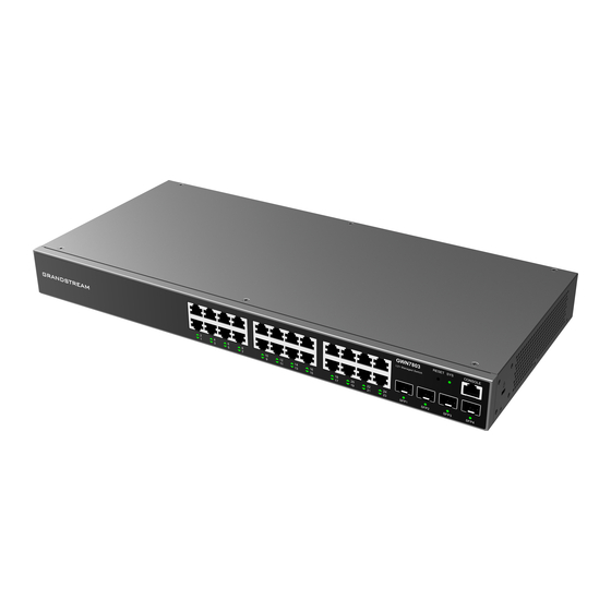
- Page 6 GWN7803/GWN7803P GWN7803/GWN7803P Ports Port & LED Description 24x Ethernet RJ45 (10/100/1000Mbps), used for connecting terminals. Note: GWN7803P Port 1-24 Ethernet ports support PoE and PoE+. 1-24 Ethernet ports’ LED indicators Port SFP1/2/3/4 4x 1000Mbps SFP ports SFP 1/2/3/4 SFP ports’ LED indicators RESET Factory Reset pinhole.
- Page 7 Install on the Desktop GWN780x(P) Desktop Installation 1. Place the bottom of switch on a sufficiently large and stable table. 2. Peel off the rubber protective paper of the four footpads one by one, and stick them in the corresponding circular grooves at the four corners of the bottom of the case.
- Page 8 Install on a 19″ Standard Rack GWN780x(P) L-shaped rack-mounting Installation 1. Check the grounding and stability of the rack. 2. Install the two L-shaped rack-mounting in the accessories on both sides of switch, and fix them with the screws provided (KM 3*6).
- Page 9 2. Put the ground screw back into the screw hole, and tighten it with a screwdriver. 3. Connect the other end of the ground cable to other device that has been grounded or directly to the terminal of the ground bar in the equipment room. Powering on the Switch Connect the power cable and the switch first, then connect the power cable to the power supply system of the equipment room...
- Page 10 3. Wrap the strap of the protective cord around the power cord and lock it tightly. Fasten the straps until the power cord is securely fastened. Connect to SFP Port Connect to RJ45 Port 1. Connect one end of the network cable to the switch, and the other end to the peer device. 2.
- Page 11 Connect to Console Port Connect to Console Port 1. Connect the RJ45 end of the console cable to the console port of switch. 2. Connect the other end of the console cable to the DB9 male connector or USB port to the PC. Safety Compliances The GWN780x(P) L2+ Managed Network Switch complies with FCC/CE and various safety standards.
- Page 12 ● For all ports: port off ● For SFP ports: port failure Solid green Port connected and there is no activity Flashing green Port connected and data is transferring Port Indicator Solid yellow Ethernet port connected, and there is no activity and PoE powered Flashing yellow Ethernet port connected, data is transferring and PoE powered Alternately flashing...
- Page 13 GWN780x(P) WEB GUI Page 1. A PC uses a network cable to correctly connect any RJ45 port of the switch. 2. Set the Ethernet (or local connection) IP address of the PC to 192.168.0.x (“x” is any value between 1-253), and the subnet mask to 255.255.255.0, so that it is in the same network segment with switch IP address.
- Page 14 WEB GUI Configuration Search In case it’s hard to go through every single section, GWN780x(P) Switches have search functionality to help the user find the right configuration, settings or parameters, etc. On the top of the page, there is a search icon, the user can click on it and then enter the keyword relevant to his search, then he will get all the possible locations of that keyword.
- Page 15 System Info page Displays Device and System general information that includes (Device name, MAC Address, Default Basic Info Gateway, System Time, System Version etc.) Resource Status Displays in real time the usage of CPU and Memory. PoE Status Shows the Total Power Consumption and the remaining Power in mA. Diplays the total number of events for each category (Emergency, Alert, Warning etc).
- Page 16 Ethernet Port is Up, PoE is Enabled Ethernet Port is Shutdown, PoE is Disabled PoE Power is UP 1 Gbps speed 10 Gbps speed Ports Labels and Color code There are 3 main sections for each port: Basic Info: displays info about the port name, speed, status etc. Note: Click on to modify the port settings like Description, Speed, Duplex Mode and Flow Control or to enable or disable the port.
- Page 17 It is used to configure the information description of this interface , which can be a description of usage, etc., with a Description maximum of 128 characters, and the characters limited to input are numbers 0-9 , letters az / AZ and special characters.
- Page 18 Flow Statistics Port Auto Recovery Port Auto Recovery helps recover a port after a specific delay that can be specified by the user. When the following functions of the port trigger the port down, the port automatically returns to the up state after the delay time: Examples: ARP packet detection: If the ARP rate in DAI exceeds the set value, the current port will be shut down.
- Page 19 Link Aggregation Group Select your Load balance mode. MAC address - Aggregated group will balance the traffic based on different MAC addresses. Therefore, the Load Balancing packets from different MAC addresses will be sent to different links. Mode IP/Mac Address - Aggregated group will balance the traffic based on MAC addresses and IP addresses. Therefore, the packets from same MAC addresses but different IP addresses will be sent to different links.
- Page 20 Set the rate of the interface, the options are {Auto, 10Mbps, 100Mbps, 1000Mbps}. The default is auto-negotiation. Speed Note: When set to Auto, the rate of the interface is automatically negotiated between the interface and the peer port Set the flow control on the interface, the options are { Disabled, Enabled, Auto}. The default is Disabled After enabling it, if the local device is congested, it will send a message to the peer device to notify the peer device Flow Control to temporarily stop sending packets, after receiving the message, the peer device will temporarily stop sending...
- Page 21 the MAC address table is established based on the automatic learning of the source MAC address in the data frame received by the device. If the MAC address entry does not exist in the MAC address table, the device adds the new MAC address and the interface and VLAN corresponding to the MAC address as a new entry into the MAC address table.
- Page 22 Select the port where received frame of matched destination Port MAC address will be forwarded to. Static MAC Address Black Hole Address If a MAC address is not trusted or insecure, The user can block the traffic of certain MAC Address and discard them by adding them to the Black Hole Address Table.
- Page 23 Add a VLAN If the VLAN is already created there is also the option to modify it by clicking on modify button for more options and settings like Description, Tagged and Untagged ports and LAGs. Edit VLAN VLAN The specified VLAN ID Description Enter a brief comment for the VLAN ID.
- Page 24 default VLAN tag, i.e. the PVID of If the VID of packet is forbidden by The packet will be forwarded with the ingress port, to the packets. the port, the packet will be dropped. Tagged its current VLAN tag VLAN Tagged and Untagged VLAN Port Settings Port Settings page allows for configuring VLAN on each port and LAG by specifying the Link Type (Trunk, Access and Hybrid) as well as the default VLAN or PVID, the user can also enable Ingress Filtering for the selected port, also the accepted Frame...
- Page 25 VLAN Port Members Voice VLAN Voice VLANs are configured specially for voice data stream. By configuring Voice VLANs and adding the ports with voice devices attached to voice VLANs, you can perform QoS-related configuration for voice data, ensuring the transmission priority of voice data stream and voice quality.
- Page 26 An OUI address is a unique identifier assigned by IEEE (Institute of Electrical and Electronics Engineers) to a device vendor. It comprises the first 24 bits of a MAC address. You can recognize which vendor a device belongs to according to the OUI address.
- Page 27 Select the Bridge Priority, In an STP network, the device with the smallest bridge ID is elected as the root bridge. Bridge Priority Default is 32768. Note: The valid range is 0~61440, which must be a multiple of 4096 Max Hops Select the Max Hops (the range is 1 - 40).
- Page 28 Note: The valid range is 0~200000000. 0 is equal to auto Set whether to enable Edge Port or disable it, by default it's on auto. Notes: ● A port is considered as an edge port when it is directly connected to the user terminal or server, instead of any Edge Port other switches or shared network segments.
- Page 29 Edit MST Port Settings MULTICAST IP multicast is a technique for one-to-many communication over an IP infrastructure in a network. To avoid the incoming data broadcasting to all GE/LAG ports, multicast is useful to transfer the data/message to specified GE/LAG ports for IGMP snooping or MLD Snooping.
- Page 30 IGMP Snooping Enable or disable GlobaI IGMP Snooping Set the Multicast Forward Mode. Multicast Forward Mode ● MAC-Based: Forward using MAC address. ● IP-Based: Forward using IP address IGMP Version Select the IGMP Version. Enable or disable the switch to handle IGMP reports Report Suppression between router and host, suppressing bandwidth used by IGMP.
- Page 31 The maximum time interval between counting each member query message with no responses from any subscribed member. Last Member Query Interval (s) Note: The valid range is 1-25 in seconds IGMP Snooping Edit VLAN IGMP Snooping Router Port This page shows the IGMP querier router known to this switch. Click on “Add” to add another one or Click on “Edit” icon to modify already created one.
- Page 32 IGMP Snooping Multicast Port Once the Multicast Policy is created, the user is able to apply this policy on a port. IGMP Snooping Multicast Port MLD Snooping MLD Snooping Global Settings As an IPv6 Layer 2 multicast protocol, MLD Snooping maintains the outgoing port information of multicast packets by listening to the multicast protocol packets sent between Layer 3 multicast devices and user hosts, so as to manage and control multicast data .
- Page 33 ● IP-Based: Forward using IP address MLD Version Select the MLD Version. Enable or disable the switch to handle MLD reports Report Suppression between router and host, suppressing bandwidth used by MLD. MLD Snooping Global Settings Once Global MLD Snooping is enabled, then the user can enable more settings per VLAN. MLD Snooping –...
- Page 34 MLD Snooping Router Port If the router port is statically configured, the Layer 2 device will also forward the MLD report and leave message to the static router port. If a static member port is configured, the interface will be added as the outgoing interface in the forwarding table. After a Layer 2 multicast forwarding table entry is established on a Layer 2 device, when the Layer 2 device receives a multicast data packet, it searches for the forwarding table according to the VLAN to which the packet belongs and the destination address of the packet (that is, the IPv6 multicast group address).
- Page 35 MLD Snooping Multicast Port The multicast policy can be applied to Gigabit Ethernet/LAG port, the user can also set the maximum number of multicast groups that the port is allowed to join and set the action when the port multicast exceeds the limit, the default is rejected . MLD Snooping Multicast Port Over Ethernet (PoE) refers to supplying power over an Ethernet network , also known as a local area network-based power supply system PoL or Active Ethernet.
- Page 36 PoE – Global – Settings Application scenarios: The device will dynamically allocate power to each interface according to the power actually consumed by each interface. During the running process of each PD device, its power consumption will continue to change, and the system will periodically calculate the total power required by all currently connected PDs.
- Page 37 QoS – Port Priority Port Priority Select whether to enable Port Priotiy. (Default is disabled) Select the QoS operation mode: ● CoS: Traffic is mapped to queues based on the CoS Queue Mapping, it can configured in QoS → Priority Mapping → CoS Mappging page. ●...
- Page 38 CoS Mapping DSCP Mapping Shows the mapping relationship between DSCP values and queue priorities. DSCP Mapping IP Mapping Shows the mapping relationship between IP priority and queue. IP Mapping Queue Scheduling When congestion occurs in the network, the device will determine the processing order of forwarding packets according to the specified scheduling policy, so that high-priority packets are preferentially scheduled.
- Page 39 Weighted Round Robin ( WRR, Weighted Round Robin) scheduling: each priority queue is allocated a certain bandwidth, and provides services for each priority queue according to the priority from high to low. When the high- priority queue has used up all the allocated bandwidth, it is automatically switched to the next priority queue to serve it. Queue Scheduling Queue Shaping When the packet sending rate is higher than the receiving rate, or the interface rate of the downstream device is lower than...
- Page 40 SECURITY GWN780x(P) Switches series support many tools and features to enhance the security of the device against misconfiguration or attacks. Storm Control Traffic suppression can limit the rate of broadcast, unknown multicast , unknown unicast, known multicast, and known unicast packets by configuring thresholds , preventing broadcast, unknown multicast packets, and unknown unicast packets from generating broadcast storms.
- Page 41 Set whether to enable the storm threshold setting for the Unknown Multicast packets If Enabled Please enter a Treshhold (Kbps). Unknown Multicast Note: The valid range is 16~1000000, which must be a multiple of 16. Default is 10000. Set whether to enable the storm threshold setting for the Unknown Unicast packets. If Enabled Please enter a Treshhold (Kbps).
- Page 42 Port Security Address Click to enable Port Security Address, by default is disabled. Set the maximum number of MAC addresses to be learned by the interface , the value range is an integer from 1 to 256 , and the default is 1 . After the maximum number is reached , if the switch Maximum MAC Number receives a packet whose source MAC address does not exist, regardless of whether the destination MAC address exists, the switch considers that there is an attack by an illegal user, and will protect the...
- Page 43 filters out specific packets , and allows or organizes the packets to pass through according to the processing policy of the service module that applies the ACL. Notes: One ACL supports setting multiple rules . When the rule settings (except the rule number ) are identical, it will prompt ” This rule already exists”...
- Page 44 MAC ACL ACL Binding ACL Binding lets the user bind MAC ACL or IP ACL to a certain ports GE/LAG. ACL Binding IP Source Guard IP source guard attack is a source IP address filtering technology based on Layer 2 interface. It can prevent malicious hosts from forging IP addresses of legitimate hosts to impersonate legitimate hosts, and also ensure that unauthorized hosts cannot access by specifying their own IP addresses.
- Page 45 Quaternary Binding Table Anti Attack In the network , there are a large number of malicious attack packets targeting the CPU and various types of packets that need to be normally sent to the CPU. Malicious attack packets targeting the CPU will cause the CPU to be busy processing attack packets for a long time, thereby causing interruption of other services or even system interruption ;...
- Page 46 The statistics about DAI activities will be listed here for each port GE/LAG with the options of refreshing the statistics or clearing specified port data. DAI Statistics RADIUS RADIUS is a distributed, client /server information exchange protocol that can protect the network from unauthorized access. It is often used in various network environments that require high security and allow remote users to access.
- Page 47 and accounting of access users who access the Internet by means of point-to-point protocol PPP or virtual private dial-up network VPDN and management users who perform operations. TACACS+ is similar to RADIUS protocol : ( 1 ) both adopt client /server mode in structure; (2) both use shared key to encrypt the transmitted user information ;...
- Page 48 reduce network construction costs. Authentication packets and data packets are separated through logical interfaces to improve security. 802.1X Port Mode 802.1X Port 802.1X Port DHCP Snooping DHCP snooping ensures that DHCP clients obtain IP addresses from legitimate DHCP servers, and records the correspondence between IP addresses and MAC addresses of DHCP clients to prevent DHCP attacks on the network.
- Page 49 Circuit id is used to identify the VLAN, interface and other information where the client is located. DHCP Option 82 DHCP Port Settings This page allows a user to configure detailed settings of DHCP Snooping for each port (GE/LAG). Any device that is not in the service provider network will be regarded as an entrusted source (such as a customer switch). DHCP Port Settings DHCP Statistics This page displays all statistics recorded by DHCP snooping function.
- Page 50 SNMP is a component of the Internet Protocol Suite as defined by the Internet Engineering Task Force (IETF). It consists of a set of standards for network management, including an application layer protocol, a database schema, and a set of data objects.
- Page 51 SNMP – View Management Group Management This page allows the network administrator to group SNMP users and assign different authorization and access privileges. SNMP – Group Management Community Management This page allows a user to add/remove multiple communities of SNMP. SNMP –...
- Page 52 SNMP – User Management Notification Management This page allows a user to configure a host to receive SNMPv1/v2/v3 notification. SNMP – Notification Management Trap Event This page allows a user to add or delete SNMP trap receiver IP address and community name. SNMP –...
- Page 53 Diagnostics – Logs Adding a Log Server Address to the logs to be sent to is also supported on the GWN780x(P) Switches. Log Server Address Ping The user in this page can enter the IP Address or Hostname then click “Start”, the results of the ping command will be shown below.
- Page 54 Traceroute Port Mirroring Mirroring refers to copying the packets from the specified source to the destination port. The specified source is called the mirroring source, the destination port is called the observing port , and the copied packet is called the mirroring packet. Mirroring can make a copy of the original packet without affecting the normal processing of the original packet by the device, and send it to the monitoring device through the observation port to determine whether the service running on the network is normal.
- Page 55 RMON Statistics Ethernet statistics function ( corresponding to the statistics group in the RMON MIB) : The system collects basic statistics of each network being monitored. The system will continuously count the traffic of a certain network segment and the distribution of various types of packets, or the number of error frames of various types , the number of collisions , etc.
- Page 56 RMON Alarm The system monitors the specified alarm variable. After pre-defining a set of thresholds and sampling time for the specified alarm, the system will obtain the value of the specified alarm variable according to the defined time period. When the value of the alarm variable is greater than or equal to the upper threshold, an upper alarm event will be triggered.
- Page 57 LLDP Port Settings LLDP MED Network Policy This page allows the network administrator to set MED (Media Endpoint Discovery) network policy. Click on “Add” button to add a Network Policy. LLDP MED Network Policy LLDP MED Port Settings The user can configure LLDP MED Settings for each port in this page. LLDP MED Port Settings LLDP Device Info This page displays information for LLDP Local Device connected to each port.
- Page 58 LLDP Device Info Neighbor Info This page lists the neighbors obtained on the switch ports. Click on “Refresh” button to update the list. LLDP Neighbor Info LLDP Statistics View the LLDP statistics of the local device through this feature. Click on “Refresh” to update the list. LLDP Statistics UPGRADE AND PROVISIONING Upgrade...
- Page 59 Upgrade Backup and Restore Click on “Factory Reset” button to reset the GWN780x(P) Switch back to default settings, or restore to previously saved backup by uploading a configuration file, these configuration files can be used as a way to back up the device running configuration or saved configuration.
- Page 60 Type the switch’s default management IP address http://<gwn780x(P)> in the browser, and enter username and password to login. (The default administrator username is “admin” and the default random password can be found at the sticker on the GWN7800 switch). Login Service On the second page (Access Control), the user can specify the Web Idle Timeout before the web page auto lock, and also enabling Telnet or SSH.
- Page 61 User Management CHANGE LOG This section documents significant changes from previous versions of the GWN780x(P) switches user manuals. Only major new features or major document updates are listed here. Minor updates for corrections or editing are not documented here. Firmware Version 1.0.1.30 Product Name: GWN7801(P) / GWN7802(P) / GWN7803(P) No major changes Firmware Version 1.0.1.20...
Need help?
Do you have a question about the GWN780 Series and is the answer not in the manual?
Questions and answers