Table of Contents
Advertisement
Quick Links
Advertisement
Table of Contents

Related Manuals for Grandstream Networks GWN771 Series


Summary of Contents for Grandstream Networks GWN771 Series
- Page 1 Grandstream Networks, Inc. GWN771x Series GWN771x Layer 2 lite – User Manual...
-
Page 2: Product Overview
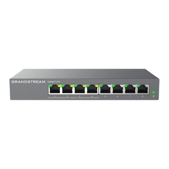
The GWN7711(P) Series are Layer 2 lite managed network switches that enable small to medium-sized businesses to build scalable, secure, high-performance, intelligent business networks that are easy to use and manage. It supports VLAN for flexible and sophisticated traffic segmentation, QoS for prioritizing network traffic, IGMP snooping for optimizing network performance, and comprehensive security features against potential attacks. - Page 3 Forwarding Rate 11.9Mpps 8K MAC address capacity ● 4K VLANs VLAN ● Port-based VLAN, 802.1Q VLAN Multicast IGMP Snooping, Report Message Suppression ● Auto prioritization of the incoming port of the packet ● Priority Mapping ● Queue scheduling, including SP, WRR, WFQ ●...
-
Page 4: Installation
GWN7711(P) Technical Specifications INSTALLATION Before deploying and configuring the GWN7711(P) switch, the device needs to be properly powered up and connected to the network. This section describes detailed information on the installation, connection, and warranty policy of the GWN7711(P) switch. Package Contents GWN7711(P) package contents GWN7711 Ports... -
Page 5: Getting Started
GWN7711P Grounding the switch 1. Remove the ground screw from the back of the switch, and connect one end of the ground cable to the wiring terminal of the switch. 2. Put the ground screw back into the screw hole, and tighten it with a screwdriver. 3. -
Page 6: Webui Configuration
Not providing PoE power. Standard PoE normal power supply (connect PD to negotiate power Solid yellow supply); 24V or 48V forced-mode PoE power PoE LED (GWN7711P) supply. PoE power supply anomaly (Port Overload / 24V Flashing yellow Throttling / PSE Throttling). -
Page 7: System Info
WebUI configuration Search GWN7711(P) Switches have search functionality to help the user find the right configuration, settings, parameters, etc. On the top of the page, there is a search icon, the user can click on it and then enter the keyword relevant to his search, and then he will get all the possible locations of that keyword. - Page 8 System Info Port Info This page displays the status for each port on the GWN7711(P) switches indicated by color code (green, red, grey, white, etc) and PoE symbol. Please refer to the figure below: Port Info page The following table explains the color code and the symbols used: Grey: Linkdown White: shutdown Green: 1000 Mbps speed...
-
Page 9: Port Settings
Ports Labels and Color code Note: a PoE symbol and color code combination is also possible. Ex: in this case, the port is using 1000 Mbps speed and also using PoE at the same time. There are 3 main sections for each port: Basic Info: displays info about the port name, speed, status etc. - Page 10 Port Settings To configure a port, click on the “Edit” icon under the operation column. Port Settings – Edit port Port The selected Port to be configured. It is used to configure the information description of this interface , which can be a description of usage, etc., with a Description maximum of 32 characters, and the characters limited to input are numbers 0-9 , letters az / AZ and special characters.
-
Page 11: Jumbo Frame
packets to the local and vice versa. Thus, the occurrence of packet loss is avoided. Port Settings – Edit port Jumbo Frame The maximum Transmission Payload or MTU is typically 1500 bytes, in case the user requires even a bigger MTU length for a specific scenario, there is an option on the GWN7711(P) Switch to enable Jumbo Frame, the maximum Ethernet frame size ranges from 2K up to 15K. -
Page 12: Mac Address Search
Member Port Click on ports to be part of this LAG group. It is used to configure the information description for this LAG , which can be a description of usage, etc., with a Description maximum of 32 characters, and the characters limited to input are numbers 0-9 , letters az / AZ and special characters. - Page 13 Port VLAN On this page, the user can select which VLANs (a preset from 1 to 8) can be allowed on GWN7711(P) ports. This is a simplified way to manage VLAN from 1 to 8. To have more flexibility and control, please enable 802.1Q VLAN and Port VLAN will be disabled automatically.
- Page 14 802.1Q VLAN On this screen, the user can configure the VLAN: VLAN: specify the VLAN ID (Range 2-4094). Description: enter a description for the VLAN. Member Type: a shortcut to untag/tag or remove all members. Physical port: select the tagged/untagged ports accordingly. 802.1Q VLAN –...
-
Page 15: Igmp Snooping
802.1Q PVID Settings – edit port IGMP SNOOPING The GWN7711(P) switches support IGMP snooping, which is an IPv4 Layer 2 multicast protocol that optimizes the handling of multicast traffic in a network by intelligently forwarding traffic only to the ports where interested hosts are located, based on the monitoring of IGMP messages. -
Page 16: Qos Basic Settings
The popularity of the network and the diversification of services have led to a surge in Internet traffic, resulting in network congestion, increased forwarding delay, and even packet loss in severe cases, resulting in reduced service quality or even unavailability. Therefore, to carry out these real-time services on the network, it is necessary to solve the problem of network congestion. -
Page 17: Priority Mapping
Priority Mapping Priority mapping is used to realize the conversion between the QoS priority carried in the packet and the internal priority of the device ( also known as the local priority, which is the priority used by the device to differentiate the service level of the packet ) so that the device provides the Differentiated QoS service quality. - Page 18 Strict priority (SP) scheduling: The flow with the highest priority is served first, and the flow with the second highest priority is served until there is no flow at that priority. Each interface of the switch supports 8 queues ( queues 0-7 ), queue 7 is the highest priority queue, and queue 0 is the lowest priority queue. Disadvantage: When congestion occurs, if there are packets in the high-priority queue for a long time, the packets in the low-priority queue cannot be scheduled, and data cannot be transmitted.
-
Page 19: Rate Limit
Queue Scheduling – Edit Rate Limit Interface rate limit can limit the total rate of all packets sent or received on an interface. The interface rate limit also uses the token bucket to control the flow. If an interface rate limit is configured on an interface of the device, all packets sent through this interface must first be processed through the token bucket of the interface rate limiter. -
Page 20: Storm Control
Rate Limit – Edit port Storm Control The GWN7711(P) switches support a storm control feature that prevents broadcast, unknown multicast, or unknown unicast by monitoring and limiting excessive traffic on a port. It helps prevent network congestion and performance problems caused by an overwhelming amount of packets. - Page 21 Storm Control – Edit a port Select Unit: Unit ● kbps: Storm control rate will be calculated by octet-based. ● pps: Storm control rate will be calculated by packet-based. Select IFG (Inter Frame Gap): ● Excluded: Exclude IFG when count ingress storm control rate. ●...
-
Page 22: Power Supply Setting
Power Supply Info This page Displays the Power Supply Info like the number of PoE, Total, Remaining PoE Power, etc, and even the Supply Voltage. Power Supply Info Power Supply Setting On this page, the user can configure the total power input and configure PoE on each port that supports PoE. On the GWN7711P switch model, the ports 1-4 support PoE/PoE+. -
Page 23: Port Statistics
MONITORING Port Statistics For monitoring or even sometimes troubleshooting, the Flow Statistics displays in real time the flow of data with different units like Octects, Packets, Transmission Rate, and OutErrPackets. To refresh the statistics, click on the “Refresh” button, and to clear all the statistics click on the “Clear All” button. To clear the data for a specific port click on the “clear icon”... -
Page 24: Cable Test
Port Mirror To start mirroring a port, first select the Ingress (incoming traffic to the switch) Mirroring port, then select the Egress (outgoing traffic) Mirroring port, and then select from the drop-down list the Monitor port (Monitor port cannot be the same as the Mirroring port), please refer to the figure below: Port Mirror –... -
Page 25: Loopback Detection
Loopback Detection The GWN7711(P) switches support loopback detection, a feature commonly used in computer networking to identify and mitigate network loops that can cause broadcast storms and negatively impact network performance. Network loops occur when there is more than one path between switches on a network and data circulates endlessly, consuming network bandwidth and potentially causing network outages. -
Page 26: Change Log
Restore: The switch configuration can be restored based on the imported configuration file. If the device fails to be restored, hold down the Pinhole button on the back of the switch for five seconds to restore the switch to factory settings. Factory Reset: After factory restoration, all configurations of the switch will be restored to factory defaults.
Need help?
Do you have a question about the GWN771 Series and is the answer not in the manual?
Questions and answers