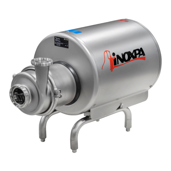
INOXPA HYGINOX SE-15 Installation, Service And Maintenance Instructions
Centrifugal pump
Hide thumbs
Also See for HYGINOX SE-15:

Related Manuals for INOXPA HYGINOX SE-15


Summary of Contents for INOXPA HYGINOX SE-15
- Page 1 INSTALLATION, SERVICE AND MAINTENANCE INSTRUCTIONS CENTRIFUGAL PUMP HYGINOX SE Original Instructions 01.011.30.11EN (0) 2023/03...
- Page 2 INOXPA S.A.U. Telers, 60 17820 - Banyoles (Spain) hereby declare under our sole responsibility that the CENTRIFUGAL PUMP Machine: HYGINOX SE Model: HYGINOX SE-15, HYGINOX SE-20, Type: HYGINOX SE-26, HYGINOX SE-28, HYGINOX SE-35, HYGINOX SE-36 IXXXXXXXXX IXXXXXXXXX Serial number: XXXXXXXXXIINXXX...
- Page 3 INOXPA S.A.U. Telers, 60 17820 - Banyoles (Spain) hereby declare under our sole responsibility that the CENTRIFUGAL PUMP Machine: HYGINOX SE Model: HYGINOX SE-15, HYGINOX SE-20, Type: HYGINOX SE-26, HYGINOX SE-28, HYGINOX SE-35, HYGINOX SE-36 IXXXXXXXXX IXXXXXXXXX Serial number: XXXXXXXXXIINXXX...
-
Page 4: Table Of Contents
1. Table of Contents 1. Table of Contents 2. Generalities 2.1. Instructions manual ............................5 2.2. Compliance with the instructions ........................5 2.3. Warranty ................................5 3. Safety 3.1. Warning symbols ..............................6 3.2. General safety instructions ..........................6 4. General Information 4.1. -
Page 5: Generalities
The non-compliance of the prescribed indications in this manual means misuse of this gear on the technical side and the personal safety and this, exempts INOXPA of all responsibility in case of accidents and personal injuries and/or property damage. Also, excluded from the warranty all breakdowns caused by improper use of the gear. -
Page 6: Safety
ATTENTION 3.2. GENERAL SAFETY INSTRUCTIONS Read the instruction manual carefully before installing and starting the pump. Contact INOXPA in case of doubt. 3.2.1. During installation Always take into account the Technical Specifications of chapter 9. Never start the pump before connecting it to the lines. - Page 7 ALWAYS disconnect the electrical power to the pump prior to carrying out any mainte- nance. Remove the fuses and disconnect the cable from the motor’s terminals. All electrical work must be carried out by authorized personnel. INOXPA S.A.U. 01.011.30.11EN · (0) 2023/03...
-
Page 8: General Information
Misuse or its use beyond the operating limits may be dangerous or cause permanent damage to the equipment. INOXPA shall not be liable for any damage resulting from the incompleteness of the in- formation provided by the purchaser (nature of the fluid, rpm, etc.) INOXPA S.A.U. -
Page 9: Installation
Installation 5. Installation 5.1. RECEPTION OF THE PUMP INOXPA cannot be held responsible for the damage sustained by the equipment during transport or unpacking. Please visually check that the packaging is not damaged. The pump package includes the following documents:... -
Page 10: Transport And Storage
Place the pump in a position that allows enough space around it to provide access to the pump as well as to the motor. For the pumps with legs, consult in chapter 9. Technical Specifications the di- mensions and the weights of the pump. For the pumps with double mechanical seal and without legs, respect the minimum distance respect to the floor represented in the following figure: INOXPA S.A.U. 01.011.30.11EN · (0) 2023/03... -
Page 11: Pipes
- place the pump as close as possible to the suction tank and whenever possible below the liquid level or even below the tank level in order to achieve the largest possible static head for suction, INOXPA S.A.U. 01.011.30.11EN · (0) 2023/03... -
Page 12: Double Mechanical Seal Connection
EN 60204-1, - check the direction of rotation (see the signalling label on the pump), - start and stop the pump motor momentarily. Make sure, looking at the pump by the hopper side, that the rotation direction of the motor fan is counterclockwise. INOXPA S.A.U. 01.011.30.11EN · (0) 2023/03... - Page 13 Installation ATTENTION See the indicator label on the pump. ALWAYS check the direction of rotation of the motor with liquid inside the pump. INOXPA S.A.U. 01.011.30.11EN · (0) 2023/03...
-
Page 14: Start-Up
Start-up 6. Start-up Before starting the pump, carefully read the instructions in section 5. Installation. Carefully read section 9. Technical Specifications. INOXPA will not be liable for improper use of the equipment. NEVER touch the pump or the lines of hot liquids that are being mixed. 6.1. CHECKS BEFORE STARTING THE PUMP Before starting the pump:... - Page 15 Start-up Use special protection when the sound pressure in the operation area exceeds 85 dB(A). INOXPA S.A.U. 01.011.30.11EN · (0) 2023/03...
-
Page 16: Troubleshooting
The following table provides solutions to problems that might arise during the operation of the pump. The pump is assumed to have been properly installed and be suitable for the relevant application. Please contact INOXPA if technical assistance is required. Motor overload The pump does not provide enough flow or pressure... -
Page 17: Maintenance
The period between each preventive maintenance service will vary depending on the operating condition of the pump: temperature, flow, number of operating hours, cleaning solutions used, etc. 8.4. TIGHTENING TORQUE Size lbf·ft 8.5. STORAGE Before being stored the pump must be completely emptied of liquids. Avoid, as far as possible, the exposure of the parts to excessively damp atmospheres. INOXPA S.A.U. 01.011.30.11EN · (0) 2023/03... -
Page 18: Cleaning
Maximum conditions during the steam or overheated water SIP process: a. maximum temperature: 140ºC / 284ºF b. maximum time: 30 min c. cooling: sterile air or inter gas d. materials: EPDM (recommended) FPM (use with caution) INOXPA S.A.U. 01.011.30.11EN · (0) 2023/03... -
Page 19: Disassembly And Assembly Of The Pump
Incorrect assembly or disassembly may cause damage in the blender’s operation and lead to high repair costs and a long period of downtime. INOXPA is not responsible for accidents or damages cause by a failure to comply with the instructions in this manual. - Page 20 6. Remove rotating part mechanical seal (08) from the back part of the impeller (02). 7. Remove the cover pump (03) from the lantern (04). 8. Manually remove the stationary part of the mechanical seal (08) from the pump cover. 9. Remove the splash ring (82) from the shaft (05). 10. Place the shaft (05) so the two studs (55) are at the bottom part and loosen them with an allen screw. 11. Remove the shaft (05) from the motor (93). INOXPA S.A.U. 01.011.30.11EN · (0) 2023/03...
- Page 21 13. Place the pump casing (01) and fix the lantern (04) with the clamping ring (15) and tighten the nut strongly. ATTENTION When installing the new seal, use soapy water when fitting the different parts and gas- kets to allow them to slide better. Apply to the stationary as well as the rotating parts. INOXPA S.A.U. 01.011.30.11EN · (0) 2023/03...
- Page 22 9. Remove the stationary part of the double mechanical seal (08A). 10. Remove the splash ring (82) del eje (05). 11. Place the shaft (05) so the two studs (55) are at the bottom part and loosen them with a 4 mm allen screw in order to remove the shaft (05). INOXPA S.A.U. 01.011.30.11EN · (0) 2023/03...
- Page 23 Maintenance 12. Loose the screws (51B) and remove them with their grower washers (53C). 13. Separate stationary parts of the mechanicals seals (08,08A) from the pump cover (03), double mechanical seal cover (10) and the O-ring (80C). INOXPA S.A.U. 01.011.30.11EN · (0) 2023/03...
- Page 24 9. Mount the impeller (02) on the shaft, fix it with the impeller nut (45) and gauge the assembly position according to picture 01.011.32.0030. 10. Tighten the studs (55) that fix the shaft (05) to the motor (93). 11. Unscrew the impeller nut (45) and remove the impeller (02) and the cover (03). INOXPA S.A.U. 01.011.30.11EN · (0) 2023/03...
- Page 25 19. Place the pump casing (01) and fix the lantern (04) with the clamping ring (15) and tighten the nut strongly. ATTENTION When installing the new seal, use soapy water when fitting the different parts and gas- kets to allow them to slide better. Apply to the stationary as well as the rotating parts. INOXPA S.A.U. 01.011.30.11EN · (0) 2023/03...
-
Page 26: Technical Specifications
The indicated noise levels correspond to the standard pump, with maximum impeller and shrouded motor, running at approximately 2900 rpm, at the point of best efficiency and with a motor with suffi- cient power. These values were taken at a distance of 1 m from the pump and at a height of 1,6 m above the floor level. The measurements were carried out according to the standard EN 12639 / ISO 3746 Grade 3 with a tolerance of ±3 dB(A). INOXPA S.A.U. 01.011.30.11EN · (0) 2023/03... -
Page 27: Weights
9.2. WEIGHTS Weight (kg) 0,25 0,37 0,55 0,75 1,1 SE-15 SE-20 SE-26 SE-28 SE-35 100 136 156 SE-36 103 138 158 9.3. DIMENSIONS B Motor Dimensions (mm) Pump ØB 0,25 0,37 0,55 SE-15 0,75 INOXPA S.A.U. 01.011.30.11EN · (0) 2023/03... - Page 28 Technical Specifications Motor Dimensions (mm) Pump ØB SE-20 SE-26 SE-28 SE-35 SE-36 INOXPA S.A.U. 01.011.30.11EN · (0) 2023/03...
-
Page 29: Exploded Drawing
Technical Specifications 9.4. EXPLODED DRAWING 52B,53C 53D,54A 53B,51 Detail pump with motor T132/166 INOXPA S.A.U. 01.011.30.11EN · (0) 2023/03... - Page 30 O-ring EPDM O-ring O-ring EPDM O-ring EPDM splash ring EPDM motor 1) Recommended spare parts Piezas solo para bombas con tamaño de motor 132 y 160 Position Description Quantity Material counterflange hexagonal screw flat washer INOXPA S.A.U. 01.011.30.11EN · (0) 2023/03...
-
Page 31: Double Mechanical Seal
Technical Specifications 9.5. DOUBLE MECHANICAL SEAL Position Description Quantity Material double mechanical seal double mechanical seal cover 1.4404 (AISI 316L) allen screw grower washer O-ring EPDM coupling 1.4301 (AISI 304) rotary male bend for tube Ø8 mm 1) Recommended spare parts INOXPA S.A.U. 01.011.30.11EN · (0) 2023/03... - Page 32 How to contact INOXPA S.A.U.: Contact details for all countries are continually updated on our website Please visit www.inoxpa.com to acces the information. INOXPA S.A.U. Telers, 60 - 17820 - Banyoles - Spain...
Need help?
Do you have a question about the HYGINOX SE-15 and is the answer not in the manual?
Questions and answers