
Related Manuals for INOXPA SLR Series


Summary of Contents for INOXPA SLR Series
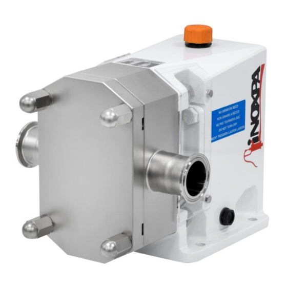
- Page 1 INSTALLATION, SERVICE AND MAINTENANCE INSTRUCTIONS LOBE PUMP Original Instructions 01.500.30.03EN (0) 2019/12...
- Page 2 Regulation (EC) 1935/2004 In compliance with relating to materials and articles intended to come into contact with food. The technical file has been prepared by the signer of this document in INOXPA S.A.U. David Reyero Brunet Technical Office Manager Banyoles, 30...
-
Page 3: Table Of Contents
8.9. Adjusting and synchronising the lobes ....................... 26 8.10.Assembly / disassembly of the mechanical seal ..................28 9. Technical Specifications 9.1. Tightening torque ............................38 9.2. Particle size ..............................39 9.3. Weights ............................... 39 9.4. Dimensions ..............................40 INOXPA S.A.U. 01.500.30.03EN · (0) 2019/12... - Page 4 9.7. SLR 2-40 / 2-50 ............................46 9.8. SLR 3-50 / 3-80 ............................48 9.9. SLR 4-100 / 4-150 ............................50 9.10.SLR 5-125 / 5-150 ............................. 52 9.11.Relief valve ..............................54 9.12.Front heating jacket ........................... 55 INOXPA S.A.U. 01.500.30.03EN · (0) 2019/12...
-
Page 5: Generalities
• risk to the environment due to the type of substances released. 2.3. WARRANTY Any warranty will be void immediately and lawfully and, additionally, INOXPA will be compensated for any civil liability claims submitted by third parties, in the following cases: •... -
Page 6: Safety
Important instruction for the protection of the equipment and its functions ATTENTION 3.2. GENERAL SAFETY INSTRUCTIONS Read the instruction manual carefully before installing and starting the pump. Contact INOXPA in case of doubt. During the installation Technical specifications of chapter 9 should always be observed. - Page 7 ALWAYS disconnect the electrical power to the pumps prior to carrying out any maintenance. Remove the fuses and disconnect the cable from the motor’s terminals. All electrical work must be carried out by authorized personnel. INOXPA S.A.U. 01.500.30.03EN · (0) 2019/12...
-
Page 8: General Information
4.3. APPLICATION The main advantage of the INOXPA lobe pump is its capacity to pump a great variety of viscous liquids, from 1 mPa.s up to 100.000 mPa.s. Furthermore, it is capable of pumping liquid products that require very careful handling and liquids that contain soft solids with only a minimum degradation of same. -
Page 9: Installation
5. Installation 5.1. RECEPTION OF THE PUMP INOXPA will not be liable for any deterioration of the material due to transport of unpacking. Visually check that the packaging has not been damaged. The following documentation is included with the pump: •... -
Page 10: Transport And Storage
• Grout. • When the grout has entirely hardened the pump unit can be placed on the baseplate or the frame. Tighten the nuts on the foundation bolts carefully. For other foundations consult INOXPA. INOXPA S.A.U. 01.500.30.03EN · (0) 2019/12... -
Page 11: Coupling
• Repeat the check, but this time on both sides of the coupling near the shaft. Maximum alignment deviations: Outside diameter of Va max. - Va min. the coupling [mm] [mm] [mm] [mm] 0,20 0,25 0,25 0,30 0,35 0,40 0,45 0,50 INOXPA S.A.U. 01.500.30.03EN · (0) 2019/12... -
Page 12: Pipes
The by-pass should not lead back to the intake orifice but to the supply tank instead.. INOXPA S.A.U. 01.500.30.03EN · (0) 2019/12... -
Page 13: Secondary Piping
Flushed mechanical seal / Quench If the mechanical seal requires flush media, is not the responsibility of INOXPA the media supply and the purchase and installation of piping. -
Page 14: Relief Valve (Pressure Bypass)
Remember that the pressure relief valve is not able to be used to regulate the flow rate. 5.9. ELECTRICAL INSTALLATION Only qualified personnel can connect the electric motors. Take the necessary measures to prevent damage to cables and connections. INOXPA S.A.U. 01.500.30.03EN · (0) 2019/12... - Page 15 ALWAYS check the direction of rotation of the motor with liquid inside the pump. For models with a seal chamber, ALWAYS ensure that it is full of liquid prior to checking the direction of rotation. INOXPA S.A.U. 01.500.30.03EN · (0) 2019/12...
-
Page 16: Start-Up
Prior to starting the pump, carefully read the instructions in section Installation. Carefully read section 9. Technical specifications. INOXPA will not be liable for improper use of the equipment. NEVER touch the pump or the lines if hot liquids are being pumped. 6.1. CHECKS BEFORE STARTING THE PUMP ... - Page 17 When the desired opening pressure has been set, tighten the nut (54C). ATTENTION If the relief valve is not working properly, the pump must be put out of service immediately. The valve must be checked by INOXPA’s technical service personnel. Tamaño 2-5 bar...
-
Page 18: Troubleshooting
The attached table lists solutions to problems that may arise while operating the pump. It is assumed that the pump has been properly installed and that is has been selected correctly for the specific application. Contact INOXPA if technical assistance is required. Motor overload... -
Page 19: Maintenance
Regularly check that there are no leaks and that the pump is operating correctly. Scheduled maintenance Keep a record of the pump. Use statistics to plan inspections. During assembly, use soapy water when fitting the different gaskets to Lubrication allow them to slide better. INOXPA S.A.U. 01.500.30.03EN · (0) 2019/12... -
Page 20: Oiling
If the drive screw gasket (80) or sleeve seal gasket (80B) is damaged, the threads of the shafts (05 and 05A) and the screws (25) must be cleaned. It is recommended: 1. Remove the screws (25), washers (35) and lobes (02) according to the instructions given in section 8.7.2. Disassembly the lobes. INOXPA S.A.U. 01.500.30.03EN · (0) 2019/12... -
Page 21: Disassembly Of The Pump
Incorrect assembly or disassembly may cause damage in the pump’s operation and lead to high repair costs and a long period of down time. INOXPA is not responsible for accidents or damages cause by a failure to comply with the instructions in this manual. - Page 22 Disassembly the lobes • Unscrew the lobe screws (25) using a wrench (see the fig.: 01.500.32.0059). This wrench can be ordered from INOXPA. • These screws are threaded to the right. Wooden or nylon blocks can be placed between the lobes to stop them from rotation.
- Page 23 • Check the klingerit seal (18A) –or O-ring (80E) on the support of size 4– after that the shaft assembly is has removed. If there is any defect, look for a spare seal before to assembly the pump. INOXPA S.A.U. 01.500.30.03EN · (0) 2019/12...
-
Page 24: Assembly Of The Pump
Hit slightly the housing until to adjust to bearing bracket. • Tighten the Allen screws (51B). • Tighten the screws with appropriate tightening torque. INOXPA S.A.U. 01.500.30.03EN · (0) 2019/12... - Page 25 • Tighten the screws (25) with a key. To prevent the lobes form turning simultaneously, the extraction tool handle can be used (this tool can be ordered from INOXPA). • The assembly is exactly the same for the all types of lobes.
-
Page 26: Adjusting And Synchronising The Lobes
B = axial play between lobe and rear side of the body C = axial play between lobe and body D = radial play between lobes E = radial play between lobe and body in the suction INOXPA S.A.U. 01.500.30.03EN · (0) 2019/12... - Page 27 • Remove the lobes (02) from the shafts (05 and 05A). • Apply a small amount of lubricant to the drive shaft (05) in the area of the retainer ring (88) once you have completed the assembly process. INOXPA S.A.U. 01.500.30.03EN · (0) 2019/12...
-
Page 28: Assembly / Disassembly Of The Mechanical Seal
• Clean all the mechanical seal components prior to installing them. • Check that the working surfaces are not damaged. INOXPA recommends replacing all of the mechanical seals if one of the working surfaces is found to have some defect. - Page 29 • Mount the body (01) in the bearing bracket (06). See chapter 8.8.3. Assembly of the body / seal cover. • See chapter 8.9.4. Adjustment of the lobes / pump body using spacer washers. INOXPA S.A.U. 01.500.30.03EN · (0) 2019/12...
- Page 30 • Clean all the mechanical seal components prior to installing them. • Check that the working surfaces are not damaged. INOXPA recommends replacing all of the mechanical seals if one of the working surfaces is found to have some defect.
- Page 31 • Clean all the mechanical seal components prior to installing them. • Check that the working surfaces are not damaged. INOXPA recommends replacing all of the mechanical seals if one of the working surfaces is found to have some defect.
- Page 32 • Mount the quench cover (10) with the lip seal (88A) with the screws (51B). • Mount the stationary part of the flushed mechanical seal in the seal cover (09), trying that it is completely flat. INOXPA S.A.U. 01.500.30.03EN · (0) 2019/12...
- Page 33 Clean all the retainer ring components prior to installing them. • Check that the working surfaces are not damaged. INOXPA recommends replacing all of the mechanical seals if one of the working surfaces is found to have some defect.
- Page 34 (80B). • Place the sleeve (13A) o (13D) on the shaft. • Place the cover seal assembly (09) on the body (01). • Fix them with the safety nut (57) on the body (01). INOXPA S.A.U. 01.500.30.03EN · (0) 2019/12...
- Page 35 • Clean all the lip seal components prior to installing them. • Check that the working surfaces are not damaged. INOXPA recommends replacing all of the mechanical seals if one of the working surfaces is found to have some defect.
-
Page 36: Technical Specifications
Maximum temperature in continual, EPDM seals and standard settings. If the temperature is higher, consult with INOXPA The maximum allowed viscosity will depend on the type of liquid and the sliding speed of the seal sides. If the viscosity is higher, consult with INOXPA. - Page 37 AISI 316L Other stainless steel parts AISI 304 Seals in contact with the product EPDM Other materials for the seal consult with INOXPA Ra ≤ 0,8 μm Surface finish Single mechanical seal Type of seal External mechanical seal Mechanical seal stationary part material...
-
Page 38: Tightening Torque
SLR 4-100 SLR 4-150 SLR 5-125 SLR 5-150 9.1. TIGHTENING TORQUE Maximum tightening torque on the pump’s shaft. Size [Nm] SLR 0 SLR 1 SLR 2 SLR 3 SLR 4 1200 SLR 5 2300 INOXPA S.A.U. 01.500.30.03EN · (0) 2019/12... -
Page 39: Particle Size
71,5 9.3. WEIGHTS Size Bare shaft pump [kg] SLR 0-10 SLR 0-20 SLR 0-25 SLR 1-25 SLR 1-40 SLR 2-40 SLR 2-50 SLR 3-50 SLR 3-80 SLR 4-100 SLR 4-150 SLR 5-125 SLR 5-150 INOXPA S.A.U. 01.500.30.03EN · (0) 2019/12... -
Page 40: Dimensions
50 / 2'' 135,5 133,5 SLR 3-80 80 / 3'' 137,5 139,5 133,5 SLR 4-100 100 / 4'' 161,5 SLR 4-150 150 / 6'' SLR 5-125 125 / 5'' 150 / 6’’ SLR 5-150 INOXPA S.A.U. 01.500.30.03EN · (0) 2019/12... - Page 41 50 / 2'' 135,5 133,5 SLR 3-80 80 / 3'' 137,5 139,5 133,5 100 / 4’’ SLR 4-100 161,5 150 / 6’’ SLR 4-150 125 / 5’’ SLR 5-125 150 / 6’’ SLR 5-150 INOXPA S.A.U. 01.500.30.03EN · (0) 2019/12...
- Page 42 Technical Specifications 9.5. SLR 0-20 / 0-25 Exploded drawing INOXPA S.A.U. 01.500.30.03EN · (0) 2019/12...
- Page 43 Ball bearings Steel Needle bearings Steel O-ring EPDM Seal cover EPDM EPDM O-ring O-ring Oil plug Plastic Peephole Plastic Bleeder Plastic Lip seal Lip seal recommended spare parts INOXPA S.A.U. 01.500.30.03EN · (0) 2019/12...
- Page 44 Technical Specifications 9.6. SLR 1-25 / 1-40 Exploded drawing INOXPA S.A.U. 01.500.30.03EN · (0) 2019/12...
- Page 45 Needle bearings Steel EPDM O-rings EPDM Seal cover O-ring EPDM O-ring EPDM Sealing plug Oil plug Plastic Peephole Plastic Bleeder Plastic Lip seal Lip seal recommended spare parts INOXPA S.A.U. 01.500.30.03EN · (0) 2019/12...
- Page 46 Technical Specifications 9.7. SLR 2-40 / 2-50 Exploded drawing INOXPA S.A.U. 01.500.30.03EN · (0) 2019/12...
- Page 47 Needle bearings Steel EPDM O-ring EPDM Seal cover EPDM O-ring EPDM O-ring Blanking plug Oil plug Plastic Peephole Plastic Bleeder Plastic Lip seal Lip seal recommended spare parts INOXPA S.A.U. 01.500.30.03EN · (0) 2019/12...
- Page 48 Technical Specifications 9.8. SLR 3-50 / 3-80 Exploded drawing INOXPA S.A.U. 01.500.30.03EN · (0) 2019/12...
- Page 49 Needle bearings Steel EPDM O-ring EPDM Seal cover EPDM O-ring O-ring EPDM Blanking plug Oil plug Plastic Peephole Plastic Bleeder Plastic Lip seal Lip seal recommended spare parts INOXPA S.A.U. 01.500.30.03EN · (0) 2019/12...
- Page 50 Technical Specifications 9.9. SLR 4-100 / 4-150 Exploded drawing INOXPA S.A.U. 01.500.30.03EN · (0) 2019/12...
- Page 51 EPDM O-ring EPDM Seal cover O-ring EPDM O-ring EPDM O-ring O-ring Blanking plug Oil plug Plastic Peephole Plastic Bleeder Plastic Lip seal Lip seal recommended spare parts INOXPA S.A.U. 01.500.30.03EN · (0) 2019/12...
- Page 52 Technical Specifications 9.10. SLR 5-125 / 5-150 Exploded drawing INOXPA S.A.U. 01.500.30.03EN · (0) 2019/12...
- Page 53 Axial bearing Steel Axial disc Steel Intermediate disc Steel EPDM O-ring EPDM Seal cover O-ring EPDM O-ring EPDM O-ring O-ring Blanking plug Oil plug Plastic recommended spare parts INOXPA S.A.U. 01.500.30.03EN · (0) 2019/12...
- Page 54 Adjusting screw AISI 304 Guiding ring PTFE Spring plate AISI 304 Hexagonal screw Hexagonal nut Locking pin AISI 304 Self-locking nut Spring AISI 302 O-ring EPDM O-ring EPDM O-ring EPDM recommended spare parts INOXPA S.A.U. 01.500.30.03EN · (0) 2019/12...
- Page 55 Technical Specifications 9.12. FRONT HEATING JACKET Position Description Quantity Material Pump cover for heating jacket AISI 316 Heating cover AISI 304 Hexagonal screw O-ring INOXPA S.A.U. 01.500.30.03EN · (0) 2019/12...
- Page 56 How to contact INOXPA S.A.U.: contact details for all countries are continually updated on our website. Please visit www.inoxpa.com to access the information. INOXPA S.A.U. Telers, 60 – 17820 – Banyoles – Spain Tel.: +34 972 575 200 – Fax.: +34 972 575 502...
Need help?
Do you have a question about the SLR Series and is the answer not in the manual?
Questions and answers