
Related Manuals for INOXPA KIBER KS Series


Summary of Contents for INOXPA KIBER KS Series
- Page 1 INSTALLATION, SERVICE AND MAINTENANCE INSTRUCTIONS PROGRESSIVE CAVITY PUMP KIBER KS / KST Original Instructions 01.610.30.11EN (0) 2021/05...
- Page 2 Applicable harmonized standards: EN ISO 12100:2010 EN 809:1998+A1:2009/AC:2010 EN 12162:2001+A1:2009 EN 60204-1:2018 The technical file has been prepared by the signer of this document in INOXPA S.A.U. David Reyero Brunet Technical Office Manager Banyoles, 26 May 2021 The serial number may be preceded by a slash and by one or two alphanumeric characters...
-
Page 3: Table Of Contents
9.7. Exploded drawing and parts list of KIBER KST pump ....................30 9.8. Heavy duty transmission .............................. 32 9.9. Cooled mechanical seal ............................... 33 9.10.Double mechanical seal .............................. 34 9.11.Gland packing ................................35 INOXPA S.A.U. · 01.610.30.11EN · (0) 2021/05... -
Page 4: Generalities
The non-compliance of the prescribed indications in this manual means misuse of this gear on the technical side and the personal safety and this, exempt INOXPA of all responsibility in case of accidents and personal injuries and/or property damage. Also, excluded from the warranty all breakdowns caused by improper use of the gear. -
Page 5: Safety
Important instruction for the protection of the equipment and its functions ATTENTION 3.2. GENERAL SAFETY INSTRUCTIONS Read the instruction manual carefully before installing and starting the pump. Contact INOXPA in case of doubt. 3.2.1. During the installation 9. Technical Specifications of chapter 9 should always be observed. -
Page 6: General Information
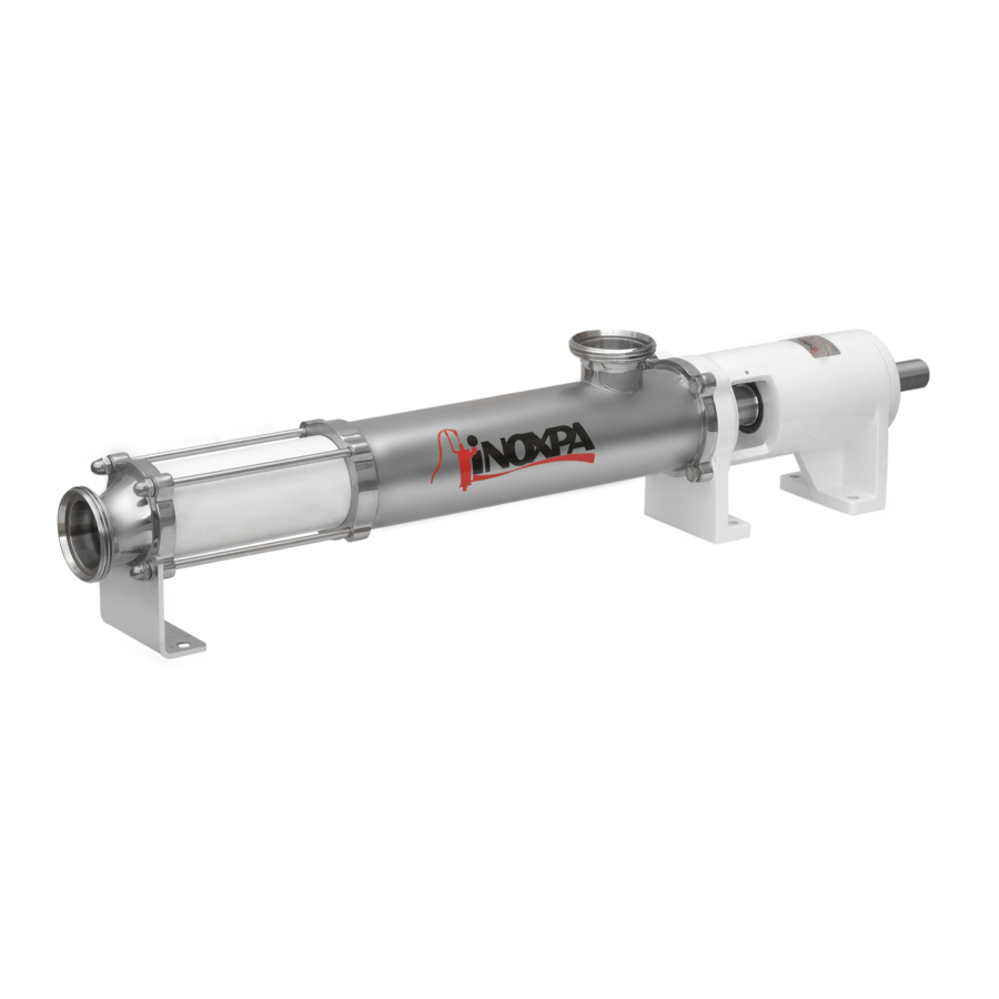
4. General Information 4.1. DESCRIPTION With a compact and robust design, INOXPA’s KIBER KS and KST progressive cavity pumps form part of our range of positive-displacement pumps with helical rotor, intended for viscous fluids. The hydraulic parts that form the pump are the rotor and the stator. The rotor is a round-section worm. The stator has two ribs and its pitch doubles that of the rotor, thus allowing empty cavities between the stator and the rotor. -
Page 7: Installation
Installation 5. Installation 5.1. RECEPTION OF THE PUMP INOXPA cannot be held responsible for the damage sustained by the equipment during transport or unpacking. Please visually check that the packaging is not damaged. The pump package includes the following documents: •... -
Page 8: Location
For the selection and fitting of the couplings, please refer to the supplier’s manual. In some cases, the starting torque of positive-displacement pumps can be quite high. Therefore, the chosen coupling should be 1,5 to 2 times the recommended torque. INOXPA S.A.U. · 01.610.30.11EN · (0) 2021/05... -
Page 9: Pipes
• Place the pump as close as possible to the suction tank and whenever possible below the liquid level, or even below the tank level in order to achieve the largest possible static head for suction. · INOXPA S.A.U. 01.610.30.11EN · (0) 2021/05... -
Page 10: Electrical Installation
Electrical equipment, terminals and components of the control systems may still carry current when they are disconnected. Contacting them may impose a hazard to operators or cause irreparable material damage. Before handling the pump, make sure that the motor is stopped. INOXPA S.A.U. · 01.610.30.11EN · (0) 2021/05... - Page 11 ALWAYS check the direction of rotation of the motor with liquid inside the pump. For models with a sealed chamber, ALWAYS make sure that the chamber is full of fluid before checking the direction of rotation. · INOXPA S.A.U. 01.610.30.11EN · (0) 2021/05...
-
Page 12: Start-Up
Before starting the pump, carefully read the instructions in section Installation. Carefully read section 9. Technical Specifications. INOXPA will not be liable for improper use of the equipment. NEVER touch the pump or the lines if hot liquids are being pumped. 6.1. CHECKS BEFORE STARTING THE PUMP •... - Page 13 Start-up The pump always leaves INOXPA with a by-pass mounted to work with the aspiration in the pump casing and the impulsion ahead. If the pump has not an incorporated a pressure by-pass you should mount a relief valve or any other device that limits the pressure to 7 bar for single-stage stator or 14 for double-stage stator pump.
-
Page 14: Troubleshooting
The following table provides solutions to problems that might arise during the operation of the pump. The pump is assumed to have been properly installed and be suitable for the relevant application. Please contact INOXPA if technical assistance is required. Motor overload... -
Page 15: Maintenance
8.6. CLEANING The use of aggressive cleaning products such as caustic soda and nitric acid may give raise to skin burns. Use rubber gloves during cleaning procedures. Always use protective goggles. · INOXPA S.A.U. 01.610.30.11EN · (0) 2021/05... - Page 16 Maximum conditions during SIP process with steam or overheated water: a) Maximum temperature: 140°C / 284°F b) Maximum time: 30 min c) Cooling: sterile air or inert gas d) Materials: EPDM (recommended) FPM/NBR (use with caution) INOXPA S.A.U. · 01.610.30.11EN · (0) 2021/05...
-
Page 17: Dissasembly And Assembly Of The Pump
Incorrect assembly or disassembly may cause damage to the pump’s operation and lead to high repair costs and a long period of downtime. INOXPA is not responsible for accidents or damages caused by a failure to comply with the instructions in this manual. - Page 18 • Introduce the stator (22) lubricating it with soapy water and if necessary secure the rotor (21) by holding the pump shaft (05). • Mount the discharge flange (34) and the leg (07) and fasten it with the nuts (54). INOXPA S.A.U. · 01.610.30.11EN · (0) 2021/05...
- Page 19 • Place the seal ring (31) on the shaft and fasten it with the pins (55) according to the following assembly dimension: Pump type A (mm) KS – 20 KS – 25/30 16,5 KS – 40/50 KS – 60/80 23,5 · INOXPA S.A.U. 01.610.30.11EN · (0) 2021/05...
- Page 20 • Place the seal ring (31) on the shaft and fasten it with the pins (55) according to the A dimension shown in the following figure: Pump type A (mm) KS – 20 12,0 KS – 25/30 16,5 KS – 40/50 23,0 KS – 60/80 23,5 INOXPA S.A.U. · 01.610.30.11EN · (0) 2021/05...
- Page 21 • Mount the cover (10) to the support of the bearing (06) having previously laced the O-rings (80,80B), and fasten it with the back cover of the double seal (10A) using the pins (55A) across the nuts (54A). · INOXPA S.A.U. 01.610.30.11EN · (0) 2021/05...
- Page 22 • Remove the ball bearing (70A), the spacer bushing (17) and the inner ring of the roller bearing (70). • Finally, remove the outer ring together with the bearing rollers (70) which will have remained housed into the support of the bearing (06). INOXPA S.A.U. · 01.610.30.11EN · (0) 2021/05...
- Page 23 • Mount the shaft-bearings assembly into the support of the bearing (06). • Place the seal (88). • Mount the bearings cover (12) with the seal (88A) inside it using the allen screws (51). · INOXPA S.A.U. 01.610.30.11EN · (0) 2021/05...
-
Page 24: Technical Specifications
Feeder screw (KIBER KST pump) 1.4301 (AISI 304) Other stainless steel parts 1.4301 (AISI 304) Seals in contact with the product Other materials for the seal consult with INOXPA External surface finish matt polished Ra ≤ 0,8 µm Internal surface finish Mechanical seal... -
Page 25: Particle Size
(Kg) type (Kg) type (Kg) KS-20 2KS-20 KST-20 2KST-20 KS-25 2KS-25 KST-25 2KST-25 KS-30 2KS-30 KST-30 2KST-30 KS-40 2KS-40 KST-40 2KST-40 KS-50 2KS-50 KST-50 2KST-50 KS-60 2KS-60 KST-60 2KST-60 KS-80 2KS-80 KST-80 2KST-80 · INOXPA S.A.U. 01.610.30.11EN · (0) 2021/05... -
Page 26: Dimensions Of Kiber Ks Pump
Pump type KS-20 2KS-20 KS-25 2KS-25 KS-30 2KS-30 1090 KS-40 1275 2KS-40 1160 KS-50 1415 2KS-50 1405 KS-60 1705 2KS-60 1535 KS-80 1935 2KS-80 9.4. DIMENSIONS OF KIBER KS PUMP WITH BY-PASS PRESSURE INOXPA S.A.U. · 01.610.30.11EN · (0) 2021/05... -
Page 27: Dimensions Of Kiber Kst Pump
9.5. DIMENSIONS OF KIBER KST PUMP Pump type KST-20 2KST-20 KST-25 1035 2KST-25 1125 KST-30 1035 2KST-30 1185 KST-40 1300 2KST-40 1490 KST-50 1375 2KST-50 1630 KST-60 1735 2KST-60 2035 KST-80 1865 2KST-80 2265 · INOXPA S.A.U. 01.610.30.11EN · (0) 2021/05... -
Page 28: Exploded Drawing And Parts List Of Kiber Ks Pump
Technical Specifications 9.6. EXPLODED DRAWING AND PARTS LIST OF KIBER KS PUMP INOXPA S.A.U. · 01.610.30.11EN · (0) 2021/05... - Page 29 Roller bearing Steel Ball bearing Steel O-ring Lip seal Lip seal recommended spare parts 6 units in the models KIBER KS-60, KIBER 2KS-60, KIBER KS-80, KIBER 2KS-80 pieces include in the transmission kit · INOXPA S.A.U. 01.610.30.11EN · (0) 2021/05...
-
Page 30: Exploded Drawing And Parts List Of Kiber Kst Pump
Technical Specifications 9.7. EXPLODED DRAWING AND PARTS LIST OF KIBER KST PUMP INOXPA S.A.U. · 01.610.30.11EN · (0) 2021/05... - Page 31 Roller bearing Steel Ball bearing Steel O-ring Lip seal Lip seal recommended spare parts 6 units in the models KIBER KST-60, KIBER 2KST-60, KIBER KST-80, KIBER 2KST-80 pieces include in the transmission kit · INOXPA S.A.U. 01.610.30.11EN · (0) 2021/05...
-
Page 32: Heavy Duty Transmission
Transmission shield bushing 1.4404 (AISI 316L) Rotor 1.4404 (AISI 316L) Connecting rod 1.4404 (AISI 316L) Bolt 1.4404 (AISI 316L) Safe ring 1.4404 (AISI 316L) Transmission bushing 1.4404 (AISI 316L) O-ring O-ring recommended spare parts INOXPA S.A.U. · 01.610.30.11EN · (0) 2021/05... -
Page 33: Cooled Mechanical Seal
Technical Specifications 9.9. COOLED MECHANICAL SEAL Position Description Quantity Material Cooled seal cover 1.4404 (AISI 316L) Lip seal Racord 1.4404 (AISI 316L) recommended spare parts · INOXPA S.A.U. 01.610.30.11EN · (0) 2021/05... -
Page 34: Double Mechanical Seal
Inside mechanical seal Outside mechanical seal Double seal cover 1.4404 (AISI 316L) Double seal back cover 1.4404 (AISI 316L) Hexagonal nut Threaded rod O-ring Racord BSPT 1.4401 (AISI 316) recommended spare parts INOXPA S.A.U. · 01.610.30.11EN · (0) 2021/05... -
Page 35: Gland Packing
Technical Specifications 9.11. GLAND PACKING Position Description Quantity Material Gland packing 5 rings Packing box 1.4404 (AISI 316L) Gland 1.4404 (AISI 316L) Self-locking nut · INOXPA S.A.U. 01.610.30.11EN · (0) 2021/05... - Page 36 How to contact INOXPA S.A.U.: Contact details for all countries are Continually updated on our website. Please visit www.inoxpa.com to access the information. INOXPA S.A.U. Telers, 60 – 17820 – Banyoles – Spain Tel.: +34 972 575 200 – Fax.: +34 972 575 502...
Need help?
Do you have a question about the KIBER KS Series and is the answer not in the manual?
Questions and answers