Table of Contents
Advertisement
Quick Links
Advertisement
Table of Contents

Related Manuals for INOXPA SLR-A


Summary of Contents for INOXPA SLR-A
- Page 1 INSTALLATION, SERVICE AND MAINTENANCE INSTRUCTIONS SLR-A INOXPA, S.A. c/Telers, 54 Aptdo. 174 E-17820 Banyoles - Girona (Spain) Tel.: (34) 972 - 57 52 00 Fax.: (34) 972 - 57 55 02 Email: inoxpa@inoxpa.com www.inoxpa.com Original Manual 01.505.30.00EN (B) 2021/11...
-
Page 4: Safety
SLR-A pump. The information published in the instruction manual is based on updated information. INOXPA reserves the right to modify this instruction manual without prior notice. 1.2. INSTRUCTIONS FOR START-UP This instruction manual contains essential and useful information for properly starting the pump and maintaining it in good operating condition. - Page 5 Modifications have been carried out of our products without our prior written authorization; • The parts or lubricating agents used are not original INOXPA parts/lubricants; • The material has been improperly used due to errors or negligence or it has not been used according to the indications and for the desired purpose.
-
Page 6: Table Of Contents
7.7. Assembly / disassembly of the mechanical seal option ................23 Technical Specifications ......................24 8.1. Technical specifications ......................... 24 8.2. Weights ..............................24 8.3. Options ..............................24 8.4. SLR-A dimensions ..........................25 8.5. Rectangular port dimensions ......................... 25 8.6. SLR-A parts breakdown ......................... 26 2.Table of contents 2021/11... -
Page 7: General Information
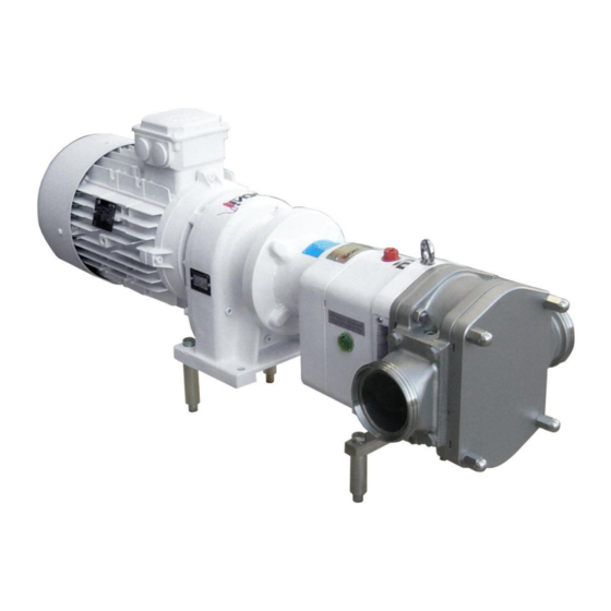
INOXPA's SLR-A lobe pumps are part of our wide range of positive displacement rotary pumps for viscous liquids. Thanks to the wider lobes installed in the SLR-A pump, it has a greater flow, appropriate for pressures of up to 6 bar. - Page 8 The field of application for each type of pump is limited. Each pump is ordered to meet specific pumping conditions. INOXPA will not be liable for any damage that may occur if the information provided by the buyer is incomplete (specifications of the liquid, RPM, etc.).
-
Page 9: Installation
Name plate on the pump 4.2. TRANSPORT AND STORAGE The SLR-A pumps are usually too heavy to be stored manually. Use an adequate means of transport. Use the points indicated in the diagram for lifting the pump. The pump should only be transported by authorized personnel. -
Page 10: Location
4.3. LOCATION • Place the pump as close as possible to the suction tank and if possible, below the liquid level. • Place the pump in a position that allows enough space around it to provide access to the pump as well as to the motor. (Refer to Technical specification Chapter 8 to verify the dimensions and weights). -
Page 11: Electrical Installation
4.5. ELECTRICAL INSTALLATION Only allow qualified personnel to connect the electrical motors. Take the necessary steps to prevent any failure of connections and cables. The electrical equipment as well as the terminals and control system components may remain electrically charged even when they are disconnected. Contacting them may impose a hazard to operators or cause irreparable material damage. -
Page 12: Start-Up
5.1. START-UP Technical specifications. Carefully read Chapter 8 INOXPA will not be liable if the equipment is improperly used. Do not touch the pump or the pipework while high temperature products are being pumped. 5.1.1. Inspections that must be carried out prior to starting the pump •... -
Page 13: Safety Valve
5.2. Safety valve The opening pressure adjustment of the safety valve is carried out at the INOXPA workshops. However, the pressure at which the valve opens depends on the fluid to be pumped, the viscosity, the rpm, etc., which means that prior to starting the pump, the user must set the opening pressure of the safety valve. -
Page 14: Operating Problems
The following table provides solutions to problems that may appear during normal pumping operations. It is hereby assumed that the pump has been installed properly and it has been properly selected for the pertinent application. Contact INOXPA if technical assistance is required. Operating problem Probable causes Motor overload. -
Page 15: Maintenance
Stop the pump for a moment and then re-check the oil level; if required, add a little oil. • The oil capacity of the SLR-A pump is 1.5 litres. • Oils for temperatures between 5 and 50ºC: SAE 90 or ISO VG 220. -
Page 16: Cleaning
7.3. CLEANING 7.3.1. Manual cleaning The use of aggressive cleaning products such as caustic soda and nitric acid can burn the skin. Use rubber gloves during the cleaning process. Always use protective goggles. 7.3.2. Automatic CIP (cleaning-in-place) If the pump is installed in a system with CIP, dismantling of the pump is not required. The minimum recommended liquid speed for an effective cleaning process is 1.8 m/s (minimum Reynolds number >... -
Page 17: Disassembly Of The Pump
Improper assembling or disassembling may cause damage that may affect the operation of the pump and result in high repair costs as well as a long period of inactivity. INOXPA will not be liable for accidents or damage caused by non-compliance with the instructions included in this manual. - Page 18 7.4.3. Disassembly of curved wear plates • Loosen the flange screws (51A). • Remove the curved wear plates (13C). 7.4.4. Disassembly of the body • Loosen and remove the nuts (54A) that fasten the body to the bearing support (06) •...
- Page 19 7.4.7. Draining the lubrication oil • Place a container below the bearing support (06) to collect the lubricating oil for its disposal. • Remove the drain cap (87) that is located on the rear side of the bearing support (06). •...
-
Page 20: Assembly Of The Pump
7.5. ASSEMBLY OF THE PUMP 7.5.1. Assembly of the shaft assembly • Check that the bearing cover gasket (18) is not damaged and mount it in the proper position on the bearing cover (12). • Place the bearings cover (12) and fasten with screws (52E). •... - Page 21 7.5.5. Assembly of the body CAUTION! When re-assembling the pump body, make a note of the position of the centring pins. • Slide the sleeve (13) over the shaft and place the O-ring (80D) on the sleeve. • Place the seal cover (09) along with the O-rings (80A) and the rear wear plate (32B).
-
Page 22: Setting And Synchronizing The Lobes
7.6. SETTING AND SYNCHRONIZING THE LOBES 7.6.1. Play and tolerances 7.6.2. Synchronizing the lobes • In order to allow the lobes to be synchronized, the bearing cover assembly and the pump cover assembly must be removed, the lobes (02) must be installed on the shafts and fastened with the screws (25). -
Page 23: Assembly / Disassembly Of The Mechanical Seal Option
Clean all the mechanical seal components prior to installing them. • Check that the working surfaces are not damaged. INOXPA recommends replacing all of the mechanical seals if one of the working surfaces is found to have some defect. •... -
Page 24: Technical Specifications
Maximum torque of the pump support ..............400 Nm The maximum allowed viscosity will depend on the type of liquid and the sliding speed of the seal sides. If the viscosity is higher, consult with INOXPA. Materials Parts in contact with the product ................ -
Page 25: Slr-A Dimensions
8.4. SLR-A DIMENSIONS Power TYPE [kW] SLR-A 1030 8.5. RECTANGULAR PORT DIMENSIONS 2021/11 8.Technical Specifications... -
Page 26: Slr-A Parts Breakdown
8.6. SLR-A PARTS BREAKDOWN 8.6.1. Breakdown of the pump 8.Technical Specifications 2021/11... - Page 27 8.6.2. List of parts Pos. Description Quantity Material Body CF 3M Wedge lobe AISI 431 Pump cover AISI 304 Drive shaft AISI 329 Driven shaft AISI 329 Support GG 25 Foot AISI 304 Adjustable foot AISI 304 Foot AISI 304 Gearbox foot AISI 304 Lip seal...
- Page 28 Tel: 38 050 720 8692 e-mail: kiev@inoxpa.com Fax: 33 467 568 745 e-mail: frigail.fr@inoxpa.com npourtaud@inoxpa.com npourtaud.fr@inoxpa.com In addition to our branches, INOXPA has a network of independent distributors in over 50 countries worldwide. For further information, visit our website. www.inoxpa.com...
Need help?
Do you have a question about the SLR-A and is the answer not in the manual?
Questions and answers