Table of Contents
Advertisement
Quick Links
Advertisement
Table of Contents

Related Manuals for INOXPA SLRT 3-90


Summary of Contents for INOXPA SLRT 3-90
- Page 1 INSTALLATION, SERVICE AND MAINTENANCE INSTRUCTIONS SLR-T INOXPA, S.A. c/Telers, 54 Aptdo. 174 E-17820 Banyoles Girona (Spain) Tel.: (34) 972 - 57 52 00 Fax. : (34) 972 - 57 55 02 Email: inoxpa@inoxpa.com www.inoxpa.com Original Manual 01.506.30.0001EN 2021/11...
-
Page 4: Safety
The use of safety goggles is mandatory ensured at all times 1.4. GENERAL SAFETY INSTRUCTIONS Read this instruction manual carefully before installing and starting the pump. Contact INOXPA if you have any doubts or queries. 1.4.1. During the installation Technical Specifications in Chapter 8 must always be observed. - Page 5 The environmental conditions in the room may impose a hazard due to the substances being released. 1.4.5. Warranty We wish to emphasise that any warranty will be void immediately and lawfully; INOXPA shall be compensated for any civil liability claims submitted by third parties in the following cases: •...
-
Page 6: Table Of Contents
2. Table of contents Safety 1.1. Instruction manual ......................4 1.2. Instructions for start-up ....................4 1.3. Safety .......................... 4 1.4. General safety instructions ..................... 4 Table of contents General information 3.1. Description ........................7 3.2. Principle of operation ..................... 7 3.3. -
Page 7: General Information
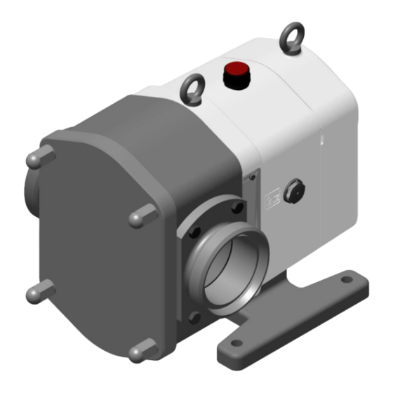
3.1. DESCRIPTION INOXPA's SLR-T lobe rotor pumps are part of our extensive range of positive displacement rotary pumps for viscous liquids. Thanks to the wider lobes of the SLR-T pump, it delivers a higher flow rate, appropriate for pressures of up to 7 bar. -
Page 8: Installation
4. Installation 4.1. RECEPTION OF THE PUMP INOXPA is not liable for any deterioration of the material caused by its transport or unpacking. Visually check that the packaging has not been damaged. The following documentation is included with the pump: •... -
Page 9: Location
Once the grout has hardened completely, the pump unit can be installed on the baseplate or frame. Carefully tighten the nuts on the foundation bolts. For other types of foundations, consult INOXPA. 4.4. COUPLING For selecting and installing couplings, please consult the supplier manual. On occasions, the starting torque of a positive displacement pump can be quite high. -
Page 10: Pipes
4.5. PIPEWORK • In general, suction and discharge pipes must be installed in straight sections, with the minimum number of elbows and fittings, in order to reduce wherever possible any pressure losses that may be caused by friction. • Make sure that the pump’s ports are properly aligned with the pipework and have a diameter similar to that of the pipe connections. -
Page 11: Auxiliary Line
4.6. AUXILIARY LINE 4.6.1. Heating/cooling jackets The heating/cooling jacket (S) is located at the front of the pump cover. There is also an option to fit a jacket in the area of the mechanical seal. Heating or cooling media can be connected as shown in the figure below. 4.7. -
Page 12: Electrical Installation
4.8. ELECTRICAL INSTALLATION Only allow qualified personnel to connect the electric motors. Take the necessary precautions to prevent damage to cables and connections. The electrical equipment as well as the terminals and control system components can remain electrically charged even when they are disconnected. Touching them may be dangerous for operators or cause irreversible damage to equipment. -
Page 13: Starting The Pump
5.1. STARTING THE PUMP Technical specifications. Carefully read Chapter 8 INOXPA is not liable for inappropriate use of the equipment. Do not touch the pump or the pipework while hot products are being pumped. 5.1.1. Inspections that must be carried out prior to starting the pump •... -
Page 14: Pressure Bypass
When checking the safety valve, make sure that the pump pressure NEVER exceeds the set pressure +2 bar. If the safety valve is not working properly, the pump must be put out of service immediately. The valve must be checked by INOXPA's technical service personnel. 5.Starting the pump 2021/11... -
Page 15: Operating Problems
The following table provides solutions to problems that may appear during normal pumping operations. It is assumed that the pump has been installed properly and that it has been correctly selected for the relevant application. Please contact INOXPA if you require technical assistance. Operating problems... -
Page 16: Maintenance
7. Maintenance 7.1. GENERAL CONSIDERATIONS Just like any other machine, this pump requires maintenance. The instructions in this manual cover the identification and replacement of spare parts. These instructions have been prepared by the maintenance personnel and are aimed at those responsible for the supply of spare parts. -
Page 17: Cleaning
7.3. CLEANING 7.3.1. Manual cleaning The use of aggressive cleaning products such as caustic soda and nitric acid can burn the skin. Use rubber gloves during the cleaning process. Always wear protective goggles. 7.3.2. Automatic CIP (Cleaning In Place) If the pump is installed in a system with CIP, dismantling of the pump is not required. The minimum recommended liquid speed for an effective cleaning process is 1.8 m/s (minimum Reynolds number >... -
Page 18: Disassembly Of The Pump
Incorrect assembly or disassembly may cause the pump to malfunction and lead to high repair costs and a long down-time period. INOXPA will not be liable for accidents or damage caused by failure to observe the instructions contained in this manual. - Page 19 INOXPA). • These screws have a right-hand thread. To prevent the lobes from turning simultaneously, the extraction tool handle can be used (this tool can be ordered from INOXPA). • Check that the O-rings (80) are in good condition. •...
-
Page 20: Assembly Of The Pump
7.4.5. Draining the lubricating oil • Place a container under the pump feet (07) to collect the lubricating oil so that it can be recycled. • Remove the drain plug (87) located on the rear side of the pump feet (07). - Page 21 INOXPA). • To prevent the lobes from turning simultaneously, the extraction tool handle can be used (this tool can be ordered from INOXPA). 7.5.6. Mounting the cover • Check that the seal (80A) is in good condition or replace it with a new one, if necessary.
-
Page 22: Disassembly / Assembly Of The Mechanical Seal
• Clean all components of the mechanical seal before installing them. • Check that the working surfaces are not damaged. INOXPA recommends replacing the entire mechanical seal if one of the working surfaces is found to have a defect. •... - Page 23 7.7.2. Synchronising the lobes • To be able to synchronise the lobes, it is first necessary to remove the pump body, the lobes, the seal cover and the seals as indicated in the corresponding sections. • Drain the oil from the bearing support, by removing the oil cap (85) and the drain plug (87).
-
Page 24: Technical Specifications
Pump weight ............................. The maximum permitted viscosity will depend on the type of liquid and the sliding speed of the seal sides. For higher viscosities, please consult with INOXPA. Materials Parts in contact with the product ................AISI 316L /329 Other stainless steel parts .................. -
Page 25: Noise Level
8.2. NOISE LEVEL The measurements were taken in accordance with EN 12639 / ISO 3746 - Grade 3. Tolerance ± 3dB. LpA in dB refers to the sound pressure level measured at a distance of 1 m from the surface of the machine and at a height of 1.6 m from the ground. -
Page 26: Slr-T Parts Breakdown
8.3. SLR-T PARTS BREAKDOWN 8.Technical Specifications 2021/11... -
Page 27: Slr-T Parts List
8.4. SLR-T PARTS LIST Item Description Quantity Material Body CF 3M Twin lobe impeller AISI 316L Cover AISI 316L Drive shaft AISI 329 Driven shaft AISI 329 Support GG 25 Foot GG 25 Rotating part of the seal Sil./EPDM Stationary part of the seal Graph./EPDM Seal cover AISI 316L... -
Page 28: Pump Safety Valve
8.5. PUMP SAFETY VALVE Item Quantity Description Material Safety valve body AISI 304 Pump cover for safety valve AISI 316L Spring bushing AISI 304 Piston AISI 316L Shaft - bolt AISI 304 Guide ring PTFE Adjustment nut AISI 304 Hex screw Hex nut Pivot AISI 304... -
Page 29: Front Heating Jacket
8.6. FRONT HEATING JACKET Item Quantity Description Material Pump cover heating jacket AISI 316L Front heating jacket AISI 304 Hex screw O-ring EPDM 8.7. REAR HEATING JACKET Item Quantity Description Material Rear heating jacket AISI 316 Heating jacket seal AISI 304 Allen screw Allen screw 2021/11... -
Page 30: Double Lip Seal
8.8. DOUBLE LIP SEAL Item Quantity Description Material Lip seals PTFE Seal cover AISI 316L Lip seal sleeve AISI 316L Stud O-ring EPDM 8.Technical Specifications 2021/11... - Page 31 NOTES...
- Page 32 Tel: 38 050 720 8692 e-mail: kiev@inoxpa.com Fax: 33 467 568 745 e-mail: frigail.fr@inoxpa.com npourtaud@inoxpa.com npourtaud.fr@inoxpa.com In addition to our branches, INOXPA has a network of independent distributors in over 50 countries worldwide. For further information, visit our website. www.inoxpa.com...
Need help?
Do you have a question about the SLRT 3-90 and is the answer not in the manual?
Questions and answers