Table of Contents
Advertisement
Quick Links
Advertisement
Table of Contents

Related Manuals for INOXPA HLR


Summary of Contents for INOXPA HLR
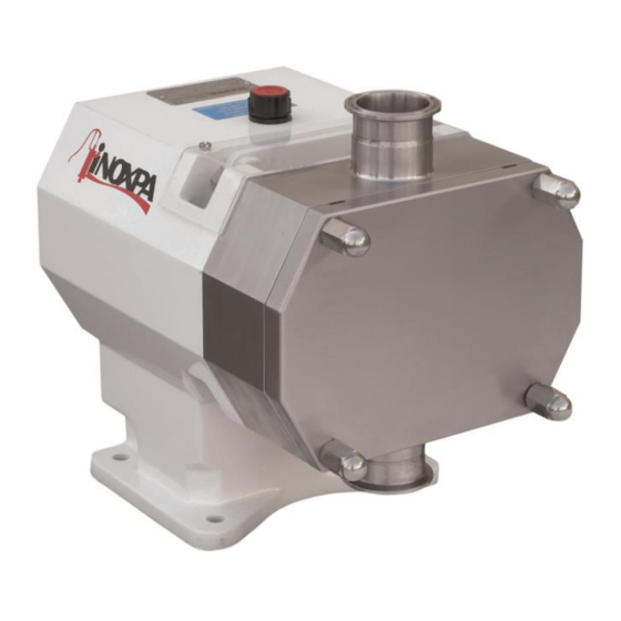
- Page 1 INSTALLATION, SERVICE AND MAINTENANCE INSTRUCTIONS Rotary Lobe Pump INOXPA, S.A. c/Telers, 54 Aptdo. 174 E-17820 Banyoles Girona (Spain) Tel. : (34) 972 - 57 52 00 Fax. : (34) 972 - 57 55 02 e-mail: inoxpa@inoxpa.com www.inoxpa.com Original Manual 01.504.30.00EN...
-
Page 4: Start-Up Instructions
HLR pump. The information given herein is based on the most up-to-date data available. INOXPA reserves the right to modify this instructions manual without having to give prior notice. 1.2. START-UP INSTRUCTIONS This instruction manual contains vital and useful information for properly operating the pump and for keeping it in good running condition. -
Page 5: During Maintenance
The use of other parts exempts the manufacturer from any and all responsibility. Any change in operating conditions can only be done with the prior written consent of INOXPA. In the event of doubt or should you require a fuller explanation on particular data (adjustment, assembly, disassembly...), please do not hesitate to contact us 1.Safety... - Page 6 7.7. Mechanical seal assembly and disassembly ..............26 Technical Specifications 8.1. Technical specifications ....................28 8.2. Weights ........................30 8.3. HLR dimensions ......................31 8.4. pump with flushing dimensions ..................33 8.5. HLR 0......................... 34 8.6. HLR 1......................... 36 8.7. HLR 2......................... 38 8.8.
-
Page 7: General Information
3.3. APPLICATION The main advantage of the INOXPA HLR rotary lobe pump is its capacity to pump a great variety of viscous liquids, from 1 mPa.s up to 100.000 mPa.s Furthermore, it is capable of pumping liquid products that require very careful handling and liquids that contain soft solids thus causing only a minimum degradation of same. - Page 8 The range of application for each type of pump is limited. The pump was selected for a given set of pumping conditions when the order was placed. INOXPA shall not be liable for any damage resulting from the incompleteness of the information provided by the purchaser (nature of the fluid, rpm, etc.).
-
Page 9: Installation
Serial number Pump plate 4.2. TRANSPORT AND STORAGE HLR pumps and pumping units are often too heavy to be handled manually. Use an adequate means of transport. Use the points which are indicated in the drawing for lifting the pump. - Page 10 • When the grout has entirely hardened the pump unit can be placed on the base plate or the frame. Tighten the nuts on the foundation bolts carefully. For other foundations consult INOXPA. 4.4. COUPLING For the couplings selection and assembly consult to the supplier manual. Sometimes the torque of the positive displacement pumps can be high enough.
-
Page 11: Shut-Off Valves
Maximum alignment deviations: Outside diameter of - Va the coupling [mm] [mm] [mm] [mm] [mm] 70 - 80 0,13 0,13 81 - 95 0,15 0,15 96 - 110 0,18 0,18 111 - 130 0,21 0,21 131 - 140 0,24 0,24 141 - 160 0,27 0,27... -
Page 12: Secondary Piping
If the seal requires flush media, the media supply and the purchase and installation of piping, valves ... for the media are not the responsibility of INOXPA. The flush shaft seal option is available on all seal types. Use the sectional drawings of the HLR seal options to purchase additional parts. -
Page 13: Pressure Relief Valve
4.7. PRESSURE RELIEF VALVE The positive displacement lobe pumps must be protected from excess pressure when they are operating. Consequently, all the HLR pumps can be fitted with a stainless steel pressure relief valve or a pressure by-pass 4.7.1. Protection This valve protects the pump and prevents excessively high pressure arising in the circuit. -
Page 14: Pressure By-Pass
The end user must adjust the valve to the correct pressure. When an overflow valve or a pressure bypass does not operate properly, the pump must immediately be removed from service for repair. The valve must be examined by the INOXPA technical assistance personnel. (A) 2021/11 5.Start-up... - Page 15 When checking the relief valve also make sure the pump's pressure will NEVER exceed the pressure setting + 2 bar. When the relief valve does not work properly, the pump must be taken out of service immediately. The valve must be inspected by an INOXPA service technician. 5.Start-up (A) 2021/11...
-
Page 16: Operating Problems
The table given below provides solutions to problems that might arise during pump operation. With respect to the same, it is assumed that the pump has been properly installed and has been correctly selected for the application in question. Should there be a need for technical service please contact INOXPA. Operating problems... -
Page 17: General Maintenance
Leave the pump switched off for a while and then re-check the oil level; if necessary, add a little oil. Oils for environment temperatures of 5 to 50ºC: SAE 90 or ISO VG 220 Quantity of oil in PUMP SIZE the gear case (l.) HLR 0 HLR 1 HLR 2 0,75 HLR 3... -
Page 18: Manual Cleaning
7.3. CLEANING 7.3.1. Manual cleaning The use of aggressive cleaning products such as caustic soda and nitric acid may give rise to skin burns. Use rubber gloves during the cleaning process. Always use protective goggles. 7.3.2. Automatic CIP (cleaning-in-place) If the pump is installed in a system fitted with a CIP process, there will be no need for stripping. The recommended minimum liquid speed for an effective process of cleaning is 1,8 m/s (minimum Re >... -
Page 19: Pump Disassembly
Incorrect assembly or disassembly may cause damage in the pump's operation and lead to high repair costs and a long period of down-time. INOXPA is not responsible for accidents or damages caused by a failure to comply with the instructions in this manual. - Page 20 • Place a container underneath the gear case (06) to collect the lubricant oil so that it can be recycled. • Remove the drainage plug (87) located to the rear of gear case. HLR 0 HLR 1,2,3,4 (A) 2021/11 7.Maintenance...
- Page 21 7.4.6. Shaft assembly removal Pumps Size 0: • Remove the key (61A) from the driveshaft (05). • Remove the screws (51C) and dismount the rear cover (12B) while checking that the O-ring (80E) does not stick to both sides. Pumps Size 1, 2, 3, 4: •...
-
Page 22: Pump Assembly
7.5. PUMP ASSEMBLY 7.5.1. Shaft assembly Pumps Size 0: • Check that the O-ring (80E) has not been damaged and attach it with a little grease or oil in the correct position of the bottom cover (12B). • Attach the rear cover and fix it on with screws (51C). •... - Page 23 Tighten the lobe screws (25) using a spanner. In order to prevent the lobes from turning simultaneously, blocks of wood or plastic can be placed between the lobes. • Assembly is exactly the same for all lobe types. HLR 1, 2, 3, 4 7.5.6. Pump cover assembly 7.Maintenance (A) 2021/11...
- Page 24 • Check that the O-ring (80A) is in good condition or, if applicable, replace it with a new one. • Place it in the pump rotor case (01) ensuring that no dirt or residue of any product remains in the seal or the rotor case. •...
- Page 25 7.6. LOBE ADJUSTMENT AND SYNCHRONISING 7.6.1. Clearance and tolerance table (mm) 0,12 0,07 0,15 0,15 0,35 HLR 0-20 ±0,05 ±0,03 ±0,05 ±0,05 ±0,05 0,15 0,08 0,15 HLR 0-25 ±0,05 ±0,03 ±0,05 ±0,05 ±0,05 0,15 0,15 0,15 0,35 HLR 1-25 ±0,05 ±0,05...
- Page 26 Pumps size 0-1 Pumps size 2 Pumps size 3-4 Pumps Size 0, 1, and 2: the adjustable fixing mechanism consists of three pieces: Allen screws (51A), bearing cones (65A), and impeller bushing (17B). Pumps Size 3 and 4: the adjustable fixing mechanism is a single piece (65). •...
-
Page 27: Mechanical Seal Assembly And Disassembly
• Clean all the components of the mechanical seal before placing them. • Check that the working surfaces are not damaged. INOXPA recommends replacing the entire mechanical seal if one of the working surfaces has a defect. • Replace the O-rings during assembly. - Page 28 • Clean all the components of the mechanical seal before placing them. • Check that the working surfaces are not damaged. INOXPA recommends replacing the entire mechanical seal if one of the working surfaces has a defect. • Replace the O-rings during assembly.
-
Page 29: Technical Specifications
The maximum viscosity allowed will depend on the nature of the liquid and the sliding speed of the seal faces. Consult INOXPA should the viscosity be still greater. Use special protection when the noise level in the operation area exceeds 85 dB(A). - Page 30 Materials Product wetted parts ............AISI 316L Other parts in stainless steel ..........AISI 304 Product wetted gaskets ............EPDM Other materials for optional gaskets ........Consult your supplier Product wetted parts surface finishing ........Ra < 0,8 m Mechanical seal Type of seal .................
- Page 31 < 2 % damage when using wing lobe geometry. Internal diameter Maximum theoretical Recommended maximum Pump size connection sphere frame theoretical sphere frame [mm] [mm] [mm] HLR 0-20 15,8 HLR 0-25 22,4 HLR 1-25 22,4 20,6 HLR 1-40 35,1 20,6 HLR 2-40...
- Page 32 8.3. HLR DIMENSIONS HLR 0 HLR 1, 2, 3 Pump size HLR 0-20 67,5 16,2 HLR 0-25 76,5 HLR 1-25 94,5 21,6 HLR 1-40 94,5 HLR 2-40 HLR 2-50 HLR 3-50 133,5 190 46,5 250 41,4 HLR 3-80 133,5 (A) 2021/11...
- Page 33 HLR 4 Pump size HLR 4-100 77,8 161,5 58,9 HLR 4-150 8.Technical Specifications (A) 2021/11...
- Page 34 8.4. HLR WITH COOLED MECHANICAL SEAL (QUENCH DIMENSIONS (1) Quench sealing connection 4 x G1/8" Pump size HLR 0-20 HLR 0-25 HLR 1-25 HLR 1-40 HLR 2-40 HLR 2-50 HLR 3-50 HLR 3-80 HLR 4-100 HLR 4-150 (A) 2021/11 8.Technical Specifications...
- Page 35 8.5. HLR 0 8.5.1. Exploded view 8.Technical Specifications (A) 2021/11...
-
Page 36: Spare Part List
8.5.2. Spare part list Pos. Description Quant. Material Rotor case AISI 316L HLR 0-20 ( short ) HLR 0-25 ( large ) Rotor AISI 316L HLR 0-20 ( short ) HLR 0-25 ( large ) Front cover AISI 316L Drive shaft... - Page 37 8.6. HLR 1 8.6.1. Exploded view 8.Technical Specifications (A) 2021/11...
-
Page 38: Spare Parts List
8.6.2. Spare parts list Pos. Description Quant. Material Rotor case AISI 316L HLR 1-25 ( short ) HLR 1-40 ( large ) Rotor AISI 316L HLR 1-25 ( short ) HLR 1-40 ( large ) Front cover AISI 316L Drive shaft... - Page 39 8.7. HLR 2 8.7.1. Exploded view 8.Technical Specifications (A) 2021/11...
- Page 40 8.7.2. Spare parts list Pos. Description Quant. Material Rotor case AISI 316L HLR 2-40 ( short ) HLR 2-50 ( large ) Rotor AISI 316L HLR 2-40 ( short ) HLR 2-50 ( large ) Front cover AISI 316L Drive shaft...
- Page 41 8.8. HLR 3 8.8.1. Exploded view 8.Technical Specifications (A) 2021/11...
- Page 42 8.8.2. Spare parts list Pos. Description Quant. Material Rotor case AISI 316L HLR 3-50 ( short ) HLR 3-80 ( large ) Rotor AISI 316L HLR 3-50 ( short ) HLR 3-80 ( large ) Front cover AISI 316L Drive shaft...
- Page 43 8.9. HLR 4 8.9.1. Exploded view 8.Technical Specifications (A) 2021/11...
- Page 44 8.9.2. Spare parts list Pos. Description Quant. Material Rotor case AISI 316L HLR 4-100 ( short ) HLR 4-150 ( large ) Rotor AISI 316L HLR 4-100 ( short ) HLR 4-150 ( large ) Front cover AISI 316L Drive shaft...
- Page 45 NOTES ____________________________________________________________________________________ ____________________________________________________________________________________ ____________________________________________________________________________________ ____________________________________________________________________________________ ____________________________________________________________________________________ ____________________________________________________________________________________ ____________________________________________________________________________________ ____________________________________________________________________________________ ____________________________________________________________________________________ ____________________________________________________________________________________ ____________________________________________________________________________________ ____________________________________________________________________________________ ____________________________________________________________________________________ ____________________________________________________________________________________ ____________________________________________________________________________________ ____________________________________________________________________________________ ____________________________________________________________________________________ ____________________________________________________________________________________ ____________________________________________________________________________________ ____________________________________________________________________________________ ____________________________________________________________________________________ ____________________________________________________________________________________ ____________________________________________________________________________________ ____________________________________________________________________________________ ____________________________________________________________________________________ ____________________________________________________________________________________ ____________________________________________________________________________________ ____________________________________________________________________________________...
- Page 46 NOTES ____________________________________________________________________________________ ____________________________________________________________________________________ ____________________________________________________________________________________ ____________________________________________________________________________________ ____________________________________________________________________________________ ____________________________________________________________________________________ ____________________________________________________________________________________ ____________________________________________________________________________________ ____________________________________________________________________________________ ____________________________________________________________________________________ ____________________________________________________________________________________ ____________________________________________________________________________________ ____________________________________________________________________________________ ____________________________________________________________________________________ ____________________________________________________________________________________ ____________________________________________________________________________________ ____________________________________________________________________________________ ____________________________________________________________________________________ ____________________________________________________________________________________ ____________________________________________________________________________________ ____________________________________________________________________________________ ____________________________________________________________________________________ ____________________________________________________________________________________ ____________________________________________________________________________________ ____________________________________________________________________________________ ____________________________________________________________________________________ ____________________________________________________________________________________ ____________________________________________________________________________________...
- Page 47 NOTES ____________________________________________________________________________________ ____________________________________________________________________________________ ____________________________________________________________________________________ ____________________________________________________________________________________ ____________________________________________________________________________________ ____________________________________________________________________________________ ____________________________________________________________________________________ ____________________________________________________________________________________ ____________________________________________________________________________________ ____________________________________________________________________________________ ____________________________________________________________________________________ ____________________________________________________________________________________ ____________________________________________________________________________________ ____________________________________________________________________________________ ____________________________________________________________________________________ ____________________________________________________________________________________ ____________________________________________________________________________________ ____________________________________________________________________________________ ____________________________________________________________________________________ ____________________________________________________________________________________ ____________________________________________________________________________________ ____________________________________________________________________________________ ____________________________________________________________________________________ ____________________________________________________________________________________ ____________________________________________________________________________________ ____________________________________________________________________________________ ____________________________________________________________________________________...
- Page 48 Tel: 33 320631000 Tel: 61 3 5976 8881 e-mail: inoxpa.fr@inoxpa.com Fax: 33 320631001 Fax: 61 3 5976 8882 e-mail: inoxpa.nord.fr@inoxpa.com e-mail: inoxpa.au@inoxpa.com INOXPA SOUTH AFRICA (PTY) LTD INOXPA USA, Inc INOXPA ALGERIE JOHANNESBURG SANTA ROSA ROUIBA Tel: 27 117 945 223...
Need help?
Do you have a question about the HLR and is the answer not in the manual?
Questions and answers