
Related Manuals for INOXPA PROLAC HCP SP Series


Summary of Contents for INOXPA PROLAC HCP SP Series
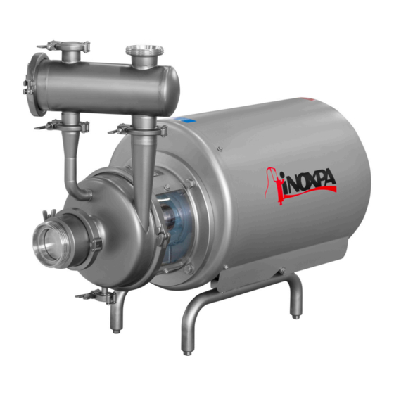
- Page 1 INSTALLATION, SERVICE AND MAINTENANCE INSTRUCTIONS SELF-PRIMING CENTRIFUGAL PUMP PROLAC HCP SP Original Instructions 01.031.30.03EN (A) 2022/01...
- Page 2 INOXPA S.A.U. Telers, 60 17820 - Banyoles (Spain) hereby declare under our sole responsibility that the SELF-PRIMING CENTRIFUGAL PUMP Machine: PROLAC HCP SP Model: PROLAC HCP SP 50-150 Type: PROLAC HCP SP 50-190 PROLAC HCP SP 65-215 IXXXXXXXXX IXXXXXXXXX Serial number:...
- Page 3 INOXPA S.A.U. Telers, 60 17820 - Banyoles (Spain) hereby declare under our sole responsibility that the SELF-PRIMING CENTRIFUGAL PUMP Machine: PROLAC HCP SP Model: PROLAC HCP SP 50-150 Type: PROLAC HCP SP 50-190 PROLAC HCP SP 65-215 IXXXXXXXXX IXXXXXXXXX Serial number:...
-
Page 4: Table Of Contents
1. Table of Contents 1. Table of Contents 2. Generalities 2.1. Instructions manual ..........................4 2.2. Compliance with the instructions ......................4 2.3. Warranty..............................4 3. Safety 3.1. Warning symbols............................. 5 3.2. General safety instructions ........................5 4. General Information 4.1. -
Page 5: Generalities
The non-compliance of the prescribed indications in this manual means misuse of this gear on the technical side and the personal safety and this, exempt INOXPA of all responsibility in case of accidents and personal injuries and/or property damage. Also, excluded from the warranty all breakdowns caused by improper use of the gear. -
Page 6: Safety
ATTENTION 3.2. GENERAL SAFETY INSTRUCTIONS Read the instruction manual carefully before installing and starting the pump. Contact INOXPA in case of doubt. 3.2.1. During installation Always take into account the Technical Specifications of chapter 9. Never start the pump before connecting it to the lines. - Page 7 ALWAYS disconnect the electrical power to the pumps prior to carrying out any mainte- nance. Remove the fuses and disconnect the cable from the motor’s terminals. All electrical work must be carried out by authorized personnel. INOXPA S.A.U. 01.031.30.03EN · (A) 2022/01...
-
Page 8: General Information
Misuse of the pump or its use beyond the operating limits may be dangerous or cause permanent damage to the equipment. INOXPA shall not be liable for any damage resulting from the incompleteness of the information provided by the purchaser (nature of the fluid, rpm, etc.). -
Page 9: Installation
Installation 5. Installation 5.1. RECEPTION OF THE PUMP INOXPA cannot be held responsible for the damage sustained by the equipment during transport or unpacking. Please visually check that the packaging is not damaged. The pump package includes the following documents:... -
Page 10: Transport And Storage
ATTENTION Install the pump so as to allow proper ventilation. If the pump is installed outdoors, it should be covered by a roof. Its location should allow easy access for inspection or maintenance operations. INOXPA S.A.U. 01.031.30.03EN · (A) 2022/01... -
Page 11: Adjustable Legs
ALWAYS connect the coolant inlet to the bottom connection on the seal chamber. The coolant will then exit through the top connection on the chamber. See the following figure. INOXPA S.A.U. 01.031.30.03EN · (A) 2022/01... -
Page 12: Electrical Installation
If the pump rotates in the wrong direction it could cause serious damage. ATTENTION See indicator label on the pump. ALWAYS check the direction of rotation of the motor with liquid inside the pump. INOXPA S.A.U. 01.031.30.03EN · (A) 2022/01... -
Page 13: Start-Up
Start-up 6. Start-up Before starting the pump, carefully read the instructions in section 5. Installation. Carefully read section 9. Technical Specifications. INOXPA will not be liable for impro- per use of the equipment. NEVER touch the pump or the lines of hot liquids are being pumped. 6.1. CHECKS BEFORE STARTING THE PUMP Before starting the pump:... -
Page 14: Checks When Starting The Pump
ATTENTION Control the motor consumption to prevent an electrical overload. To reduce the flow rate and the electrical power consumed by the motor: - reduce regulating the pump’s discharge flow, - decrease the motor speed. Use special protection when the sound pressure in the operation area exceeds 85 dB(A). INOXPA S.A.U. 01.031.30.03EN · (A) 2022/01... -
Page 15: Troubleshooting
The following table provides solutions to problems that might arise during the operation of the pump. The pump is assumed to have been properly installed and be suitable for the relevant application. Please contact INOXPA if technical assistance is required. Motor overload The pump does not provide enough flow or pressure... -
Page 16: Maintenance
The period between each preventive maintenance service will vary depending on the operating condition of the pump: temperatures, flow, number of operating hours, cleaning solutions used, etc. 8.4. TIGHTENING TORQUE Size lbf·ft 8.5. STORAGE Before being stored the pump must be completely emptied of liquids. Avoid, as far as possible, the exposure of the parts to excessively damp atmospheres. INOXPA S.A.U. 01.031.30.03EN · (A) 2022/01... -
Page 17: Cleaning
Maximum conditions during SIP process with steam or overheated water: a. maximum temperature: 140ºC / 284ºF b. maximum time: 30 min c. cooling sterile air or inert gas d. materials: EPDM (recommended) FPM (use with caution) INOXPA S.A.U. 01.031.30.03EN · (A) 2022/01... -
Page 18: Disassembly And Assembly Of The Pump
Incorrect assembly or disassembly may cause damage to the pump’s operation and lead to high repair costs and a long period of downtime. INOXPA is not responsible for accidents or damages caused by a failure to comply with the instructions in this manual. - Page 19 9. If the thrust washer and the seal spring need to be replaced, loosen the allen screws (51A) that secure the pump cover (03) and take it off. Then, loosen the allen screws (51) and remove the seal cover (09). 10. Check the spring and the thrust washer on the mechanical seal (08) and replace if necessary. INOXPA S.A.U. 01.031.30.03EN · (A) 2022/01...
- Page 20 4. Fit the spring on the thrust washer within the centring tabs. Place the thrust washer of the secondary seal on the spring. Make sure that the four tabs centring the spring are pointing inward. INOXPA S.A.U. 01.031.30.03EN · (A) 2022/01...
- Page 21 Apply it to the stationary parts on the cover as well as the rotating parts on the impeller and the double seal ring. 8.7.4. Installation and adjustment of the shaft Disassembly: 1. Loosen the allen screw (51D) of the retaining ring on the shaft (17). 2. Remove the shaft (05) together with the ring (17). Assembly: 1. Fit the pump shaft (05) together with the retaining ring (17) on the motor shaft. 2. Tighten the allen screw (51D) on the retaining ring slightly and check that the pump shaft (05) can still turn. Make sure to fit the retaining ring on the shaft (17) as shown in the figure. INOXPA S.A.U. 01.031.30.03EN · (A) 2022/01...
- Page 22 7. With the help of a thickness gauge, move the pump shaft so that the impeller is located at the required distance B from the pump casing (01): 0,4 mm for size pump 50-150 and 0,5 mm for the size pump 50-190 and 65-215. 8. Tighten the allen screw (51D) of the retaining ring (17) of the shaft. 9. Remove the pump casing (01), the impeller (02) and the cover (03) and continue with the assembly of the mechanical seal. INOXPA S.A.U. 01.031.30.03EN · (A) 2022/01...
-
Page 23: Technical Specifications
The measurements were carried out according to the standard EN 12639 / ISO 3746 Grade 3 with a tolerance of ±3 dB(A). Sound pressure LpA Sound power LwA Pump dB(A) dB(A) HCP SP 50-150 HCP SP 50-190 HCP SP 65-215 INOXPA S.A.U. 01.031.30.03EN · (A) 2022/01... -
Page 24: Dimensions And Weights
Technical Specifications 9.2. DIMENSIONS AND WEIGHTS Dimensions (mm) Weight Pump Motor (kg) HCP SP 50-150 HCP SP 50-190 HCP SP 65-215 1133 18,5 INOXPA S.A.U. 01.031.30.03EN · (A) 2022/01... -
Page 25: Technical Section And Parts List
1.4404 (AISI 316L) motor leg 1.4301 (AISI 304) adjustable leg 1.4301 (AISI 304) mechanical seal seal cover 1.4404 (AISI 316L) shroud 1.4301 (AISI 304) casing clamp 1.4301 (AISI 304) retaining ring 1.4301 (AISI 304) guide bushing 1.4404 (AISI 316L) impeller nut 1.4404 (AISI 316L) lantern protector PETP screw with washer allen screw INOXPA S.A.U. 01.031.30.03EN · (A) 2022/01... - Page 26 1.4404 (AISI 316L) seal clamp EPDM clamp 1.4301 (AISI 304) clamp blank cap 1.4404 (AISI 316L) clamp seal EPDM clamp 1.4301 (AISI 304) clamp 1.4301 (AISI 304) clamp seal EPDM clamp seal EPDM clamp blank cap 1.4404 (AISI 316L) clamp 1.4301 (AISI 304) clamp seal EPDM motor INOXPA S.A.U. 01.031.30.03EN · (A) 2022/01...
-
Page 27: Double Mechanical Seal
Technical Specifications 9.4. DOUBLE MECHANICAL SEAL Position Description Quantity Material double mechanical seal double seal cover 1.4404 (AISI 316L) double seal ring 1.4404 (AISI 316L) allen screw set screw O-ring EPDM O-ring EPDM straight connector 1/8’’ BSPT D.8 1.4401 (AISI 316) INOXPA S.A.U. 01.031.30.03EN · (A) 2022/01... - Page 28 How to contact INOXPA S.A.U.: Contact details for all countries are continually updated on our website Please visit www.inoxpa.com to acces the information. INOXPA S.A.U. Telers, 60 - 17820 - Banyoles - Spain...
Need help?
Do you have a question about the PROLAC HCP SP Series and is the answer not in the manual?
Questions and answers