Advertisement
LED DALI Controller Touch RGBW DT8 - 1 Zone (Group)
User Manual
1. Product Description
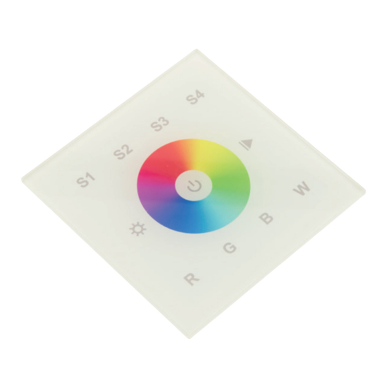
The DALI controller is a touch panel and sends DALI signals to DALI actors. This controller is
suitable for RGB and RGBW LED lights. It has a high sensitive glass touch panel with which you
can adjust any desired colour. The touch panel can control 1 DALI group and 4 DALI scenes.
The DALI Device Type (DT) 8 device can be supplied passive via DALI bus or activ supplied
with 230VAC. Mounting on a commercially available 68mm flush-mounted box.
2. Specifications
Power Supply
Operation current
DALI Bus Output
Output Signal
Max. wire-cross section
dimensions
3. Operation Manual
ON/OFF button
When switched on, a blue LED lights up above the colour wheel.
Brightness
Press and hold down to increase / decrease the light intensity.
Play/Pause button
First short keystroke: Starting the 8 permanently stored color gradients.
Repeated short press: Pause the color gradient.
Long press of the button: The color speed is increased or slowed down.
100-240VAC oder DALI Bus
230VAC: <15mA | DALI consumption: 4mA
max. 100mA
DALI
1,5mm²
86 x 86 x 41,6 mm
Item no.: LC-004-914
Advertisement
Table of Contents

Related Manuals for AUTLED LC-004-914


Summary of Contents for AUTLED LC-004-914
- Page 1 LED DALI Controller Touch RGBW DT8 - 1 Zone (Group) User Manual Item no.: LC-004-914 1. Product Description The DALI controller is a touch panel and sends DALI signals to DALI actors. This controller is suitable for RGB and RGBW LED lights. It has a high sensitive glass touch panel with which you can adjust any desired colour.
- Page 2 Colour wheel At the colour wheel you can choose the desired colour or the colour mix. scene buttons These keys can be used to recall and store moods. To save a scene, proceed as follows: Press a scene button for 3 seconds until the connected LED lights up, the set scene has now been saved.
- Page 3 If you set the rotary switch to position „0“ in Scene, the 4 possible scenes become (S1-S4) stored in the DALI actors under scene 0 to scene 3. If you set the rotary switch, e.g. at position „7“, scenes 7-10 are occupied and at position „F“ scenes 15, 0, 1 and 2 are occupied.
- Page 4 5. Installation 6. Wiring Diagram Passiv: Supply via external DALI bus power supply...
- Page 5 Active: Connection via 230VAC Active: If supply is with 230VAC, the touch panel provides a bus supply (100mA) to control 50 DALI actors. In broadcast mode, a maximum of 2 active panels and 2 passive panels for controlling 100 DALI actors can be connected to a DALI line.
Need help?
Do you have a question about the LC-004-914 and is the answer not in the manual?
Questions and answers