Advertisement
Quick Links
Advertisement

Related Manuals for TASKING i SYSTEM ARM


Summary of Contents for TASKING i SYSTEM ARM
- Page 1 ARM Galvanic Isolation Adapter V1.2 User Manual March 2023...
- Page 2 This document and all documents accompanying it are copyrighted by iSYSTEM AG and all rights are reserved. Duplication of these documents is allowed for personal use. In all other cases, written consent from iSYSTEM is required. iSYSTEM AG. All rights reserved. All trademarks are property of their respective owners.
-
Page 3: Table Of Contents
Contents ARM 20-pin 2.54mm Galvanic Isolation Adapter Package content ............................5 Specifications ............................6 Device overview ............................7 Connecting procedure .......................... 10 Accessories ............................. 11... -
Page 4: Arm 20-Pin 2.54Mm Galvanic Isolation Adapter
ARM 20-pin 2.54mm Galvanic Isolation Adapter Galvanic isolation is used where two electric circuits must communicate, but their grounds may be at different potentials. It is an effective method of breaking ground loops between the two circuits. Galvanic isolation is also used for safety, preventing accidental current from reaching ground through a person's body. -
Page 5: Package Content
Package content ARM 20-pin 2.54 mm Galvanic Isolation Adapter is delivered with the following components: ARM 20-pin 2.54 mm USB-C Power supply Ribbon cable Galvanic Isolation Adapter Ordering code: Ordering code: Ordering code: IEA-GI-ARM IT5V2AUSBC-PS IA20PIN20PIN254-10 User Manual... -
Page 6: Specifications
Specifications GENERAL Operating temperature 10°C to 40°C Storage temperature -10°C to 60°C MECHANICAL Size 65 x 40 x 19 mm Weight approx. 55 g ELECTRICAL Isolation Type Basic Isolation Ratings 1 kVrms VIORM * 560 V peak DEBUG TOOL SIDE Supply Voltage 5 V (via attached power supply) Max Supply Current... -
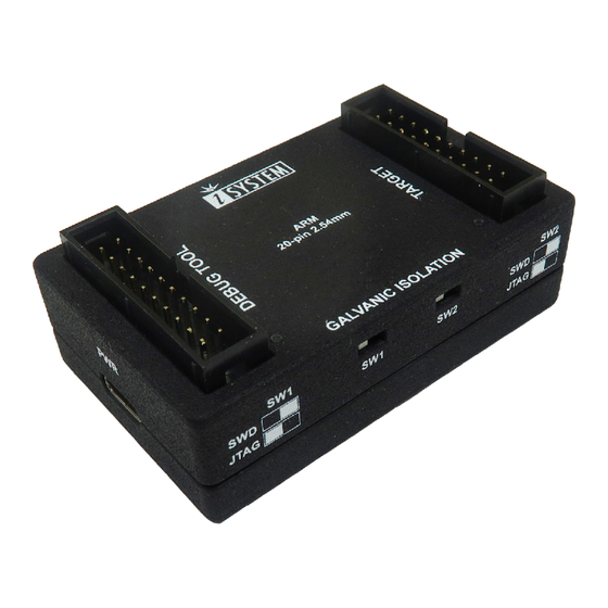
Page 7: Device Overview
Device overview The top face of the Galvanic Isolation Adapter features: A – DEBUG TOOL connector. B – TARGET connector. C – LED lights indicate power supply status. If LEDs on the GI Adapter are OFF, immediately turn everything OFF! The side face of the Galvanic Isolation Adapter features: D –... - Page 8 Both jumpers (SW1, SW2) should be in the same position to achieve the desired debug interface. The legend is printed on the housing. Debug interface JTAG...
- Page 9 Pinout The following pinout is valid on the target side: Signal Signal Signal Description Signal Signal Signal Description Direction Direction Reference Voltage Vref Not Connected JTAG nTRST Ground Not Connected / JTAG NC/TDI Ground I/O / O SWD/JTAG SWDIO/TMS Ground SWD/JTAG SWDCLK/TCK Ground...
-
Page 10: Connecting Procedure
Connecting procedure Do not use a Grounding wire between the BlueBox and the embedded target since it would counteract the primary functionality of the Galvanic Isolation (GI) Adapter! 1. Make sure you select a suitable debug interface (SWD, JTAG) via switches SW1 and SW2 on the GI Adapter. -
Page 11: Accessories
Accessories Ordering Code Description IC57000 iC5700 BlueBox IC57125-1 ARM HSSTP II Active Probe IC57125 ARM HSSTP Active Probe IC50111-1 20-pin 2.54 mm ARM Debug Adapter IASAM40ARMPIN20 Samtec40 to 20-pin JTAG ARM Converter Please refer to the iC5700 BlueBox User Manual for all current iC5700 Accessories. Find more information on www.isystem.com or contact sales@isystem.com. - Page 12 iSYSTEM has made every effort to ensure the accuracy and reliability of the information provided in this document at the time of publishing. Whilst iSYSTEM reserves the right to make changes to its products and/or the specifications detailed herein, it does not make any representations or commitments to update this document.
Need help?
Do you have a question about the i SYSTEM ARM and is the answer not in the manual?
Questions and answers