Table of Contents
Advertisement
Quick Links
Advertisement
Table of Contents

Related Manuals for Time Electronics 5030


Summary of Contents for Time Electronics 5030
- Page 1 User Manual 5030 Electrical Tester Calibrator Revision 2303-1 Time Electronics Ltd Unit 5, TON Business Park, 2-8 Morley Road, Tonbridge, Kent, TN9 1RA, United Kingdom. T: +44 (0) 1732 355993 | F: +44 (0) 1732 350198 mail@timeelectronics.co.uk | www.timeelectronics.com...
- Page 2 All rights reserved. Nothing from this manual may be multiplied, or made public in any form or manner, either electronically or hard copy, without prior written consent from Time Electronics Ltd. This also applies to any schematics, drawings and diagrams contained herein.
-
Page 3: Table Of Contents
Time Electronics 5030 Electrical Tester Calibrator User Manual Contents Introduction ............................ 4 Overview ..............................4 Specifications ............................5 Important Information ..........................7 Installation ............................. 8 Controls ............................10 Operation ............................11 Turning the unit On/Off ........................11 User Interface ............................12 Function Menu ............................. -
Page 4: Introduction
Applied Continuity test current and voltage. • In order for the 5030 to provide a true value of the selected Loop impedance, it can measure the supply local loop impedance. Front panel user interface is via a 4 line x 20 character LCD screen and user controls are simple and intuitive using 7 buttons. -
Page 5: Specifications
Time Electronics 5030 Electrical Tester Calibrator User Manual Specifications 1.2.1 Technical Specifications Loop Function Range / Values Resolution Accuracy Loop Impedance Resistor 1800, 330.0, 180.0, 33.00, 18.00, 3.300, 1.800, 4 digit ± 0.5 % of displayed value ± 30 mΩ... - Page 6 Dimensions / Weight ......W 430 x H 155 x D 255 mm / Weight: 8 kg. Supplied with ........User manual, RS-232 cable, USB adaptor/cable. 1.2.3 Ordering Information 5030 ............. Electrical Tester Calibrator C201 ............ Traceable calibration certificate (Factory) C137 ............ Accredited calibration certificate (ISO 17025) ECFLA ..........EasyCal Calibration Software...
-
Page 7: Important Information
Important Information Safety Warnings Observe all warnings before operating the 5030: The 5030 is a class I Instrument with a metal case connected to Supply Protective Earth. The supply Live and Neutral and Protective Earth wiring must be checked before connecting the 5030. -
Page 8: Installation
Positioning the Instrument Benchtop Use The 5030 should always be positioned on a flat, firm surface. The instrument base is fitted with four feet. The front feet have tilt legs to angle the instrument upwards for ergonomic front panel operation. - Page 9 The supply circuit may be protected by a RCD of 30 mA or greater rating as all test currents flow in the live – neutral circuit. The 5030 must only be connected via the heavy duty lead supplied with the instrument. Note that the plug on the mains lead will be as specified on order (regional type required).
-
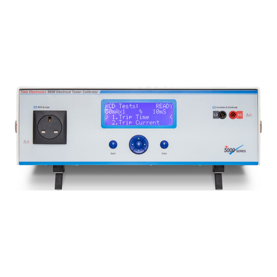
Page 10: Controls
4x20 LCD display Menu navigation and Insulation/Continuity Mains test socket BACK,OK, ENTER terminals buttons Note: The 5030 can be fitted with a number of regional type mains sockets. This must be specified on order. 5030 Electrical Tester Calibrator Page 10 of 43... -
Page 11: Operation
Time Electronics 5030 Electrical Tester Calibrator User Manual Operation Turning the unit On/Off To Turn On Turn the mains power switch at the rear panel of the instrument to ON (I). The front panel display show a startup screen with the software version for 3 seconds:... -
Page 12: User Interface
5030 Electrical Tester Calibrator User Manual User Interface The 5030 user interface is via menus on the front panel LCD display and navigation using the 7 push buttons. The buttons and their use are: Go back a level in the menu structure... -
Page 13: Function Menu
4. Insulation 5. Continuity 6. Setup When the 5030 is displaying the Function menu, the mains test socket is not live. Any UUT to be tested or calibrated can be connected safely, switched on and any setup required preparing for calibration. -
Page 14: Voltage Function
1. The UUT should be connected to the front panel mains test socket and ready to measure applied mains voltage. 2. The test status shows “READY” this indicates that the 5030 has is ready to perform a test. The user can start the test by pressing ENTER. Note the voltage function does not have any menu items to select. - Page 15 In Voltage, Loop and RCD functions when the front panel mains socket is energized the 5030 checks for excessive current flow from L (Live) to PE (Protective Earth). This is a typical failure mode for an Electrical Tester and is commonly caused by a short circuit in a control thyristor.
-
Page 16: Loop Function
User Manual Loop Function The 5030 can replicate loop impedances at a total of 10 test points for verification of both high and low current Loop Testers. The test point is made up of the sum of the mains supply local loop impedance and a loop test resistor within the 5030. - Page 17 Time Electronics 5030 Electrical Tester Calibrator User Manual To measure the supply local loop: 1. Select the Loop function from the function menu. 2. Press the ▼ button to select menu item 2. “Meas Loc Loop” Loop Tests: READY Loop function Test status: Ready 0.379 R...
- Page 18 4. On the UUT press the test button to start a loop measurement. Some Electrical Testers will auto-start measurement after detecting the mains voltage has been applied. 5. Compare the UUT measured Loop impedance (Zs) with the value displayed on 5030. The PSCC value is updated by measurements of the mains voltage once every second (1 Hz reading rate).
-
Page 19: Rcd Function
User Manual RCD Function The 5030 can simulate an RCD to allow verification and calibration of RCD testers via two modes, RCD Time mode and RCD Current mode. When performing RCD tests there are a number of test parameters that need to be set to match the UUT. - Page 20 6. The operator should now conduct the RCD test on the UUT. When the UUT applies a test trip current greater than the Threshold setting, the 5030 will trigger to simulate an RCD. The 5030 will indicate the test is finished by changing the test status and also indicate the detected phase of the trip current, either 0°...
- Page 21 Time Electronics 5030 Electrical Tester Calibrator User Manual 3.6.2 Measure the RCD trip current (RCD Current mode) Test status: Ready RCD Tests: READY RCD function to start test indication 30mAx1 Current > 1.Trip Time < RCD Current mode RCD trip current and 2.Trip Current...
- Page 22 Threshold setting, this will trigger the 5030 to start measurement of the applied current (after any delay setting). The 5030 will indicate the test is finished by changing the test status as well as indicating the measured current and detected phase of the trip current.
- Page 23 3.6.3 RCD Threshold setting The Threshold setting sets the minimum level of applied RCD trip current until the 5030 acknowledges a valid start of test. There are two settings for the threshold which correspond to the I Multiplier setting used in the test.
- Page 24 The delay setting sets a delay for RCD Current mode tests. The delay period starts when the RCD threshold is detected to when the 5030 should start trip current measurement. There are two settings for the delay which correspond to the I Multiplier setting used in the test.
-
Page 25: Continuity Function
< 2.Hi Range -/+ The 5030 can provide accurate resistance as well as measure the applied voltage and current to allow Continuity testers to be calibrated and verified. Continuity tests require the UUT to be connected to the 4mm Insulation/Continuity terminals on the front panel. - Page 26 Because of this it is possible for the resistance of each step to be different following a calibration adjustment of the 5030, as well as one 5030 displaying different values from another.
- Page 27 3.7.3 Current measurement (S/C Current) The 5030 can measure the current that the Continuity tester produces while providing a 1 or 2 Ohm load. 1. Move the menu cursor to highlight “3. S/C Current”. Press ◄ or ► to change the load setting from 1 R to 2 R.
-
Page 28: Insulation Function
< 2.Hi Range The 5030 can provide accurate resistance as well as measure applied voltage to allow Insulation testers to be calibrated and verified. Insulation tests require the UUT to be connected to the 4mm Insulation/Continuity terminals on the front panel. - Page 29 Note: It is possible to press ENTER during the value entry to store the value and enable the Insulation/Continuity terminals immediately. 5. Start the UUT on insulation resistance measurement across the terminals and compare the measured resistance with the setting on the 5030. 5030 Electrical Tester Calibrator Page 29 of 43...
- Page 30 Record the measured voltage on the 5030 display. The display reading is updated once a second (1 Hz reading rate). Note: The 5030 will only start measurement when the applied voltage is greater than 10% of the range.
-
Page 31: Setup
Time Electronics 5030 Electrical Tester Calibrator User Manual Setup The setup menu allows you to change the 5030 display contrast and enter calibration mode for adjustment of the 5030. 3.9.1 Adjust display contrast 1. Press ▲ and ▼ to move the menu cursor to highlight “1. Contrast -/+”. -
Page 32: Rcd Test Waveform Problems
RCD Testers do not often produce a clean test waveform. Pre-test low amplitude currents may be present as well as switching spikes. The 5030 allows both threshold and delay to be programmed separately for x.5 and x1,2,5 multiplier settings. See 3.6.3 – RCD Threshold setting and 3.6.4 – RCD Delay setting. -
Page 33: Sample Waveforms
Time Electronics 5030 Electrical Tester Calibrator User Manual Sample Waveforms The following screen shots show pre test waveforms which may be encountered. 4.2.1 BEHA Unitest 9061 The sine wave pre-test current is 40% of the x1 amplitude and begins 950mS before the test waveform. - Page 34 Time Electronics 5030 Electrical Tester Calibrator User Manual 4.2.2 ISO-TECH IRT2310 The pre-test pulse is a positive ¼ cycle current and is 50% of the x1 amplitude. The delay from this pulse to the test waveform is 180mS. A delay >200mS will be suitable for the x0.5 ranges.
- Page 35 Time Electronics 5030 Electrical Tester Calibrator User Manual 4.2.3 Megger 1552 5030 Electrical Tester Calibrator Page 35 of 43...
- Page 36 The third is a pre-test sequence of one cycle of 50% of the x1 amplitude followed by one cycle of zero amplitude, repeated 8 times. The first narrow spike will be filtered out by the 5030. A delay >1500mS will be suitable for the x0.5 ranges.
- Page 37 Time Electronics 5030 Electrical Tester Calibrator User Manual 4.2.5 Socket & See PDRC380 The pre-test pulse is 500uS wide and is 50% of the x1 amplitude. It can be positive or negative. The delay from this pulse to the test waveform is 15mS for the positive pulse, 25mS for negative pulse.
-
Page 38: Remote Control
5030 Electrical Tester Calibrator User Manual Remote Control The 5030 supports remote control via commands sent as RS-232 data through a 9 pin female D-type connector on the rear panel. The commands allow control of the selected function, function parameters, starting and stopping tests as well as readback of results. -
Page 39: Command List Reference
Time Electronics 5030 Electrical Tester Calibrator User Manual Command list reference 5.2.1 Function modes, readback and trigger Command Parameter Result FUNC "NONE","VOLT","LOOP", "LOCL" Selects a specific function. Can only be changed when no test is in progress. "RCDT","RCDC", "INSL", "INSH", "INSV", "CONL", "CONH", "CONI",... - Page 40 Time Electronics 5030 Electrical Tester Calibrator User Manual 5.2.2 Function parameters Command Parameter Result LVAL “0” to “9” Set loop value to step 0 to 9, corresponding to nominal loop values 0.05R to 1830R in loop tests MAMP “0” to “7”...
-
Page 41: Re-Calibration
Normally re-calibration is done at 12 month intervals. The 5030 calibration/service manual is supplied separately and available upon request from Time Electronics. It is recommended that if possible, the unit be returned to the Time Electronics factory for periodic service maintenance and calibration. 5030 Electrical Tester Calibrator... -
Page 42: Warranty And Servicing
Time Electronics’ total liability is limited to repair or replacement of the product. Note that if Time Electronics determine that the fault on a returned product has been caused by the user, we will contact the customer before proceeding with any repair. - Page 43 User Manual Returning Instruments Prior to returning your product please contact Time Electronics. We will issue a return merchandise authorization (RMA) number that is to accompany the goods returning. Further instructions will also be issued prior to shipment. When returning instruments, please ensure that they have been adequately packed, preferably in the original packing supplied.
Need help?
Do you have a question about the 5030 and is the answer not in the manual?
Questions and answers