Table of Contents
Advertisement
Quick Links
Advertisement
Table of Contents

Subscribe to Our Youtube Channel
Related Manuals for Time Electronics 1021


Summary of Contents for Time Electronics 1021
- Page 1 Time Electronics 1021 Current Source With Null Measuring Facility Technical Manual V1.4 14/12/10 Time Electronics Ltd Botany Industrial Estate, Tonbridge, Kent, TN9 1RH Tel: +44(0)1732 355993 Fax: +44(0)1732 770312 Email: mail@TimeElectronics.co.uk Web Site: www.TimeElectronics.com...
-
Page 2: Table Of Contents
Calibration Procedure ..................12 7.2. Linearity ......................13 G uarantee & S ervic ing ..................14 All Time Electronics' instruments are subject to continuous development and improvement and in consequence may incorporate minor detail changes from the information contained herein. 1021 Technical Manual... -
Page 3: Introduc Tion
20 ppm per hour at constant temperature. To improve the switch reliability, additional back- up contacts have been used – even if a contact fails, the 1021 will still operate correctly. The accuracy and stability are such that a wide range of applications are possible. In the process industries it may be used to test and calibrate current sensitive transducers, and their associated indicating and recording instruments. -
Page 4: Specifications
1.4kg including protective boot Optional Extras: Leather Carry Case (9027) Factory Calibration Certificate (9153) UKAS Calibration Certificate (9105) Additional Rechargeable Battery Packs: 230V mains charger and 8 NiMH cells (9529) 110V mains charger and 8 NiMH cells (9528) 1021 Technical Manual... -
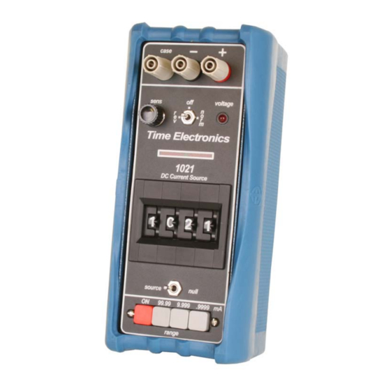
Page 5: C Ontrols
2. C ontrols 1021 Technical Manual... - Page 6 5. Voltage Limit Indicator An LED which indicates when the 1021 is unable to supply sufficient drive voltage to maintain the set output current, e.g. the maximum drive voltage of the instrument.
-
Page 7: Operation
3. Operation 3.1. Preliminaries The 1021 is supplied complete with rechargeable batteries (housed in the instrument) and a mains charger. Before operation, the batteries should be checked on the battery level indicator. It is important to recheck the battery condition when the instrument is supplying currents in excess of a few tens of mA, since the additional load may reduce the battery voltage to below the minimum level. -
Page 8: E Lec Tric Al Nois E P Ic K-Up
(several volts peak to peak) the output circuitry of the 1021 is overloaded by the noise signal and it converts it into a DC offset with results in an error in the output. -
Page 9: C Irc Uit Des C Ription
The standard recharger requires a mains input of 200V to 240V at 50/60Hz. A recharger requiring 100V to 120V at 50/60Hz is also available but should be specified when ordering. The recharger is connected to the 1021 by a miniature 2 pin plug and socket shaped to ensure correct polarity. -
Page 10: Maintenanc E And R Epair
Fuses are rated at F1A (F1), and F250mA (F2), and have dimensions 20mm length by 5mm diameter. The fuses are available from Time Electronics Ltd or your local supplier. 6.2. Repair NOTE: No repair work should be undertaken by the customer while the instrument is under warranty as such work may render the warranty invalid. -
Page 11: R Ec Alibration
The customer should also ensure that the correct equipment is available before attempting recalibration. There are 2 ways the 1021 can be recalibrated: The output current can be converted to a voltage by connecting a precision resistor across the output terminals. 3 values are required, 100, 1K and 10K ohms. The resistors must be accurate to better than 0.01% and have a good stability under load. -
Page 12: Calibration Procedure
(a) the 100 ohm precision resistor should be used. 4. Select the 100mA range and set all digits to 9999. Adjust the ‘100MACAL’ trimmer for exactly 100mA output. For recalibration method (a) the 10 ohm precision resistor should be used. 1021 Technical Manual... -
Page 13: Linearity
The linearity of the output is determined by specially matched resistors mounted on the rear of the digit switch. The matching is done when the 1021 is manufactured. Under normal operating conditions the high performance of these resistors ensures that the 1021 linearity will remain within specification for the instrument’s lifetime. -
Page 14: G Uarantee & S Ervic Ing
We maintain comprehensive after sales facilities and the unit can, if necessary be returned to us for servicing. During this period, Time Electronics Ltd will, at its discretion, repair or replace the defective items. For servicing under guarantee, the instrument type and serial number must always be quoted, together with details of any fault and the service required.
Need help?
Do you have a question about the 1021 and is the answer not in the manual?
Questions and answers