Table of Contents
Advertisement
Quick Links
Advertisement
Table of Contents

Related Manuals for Time Electronics 5041


Summary of Contents for Time Electronics 5041
- Page 1 5041 Oscilloscope & Timer Counter Calibrator Technical Manual Time Electronics Ltd Unit 11 Botany Industrial Estate Tonbridge, Kent, TN9 1RH Tel: 01732 355993 Fax: 01732 770312 E-Mail: mail@TimeElectronics.co.uk Web Site: www.TimeElectronics.co.uk V10.3 16/04/08...
-
Page 2: Table Of Contents
Page 2 CONTENTS Chapter 1 - INTRODUCTION ............3 Chapter 2 - SPECIFICATION ............4 Chapter 3 - SETUP & FRONT PANEL..........5 Mains Input Voltage Communication Settings Communication Connections GPIB User Commands Front Panel Output Connections Chapter 4 - OPERATION ..............9 Installing program on PC Amplitude Function Fast Rise Function (Bandwidth Determination) -
Page 3: Chapter 1 - Introduction
Chapter 1 - INTRODUCTION 5041 OSCILLOSCOPE & TIMER/COUNTER CALIBRATOR The 5041 is a versatile high accuracy calibrator capable of calibrating a wide range of oscilloscopes and timer/counters to 2.2GHz. It provides a wide range of calibrated outputs for amplitude, frequency, period and bandwidth. -
Page 4: Chapter 2 - Specification
PC Requirement PC running Windows 98, ME, 2000, or XP. RS232 serial or GPIB port EasyCal The 5041 is fully compatible with Time Electronics’ EasyCal software which includes an in-built driver to allow speedy automatic calibration runs. OPTIONS 1GHz sweep 10MHz - 2.2GHz levelised sine wave output (1Vpp). -
Page 5: Chapter 3 - Setup & Front Panel
PC to be fitted with a GPIB interface card and the relevant software drivers. Time Electronics option 9743 or equivalent are suitable. The 5041 hardware communications settings are set using the DIP Switch on the rear panel. Note: All switches are in the OFF position when set to the left, and ON when set to the right. -
Page 6: Communication Connections
Communication Connections The 5041 must be connected to the PC by a GPIB cable or a “straight-through” RS232 cable. Do not connect or disconnect the unit from the PC while the 5041 or PC is switched on. -
Page 7: Gpib User Commands
3.4 GPIB User Commands Note that all commands taking parameters must have at least one space after the command itself before the first parameter. Multiple parameters must be separated by commas, although spaces are optional. Standard Function Commands These are the commands that are used to set the output of the device. Command Description Example... - Page 8 Other User Commands Other commands the user may need to use to set-up the unit. Command Description Example ERROR? ERROR? Return the error code of the last error GET ON GET ON Enter GET mode GET OFF GET OFF Leave GET mode *TRG *TRG GET mode trigger...
-
Page 9: Front Panel
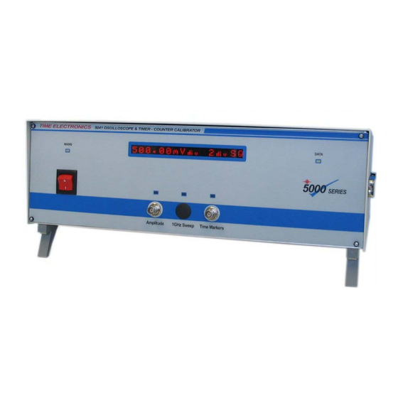
Page 7 3.5 Front Panel The LED indicators on the front panel are, Mains On, Amplitude, GHz Sweep, Time Markers and Data. The data transfer over the communications link is indicated by the Data led flashing. The 16-character alphanumeric display indicates the unit’s current output, e.g. the output frequency, period, or amplitude. -
Page 10: Output Connections
Output Connections There are 2 (or 3, if the GHz sweep option is fitted) connectors on the front panel of the 5041. From left to right these are: Amplitude Output The output from this connector is used to calibrate the amplitude scale of oscilloscopes. -
Page 11: Chapter 4 Operation
In GPIB mode the GPIB address will need to be set to match that which has been set on the 5041 (see Chp 3). Note that for GPIB operation the PC must have a GPIB adapter fitted and the relevant driver software installed. -
Page 12: Amplitude Function
Full information about the output signal is given in the main display window. The 5041 is capable of driving a 50 ohm termination with 2V DC or pk-pk signals. Note that the resulting accuracy is reduced - see Chp 2 specification. Also note that the final accuracy will be further reduced by the accuracy of the 50 ohm termination resistor. - Page 13 Page 11 Typical Amplitude outputs: Tektronix 7A22 1mV/div 1 MHz bandwidth LeCroy 9314AM digital 100mV/div, 50 ohm terminated, full bandwidth LeCroy 9314AM digital 2mV/div, 50 ohm terminated, full bandwidth (notice the internal scope generated noise)
-
Page 14: Fast Rise Function (Bandwidth Determination)
The bandwidth is calculated by first measuring the scopes displayed rise time using the very fast rising edge of the 5041’s fast-rise signal. The rise time value is then input to the program and a bandwidth calculated using a mathematical formula. The result is shown in the main display window. -
Page 15: Frequency (Time Base) Function
Page 13 Frequency (Time Base) Function The 5041 provides frequencies from 0.1Hz to 100MHz in two basic ranges. Low Range is 0.1Hz to 170kHz , and the High Range is 200kHz to 100MHz. This function is suitable for calibrating oscilloscope time bases and also timer-counters. - Page 16 Page 14 Examples of Frequency function outputs: Example of effect of a poor quality The same conditions with a good cable quality cable (Note the distortion effects) Example of a 20% Mark/Space output The 100MHz output displayed on a Tek 3000...
-
Page 17: Period Function
Page 15 Period Function The period function mirrors the frequency mode, again having two ranges. The Short Period Range provides fixed periods from 10ns to 5µs. The Long Period Range provides periods from 6µs to 15s. As with frequency the short period range has fixed values and the long period range has numeric keypad entry. -
Page 18: Ghz Levelised Sine Function
This function is selected from the main menu. The output is via the centre connector on the front panel. Please note that the 5041’s display is not active for this function. The frequency sweep is controlled by three sets of buttons which increment/decrement in 1, 10, 100MHz steps. - Page 19 Page 17 Oscilloscope Bandwidth and Frequency Response Calibration: An oscilloscope’s bandwidth and frequency response can be checked using a sine- wave signal that has an accurately controlled amplitude over a wide range of frequency. The absolute accuracy of the sine-wave is not important, only its stability with change in frequency.
-
Page 20: Chapter 5 Easycal
Please Note: In order to use EasyCal with the 5041 you must be using EasyCal version 5.25 or later. Adding the 5041 to the List of Calibration Instruments To use the 5041 with EasyCal, first you need to add it to the list of calibration instruments. To do this: 1) Start EasyEdit 2) Select menu option System Setup 3) Select menu option Calibration Instruments. - Page 21 Page 19 Entering Procedures that use the 5041 Now that the 5041 is in the list of EasyCal’s calibration instruments, it is easy to add tests to a procedure that use the 5041. Here are the steps involved: 1) Create a new procedure or open an existing procedure in the normal way using EasyEdit.
- Page 22 50% duty cycle. Input Method Choices are the standard EasyCal options. Included is Deviate. If selected, this allows the operator to deviate the output of the 5041 calibrator until the instrument under test reads the required voltage. Volts per Div Select the required volts per division from the choices available (1mV/Div to 50V/Div).
- Page 23 Required Value Select the required time-base from the list of available timebases (100ns to 10s). The 5041 will output a 50% duty cycle square wave of the selected period. The remaining fields are used in the normal way of EasyCal.
- Page 24 It is possible to measure the bandwidth of an oscilloscope using this type of test. The 5041 will output a square wave at 10MHz. By measuring the rise time of the instrument under test at calibration time, it is possible to determine the bandwidth of the instrument.
- Page 25 Duty cycle tests can be used to test the duty cycle function of an oscilloscope or timer/counter. As well as being able to select the duty cycle required, the test also includes a choice of periods, from 100µs to 5s. The 5041 outputs a square wave of the chosen duty cycle and of the selected period.
- Page 26 Page 24 Calibration Runs using the 5041 When performing a calibration run that uses the 5041 then, as with all calibration instruments, ensure that it is switched on and connected to the PC running EasyCal before you start the calibration run from the CalRun application.
- Page 27 The screen will look like this (if Keyboard Input method is selected, then it will vary slightly): Remember to connect a 50 Ohm termination between the oscilloscope and the Time Markers BNC connector of the 5041. To calculate the bandwidth of the oscilloscope: Configure the oscilloscope so that a single wave cycle fills the screen.
- Page 28 Page 26 Frequency Test Shown here is an example of a frequency test being performed. In this example, the input method is Keyboard Input – the screen will vary slightly for other input methods. Enter the frequency reading shown on the timer/counter or oscilloscope under test into the box labelled Reading.
-
Page 29: Chapter 6 Fault Diagnosis
Faulty items may be returned for repair or, replacement boards obtained. Please ensure you always quote your 5041’s serial number, and give exact details of the fault. Time Electronics and their authorised agents offer an exchange service for all modules and cards including the power module. -
Page 30: Mains Power Unit
3. The correct disposal of your old appliance will help prevent potential negative consequences for the environment and human health. 4. For more detailed information about disposal of your old appliance, please contact your city office, waste disposal service or return to Time Electronics. -
Page 31: Chapter 7 - Guarantee & Service Facilities
Chapter 7 - GUARANTEE AND SERVICE FACILITIES RETURNING - GUARANTEE PERIOD The 5041 is guaranteed against defects in materials and workmanship for a period of two years from its delivery to the customer. During this period, we will at our discretion, repair or replace the defective item.
Need help?
Do you have a question about the 5041 and is the answer not in the manual?
Questions and answers