Table of Contents
Advertisement
Quick Links
Advertisement
Table of Contents

Related Manuals for Time Electronics 5070


Summary of Contents for Time Electronics 5070
- Page 1 5070 Ductor Tester / Micro-Ohmmeter Calibrator Version 1.1 May 2021 Time Electronics Ltd Unit 5, TON Business Park, 2-8 Morley Road, Tonbridge, Kent, TN9 1RA, United Kingdom. T: +44 (0) 1732 355993 | F: +44 (0) 1732 350198 mail@timeelectronics.co.uk | www.timeelectronics.com...
- Page 2 All rights reserved. Nothing from this manual may be multiplied, or made public in any form or manner, either electronically or hard copy, without prior written consent from Time Electronics Ltd. This also applies to any schematics, drawings and diagrams contained herein.
-
Page 3: Table Of Contents
Time Electronics User Manual 5070 Ductor Tester and Micro-Ohmmeter Calibrator v1.1 Contents Introduction ............................2 Features ..............................2 Description ..............................2 Specifications .............................. 3 Operation ............................. 4 5070 Front Panel ............................4 Test Connection ............................6 Operating Precautions ..........................6 Warranty and Servicing ........................ -
Page 4: Introduction
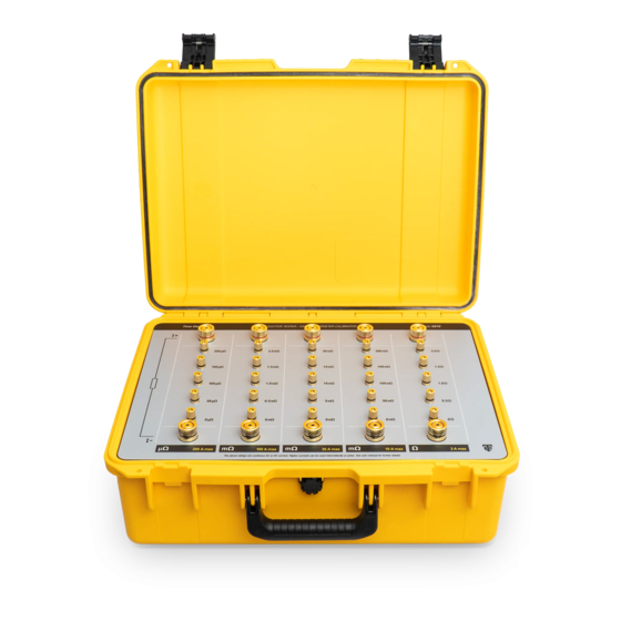
The internal resistance standards are high quality manganin types with good long term stability and temperature coefficients. Rugged and portable, the 5070 is ideal for site calibration work, housed in a safety yellow field case with carry handle. -
Page 5: Specifications
1000 A and a maximum applied time of 4 seconds. At least 1 minute should be allowed between applications for cooling. NOTE: It is important to ensure there are adequate low resistance connections to the 5070 current terminals. 1.3.1 General Specifications Dimensions ...... -
Page 6: Operation
Time Electronics User Manual 5070 Ductor Tester and Micro-Ohmmeter Calibrator v1.1 Operation The front panel contains 5 rows of high-quality gold-plated terminals. All are suitable for 4 mm plug insertion on screw compression connectors. For current connection, large 25 mm diameter terminals are provided. - Page 7 Example showing 200 μΩ range (200 A max) below. The voltage terminals are resistance set points that can be stepped through to perform 4-wire calibration of the unit under test. The 5070 has 5 independent ranges of resistance set points. VOLTAGE TERMINALS 200 μΩ...
-
Page 8: Test Connection
(current leads disconnected). The zero position is checked with the voltage potential leads from the unit being calibrated, connected together on the 5070’s ‘0’ voltage terminal. Page 6 of 8 5070 Ductor Tester and Micro-Ohmmeter Calibrator... -
Page 9: Warranty And Servicing
Time Electronics’ total liability is limited to repair or replacement of the product. Note that if Time Electronics determine that the fault on a returned product has been caused by the user, we will contact the customer before proceeding with any repair. - Page 10 Returning Instruments Prior to returning your product please contact Time Electronics. We will issue a return merchandise authorization (RMA) number that is to accompany the goods returning. Further instructions will also be issued prior to shipment. When returning instruments, please ensure that they have been adequately packed, preferably in the original packing supplied.
Need help?
Do you have a question about the 5070 and is the answer not in the manual?
Questions and answers