Table of Contents
Advertisement
Quick Links
Advertisement
Table of Contents

Related Manuals for Time Electronics 5018


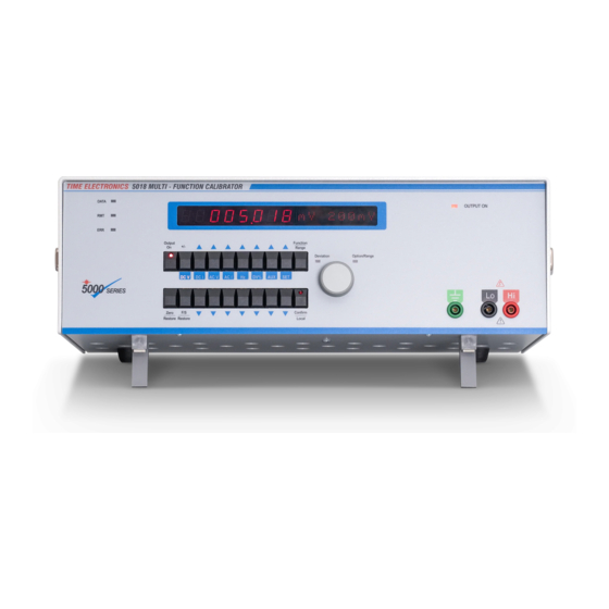
Summary of Contents for Time Electronics 5018
- Page 1 User Manual 5018 Programmable Voltage and Current Calibrator Revision 2206-1 Time Electronics Ltd Unit 5, TON Business Park, 2-8 Morley Road, Tonbridge, Kent, TN9 1RA, United Kingdom. T: +44 (0) 1732 355993 | F: +44 (0) 1732 350198 mail@timeelectronics.co.uk | www.timeelectronics.com...
- Page 2 All rights reserved. Nothing from this manual may be multiplied, or made public in any form or manner, either electronically or hard copy, without prior written consent from Time Electronics Ltd. This also applies to any schematics, drawings and diagrams contained herein.
-
Page 3: Table Of Contents
Time Electronics User Manual 5018 Programmable Voltage and Current Calibrator Revision 2206-1 Contents Introduction ............................ 4 Overview ..............................4 Important Information ..........................5 Specifications ............................6 Installation ............................. 8 Front Panel Controls ........................10 Keypad and Display ..........................10 Keypad Buttons ........................... 11 Display Readout .......................... -
Page 4: Introduction
19" rack mount kit is available for integration into a modular test equipment setup. GPIB, RS-232 and USB interfaces allow the 5018 to be connected to a PC and controlled by an external program such as EasyCal calibration software. The 5018 uses a SCPI command structure for programming. -
Page 5: Important Information
High Voltage The 5018 is capable of producing 1000 V and users should be aware of the dangers involving serious electrical shock. Warning: If this equipment is used in a manner not specified by the manufacturer, the protection provided by the equipment may be impaired. -
Page 6: Specifications
Time Electronics User Manual 5018 Programmable Voltage and Current Calibrator Revision 2206-1 Specifications 1.3.1 Technical Specifications Accuracy specifications are shown as ppm (or %) of output + floor and apply for settings between 10 % and 100 % of range. - Page 7 Time Electronics User Manual 5018 Programmable Voltage and Current Calibrator Revision 2206-1 1.3.2 General Specifications Warm up: 1 hour to full accuracy. Settling time: Less than 5 seconds. Standard interfaces: GPIB (IEEE-488), RS-232, USB. Temperature performance: Operating: 10 to 40 °C, Full Spec: 23 °C ± 5 °C, Storage: -10 to 50 °C.
-
Page 8: Installation
Positioning the Instrument Benchtop Use The 5018 should always be positioned on a flat, firm surface. The instrument base is fitted with four feet. The front feet have tilt legs to angle the instrument upwards for ergonomic front panel operation. - Page 9 Time Electronics User Manual 5018 Programmable Voltage and Current Calibrator Revision 2206-1 1.4.2 Mains (Line) Power Supply The supply power is connected via a standard IEC Euro connector on the rear panel. The standard voltage supply is 220/230 V 50 Hz. There are two protection fuses mounted on the rear panel next to the IEC connector, both are 3.15 A slow blow.
-
Page 10: Front Panel Controls
Time Electronics User Manual 5018 Programmable Voltage and Current Calibrator Revision 2206-1 Front Panel Controls Keypad and Display Display readout 0.0.0.0..0.0.0.0 2 0 m V Function Polarity button button Rotary knob mode LEDs Output on button Function DC V DC I... -
Page 11: Keypad Buttons
Time Electronics User Manual 5018 Programmable Voltage and Current Calibrator Revision 2206-1 Keypad Buttons 2.2.1 Function Selection Buttons Function selection is initiated by pressing the “Function/Range” button. The function indicators flash to prompt a selection. This informs the user that the buttons... -
Page 12: Display Readout
Time Electronics User Manual 5018 Programmable Voltage and Current Calibrator Revision 2206-1 2.2.2 Output Value Setting Buttons Setting an output value is performed by using the up/down buttons for the following functions: DC Voltage, DC Current, AC Voltage (option), AC Current (option). -
Page 13: Rotary Knob
Time Electronics User Manual 5018 Programmable Voltage and Current Calibrator Revision 2206-1 Rotary Knob The rotary knob is used to select ranges, settings and options. It is adjusted clockwise or anti-clockwise to the required selection. The “Deviation” or “Option/Range” LEDs illuminate to prompt usage of the rotary knob for the required operation. -
Page 14: Terminals
Time Electronics User Manual 5018 Programmable Voltage and Current Calibrator Revision 2206-1 Terminals The terminal configuration for the 5018. Terminal LED Indicator LED indicates active terminal: ON when outputting • FLASHING when in standby (no output) • Earth Terminal Main Output Terminals... -
Page 15: Display Leds
Time Electronics User Manual 5018 Programmable Voltage and Current Calibrator Revision 2206-1 Display LEDs Data and Remote LEDs Used to indicate remote mode activity. See “Remote Operation” section of this manual for more details. Error LED Flashes to indicate an output error condition, e.g. -
Page 16: Front Panel Operation
User Manual 5018 Programmable Voltage and Current Calibrator Revision 2206-1 Front Panel Operation Unit start-up After switching on, the 5018 goes through a start-up routine that includes: • Instrument self-test and health check routine. • Front panel LEDs illuminate. •... -
Page 17: How To Select A Function
Time Electronics User Manual 5018 Programmable Voltage and Current Calibrator Revision 2206-1 How to select a Function Press the “Function” button. DC V DC I AC V AC I 2. The function indicators will then flash to prompt a selection. -
Page 18: Dc Voltage Or Current Dcv Dci
Time Electronics User Manual 5018 Programmable Voltage and Current Calibrator Revision 2206-1 DC Voltage or Current DCV DCI DC Voltage and DC Current have common operation steps. Shown here is DC V. 1. Press the “Function” button then “DC V” button. - Page 19 Time Electronics User Manual 5018 Programmable Voltage and Current Calibrator Revision 2206-1 3. To set the required output voltage, increment or decrement the individual digits by using the “Up (∆) or Down (∇)” buttons. 0.0.0.3 .0.0.0.0 20mV DC V DC I...
- Page 20 Time Electronics User Manual 5018 Programmable Voltage and Current Calibrator Revision 2206-1 It is possible to set the output to zero in one step by pressing the “Zero” button. -.0.0.0 .0.0.0.0 20mV DC V DC I AC V AC I Return to the previous setting by pressing the “Zero”...
- Page 21 Time Electronics User Manual 5018 Programmable Voltage and Current Calibrator Revision 2206-1 4. Output is initially disconnected from the output terminals. This is indicated by the LED on the Output On button flashing (on for 25% of the time, off for 75% of the time).
- Page 22 Time Electronics User Manual 5018 Programmable Voltage and Current Calibrator Revision 2206-1 5. To change the output level, the Up (∆) / Down (∇) buttons can be used at any time. 0.0.0.3 .0.0.0.2 20mV DC V DC I AC V AC I If necessary, the output can be turned off by pressing the “Output On”...
- Page 23 Time Electronics User Manual 5018 Programmable Voltage and Current Calibrator Revision 2206-1 The present range will be shown flashing in the right-hand display. Next is a repeat of step 2 to 5, but select the new range required. 0.0.0.0.0.0.0.0 20mV...
-
Page 24: Using Deviation Mode Dv
Time Electronics User Manual 5018 Programmable Voltage and Current Calibrator Revision 2206-1 Using Deviation Mode DV% This feature allows the output to be deviated in percentage steps. There are 3 options: • Fine deviation: 0.001% • Medium deviation: 0.01% Coarse deviation: 0.1% •... - Page 25 Time Electronics User Manual 5018 Programmable Voltage and Current Calibrator Revision 2206-1 3. To adjust the deviation, turn the rotary knob clockwise to increase, and anticlockwise to decrease. -.0.0.0.3..0.0.0 mV -.022 DC V DC I AC V AC I Note: It is not possible to adjust the deviation if the output setting is zero, since the deviation is a percentage of value.
-
Page 26: Safety Interlock Feature
Time Electronics User Manual 5018 Programmable Voltage and Current Calibrator Revision 2206-1 Safety Interlock Feature When a high voltage option (code 9720 or 9721) is fitted there is a safety interlock feature incorporated for voltages above 40V. This ensures that the user must perform an additional action before the signal will appear at the terminals. -
Page 27: Ac Voltage Or Current (Option) Acv Aci
Time Electronics User Manual 5018 Programmable Voltage and Current Calibrator Revision 2206-1 AC Voltage or Current (option) ACV ACI AC Voltage and AC Current have common operation steps. Shown here is AC V. 1. Press the “Function” button then “AC V” button. - Page 28 Time Electronics User Manual 5018 Programmable Voltage and Current Calibrator Revision 2206-1 3. The frequency can be set by pressing “Function” button followed by the “Hz” button. DC V DC I AC V AC I Select the frequency using the “Up (∆) / Down (∇)” buttons.
- Page 29 Time Electronics User Manual 5018 Programmable Voltage and Current Calibrator Revision 2206-1 4. Once the frequency is set, the display readout will show the output voltage and operating range. The output value can be entered using the “Up (∆) / Down (∇)” buttons.
-
Page 30: Setup Options Set
Time Electronics User Manual 5018 Programmable Voltage and Current Calibrator Revision 2206-1 Setup Options SET 1. Press the “Function” button. DC V DC I AC V AC I 2. The function indicators will then flash to prompt a selection. Press the “SET” button. - Page 31 Time Electronics User Manual 5018 Programmable Voltage and Current Calibrator Revision 2206-1 3.7.2 Deviation Resolution (Dev Rsln) Deviation Resolution is the first menu shown when you enter the setup menu. It can be used with DC V, DC I, AC V, AC I.
-
Page 32: Remote Operation
The 5018 may be controlled by a PC via a RS-232, USB or GPIB. The unit must first be configured for the type of communications being used. With the 5018 switched off, locate the DIP switches on the rear panel. - Page 33 Address 5 (ON=16, OFF=0) Does not matter The GPIB address of the 5018 may be set between 0 and 30 (although address 0 is usually reserved for the GPIB controller, i.e. the PC). Convert the address into settings of the Address 1-5 DIP switches. For instance, if the address required is 22, then set the Address DIP switches to ON so that their values add up to 22, i.e.:...
- Page 34 Time Electronics User Manual 5018 Programmable Voltage and Current Calibrator Revision 2206-1 4.1.3 Entering Remote Mode The unit will automatically enter remote mode as soon as it receives a command on the remote interface. While in remote mode, the keypad will be disabled apart from the Confirm/Local key.
-
Page 35: Remote Commands
Time Electronics User Manual 5018 Programmable Voltage and Current Calibrator Revision 2206-1 Remote Commands 4.2.1 Introduction to SCPI The 5011’s remote commands follow the SCPI standards. If you are already familiar with SCPI, then you can skip this section. SCPI commands are based on a tree-like hierarchy. Associated commands are grouped together under a common node (or root), into “subsystems”. - Page 36 Time Electronics User Manual 5018 Programmable Voltage and Current Calibrator Revision 2206-1 Triangle brackets (<,>) are used to indicate a value you need to specify for the parameter. For example, with the command above a valid command would be: SOUR:VOLT:RANG 10 If a parameter or command keyword is enclosed in square brackets ([,]) then it is optional and can be omitted.
- Page 37 Time Electronics User Manual 5018 Programmable Voltage and Current Calibrator Revision 2206-1 Parameter Types Numerical Parameters Commands that accept numerical values as parameters also allow units to be specified, e.g. mV, uA, C (deg C), kR (kilo-ohms). For instance all of these are valid:...
- Page 38 Time Electronics User Manual 5018 Programmable Voltage and Current Calibrator Revision 2206-1 4.2.2 Command Set [:SOURce]:VOLTage:RANGe <volts> Select the voltage function and a range. <volts> may be 20mv, 200mv, 2V, 20V, 200V or 1kV. Example: volt:rang 20 selects the voltage function and 20V range [:SOURce]:VOLTage:RANGe? Query the present voltage range.
- Page 39 Time Electronics User Manual 5018 Programmable Voltage and Current Calibrator Revision 2206-1 [:SOURce]:CURRent[:LEVel][:IMMediate][:AMPLitude] <amps> Set the current output in the present current range. Example: curr 0.5 sets the output current to 500mA [:SOURce]:CURRent[:LEVel][:IMMediate][:AMPLitude]? Query the present current output. Example: curr? >...
- Page 40 Time Electronics User Manual 5018 Programmable Voltage and Current Calibrator Revision 2206-1 Set all outputs off and return the unit to the “Ready” state. Note, the unit is still in remote mode operation. Example: none :OUTPut[:STATe] <Boolean> Turns output from the terminals on (if <Boolean> is ON) or off (if <Boolean> is OFF). At startup, the default state is ON.
- Page 41 Time Electronics User Manual 5018 Programmable Voltage and Current Calibrator Revision 2206-1 :SYSTem:VERSion? Query the version of SCPI supported by the unit. Example: syst:vers? > 1999.0 :SYSTem:UNIT:INFormation? Query the version numbers of the unit’s firmware and the modules within the unit. The format of the returned information is one line of text per module: <Board Code>,<Software version>...
- Page 42 Time Electronics User Manual 5018 Programmable Voltage and Current Calibrator Revision 2206-1 IEEE488.2 Compliant Commands *CLS Clear the remote error buffer. *IDN? Query the identity of the unit. The information returned is in standard SCPI format, i.e.: TIME ELECTRONICS,5018,0,1.0.0 where 1.0.0 is the version number of the unit’s firmware.
-
Page 43: Ramping
PC to perform the actual ramping function. The ramping option can be set to on or off via the 5018 front panel by pressing the ‘function’ button followed by the ‘Set’ button and selecting the ramp on/off option. This enables the 5018 to operate in normal output mode if required. -
Page 44: Remote Commands
5018 Programmable Voltage and Current Calibrator Revision 2206-1 Remote Commands The 5018 must be put into the correct range before sending the ramp rate command. :VOLTage:RAMP:RATe Set the voltage ramp rate for the select range in Volts/Sec. (smooth ramping) :VOLTage:RAMP:RATe? -
Page 45: Fault Diagnosis
Time Electronics User Manual 5018 Programmable Voltage and Current Calibrator Revision 2206-1 Fault Diagnosis Startup Errors If the unit displays one or more error codes at startup, then refer to this table: Error Meaning Displayed The voltage and current calibration factors are invalid. The unit should be V/I Cal! calibrated/recalibrated before the voltage and current functions are used again. -
Page 46: Re-Calibration
Revision 2206-1 Re-Calibration The 5018 should be re-calibrated at recommended intervals in order to ensure its outputs remain within specification. Normally re-calibration is done at 12 month intervals. The 5018 calibration software and manual are supplied separately and only available by request from Time Electronics. -
Page 47: Warranty And Servicing
Time Electronics’ total liability is limited to repair or replacement of the product. Note that if Time Electronics determine that the fault on a returned product has been caused by the user, we will contact the customer before proceeding with any repair. - Page 48 Revision 2206-1 Returning Instruments Prior to returning your product please contact Time Electronics. We will issue a return merchandise authorization (RMA) number that is to accompany the goods returning. Further instructions will also be issued prior to shipment. When returning instruments, please ensure that they have been adequately packed, preferably in the original packing supplied.
Need help?
Do you have a question about the 5018 and is the answer not in the manual?
Questions and answers