Table of Contents
Advertisement
Quick Links
Advertisement
Table of Contents

Related Manuals for Time Electronics 1024


Summary of Contents for Time Electronics 1024
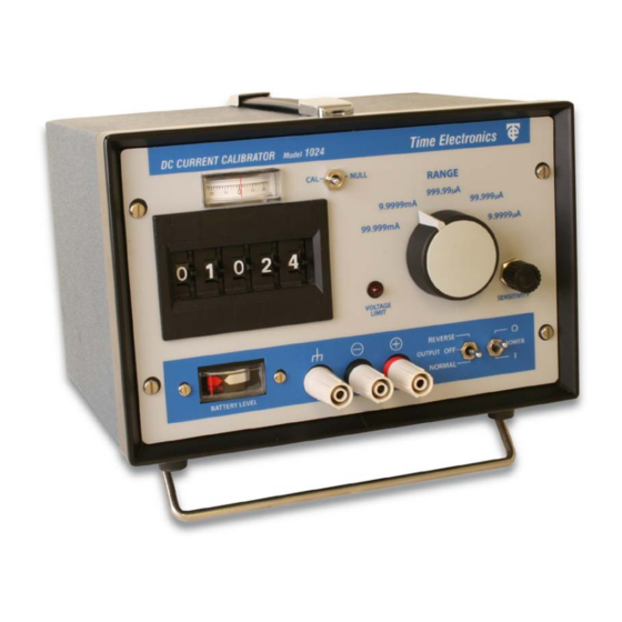
- Page 1 Time Electronics 1024 DC Current Calibrator With Null Measuring Facility Technical Manual V1.1 20/04/09 Time Electronics Ltd Botany Industrial Estate, Tonbridge, Kent, TN9 1RH Tel: +44(0)1732 355993 Fax: +44(0)1732 770312 Email: mail@TimeElectronics.co.uk Web Site: www.TimeElectronics.com...
-
Page 2: Table Of Contents
Calibration Procedure ....................12 4.2.2. Linearity ........................12 Guarantee & Servicing ..................13 All Time Electronics' instruments are subject to continuous development and improvement and in consequence may incorporate minor detail changes from the information contained herein. 1024 Technical Manual... -
Page 3: Introduction
• Portable • Battery & mains operation The 1024 is a solid state battery powered instrument which is easily portable and convenient for laboratory, field, or industrial use. It incorporates many of the well-proven circuit techniques of the Time Electronics Type 1010 DC Voltage Calibrator. -
Page 4: Specifications
Power supply: Time Electronics power unit type PU2 which is housed in the rear of the 1024. The PU2 will power the 1024 direct from the mains or an internal rechargeable battery. The battery is automatically charged when mains power is connected. -
Page 5: Operation
2.1. Front Panel Controls a) Output terminals The 1024 output current is from two front panel terminals which are suitable for wire compression or 4mm plug insertion. The output current will flow from the + (red) terminal when the polarity switch is ‘normal’. - Page 6 Null Meter Scaled 0 to 25 for displaying the difference current when the 1024 is used in the null mode. j) Sensitivity Control A continuously variable control for adjusting the null meter sensitivity, range of adjustment is from 25mA minimum (fully anticlockwise) to 25uA maximum (fully clockwise).
-
Page 7: Operating Procedures And Precautions
The 1024 can withstand indefinitely either short or open circuit on the output terminals. Overload conditions can easily result if any attempt is made to drive current into the 1024 by applying a voltage to the output terminals. In most cases this will cause the output fuse (See Section 2.5) to blow but can still cause damage to the output circuitry. - Page 8 Its effect on the 1024 is to cause a transient variation in the output which can last longer than the actual duration of the noise. This is because the 1024 has been transiently over- loaded and needs time to recover.
-
Page 9: Mains Power Unit
Note: Take care not to short any part of the circuitry when converting a PU2. 3) Connect mains transformer windings in parallel by rewiring the mains input to the transformer (As shown on the side of the transformer). 4) Replace the screening cover. 1024 Technical Manual... -
Page 10: Constructional Layout Details
It is important to ensure that no strain is put on the connector when the nuts are finally tightened. 8) Set Module zero and recalibrate as described on the following page. 1024 Technical Manual... -
Page 11: Recalibration
One provides adjustment of the zero and the other full scale. If readjustment is necessary the output should be set up against suitable standards. Due to the precision nature of many of the components used in the 1024, they are not readily available to enable the customer to undertake repairs. -
Page 12: Calibration Procedure
P.C.B. The other 2 trimmers are located on the side of the encapsulated circuit block and marked ‘CAL’ and ‘ZERO’. Switch on the 1024 and allow the circuits to stabilise for a few minutes. Ensure that no draughts or direct heating (e.g. sunlight) affect the 1024’s circuitry. -
Page 13: Guarantee & Servicing
We maintain comprehensive after sales facilities and the unit can, if necessary be returned to us for servicing. During this period, Time Electronics Ltd will, at its discretion, repair or replace the defective items. For servicing under guarantee, the instrument type and serial number must always be quoted, together with details of any fault and the service required.
Need help?
Do you have a question about the 1024 and is the answer not in the manual?
Questions and answers