Table of Contents
Advertisement
Quick Links
Advertisement
Table of Contents

Related Manuals for Time Electronics 5051 Plus


Summary of Contents for Time Electronics 5051 Plus
- Page 1 User Manual Multifunction Calibrators 5051 Plus 7051 Plus Version 2.1 April 2021 Time Electronics Ltd Unit 5, TON Business Park, 2-8 Morley Road, Tonbridge, Kent, TN9 1RA, United Kingdom. T: +44 (0) 1732 355993 | F: +44 (0) 1732 350198...
- Page 2 This manual provides operating and safety instructions for the Time Electronics product. To ensure correct operation and safety, please follow the instructions in this manual. Time Electronics reserves the right to change the contents, specifications and other information contained in this manual without notice.
-
Page 3: Table Of Contents
Time Electronics User Manual 5051 Plus and 7051 Plus Multifunction Calibrators v2.1 Contents 1. Introduction ........................5 1.1. Features ..............................5 1.2. Calibration Capabilities .......................... 5 2. Specifications ........................ 6 2.1. Calibrator (Source) ..........................6 2.2. 6.5 Digit Multimeter (measure) ......................6 2.3. - Page 4 13. Warranty and Servicing ....................63 NOTE: The 7051 Plus / 5051 Plus are a packages that includes specific options for a wide workload coverage. This manual will refer to the 7051 or 5051 in certain sections as an abbreviation.
-
Page 5: Introduction
Time Electronics User Manual 5051 Plus and 7051 Plus Multifunction Calibrators v2.1 Introduction The xx51Plus combines a high accuracy calibration source with a precision digital multimeter. It incorporates a wide range of internally fitted functions to provide users with a multi product calibration solution. -
Page 6: Specifications
Time Electronics User Manual 5051 Plus and 7051 Plus Multifunction Calibrators v2.1 Specifications 2.1. Calibrator (Source) Function Range / Values Best 1 Year Specification Voltage DC 0 to ± 1050V ± 15ppm of setting Current DC 0 to ± 22A ±... -
Page 7: 7051 Control Centre Details
Time Electronics User Manual 5051 Plus and 7051 Plus Multifunction Calibrators v2.1 2.3. 7051 Control Centre Details Feature Specifications Processor 64 bit, dual core (or equivalent) 16GB Hard Drive 120GB Solid State (or higher) Ports Front: 4 x USB / Rear: 2 x USB, 2 x RS-232 Display 12.1”... -
Page 8: 5051 Control Centre Details
Time Electronics User Manual 5051 Plus and 7051 Plus Multifunction Calibrators v2.1 2.5. 5051 Control Centre Details Feature Specifications Processor 64 bit, dual core (or equivalent) 4GB (or higher) Hard Drive 120GB Solid State (or higher) Ports 4 x USB, 1 x Fast Ethernet Display 10.4”... -
Page 9: General Safety Precautions
Time Electronics User Manual 5051 Plus and 7051 Plus Multifunction Calibrators v2.1 General Safety Precautions High Voltage: The xx51 can produce 1050 V and users should be aware of the dangers involving serious electrical shock. High Current: The xx51 can produce 22 Amps and users should be aware of the power levels involved. -
Page 10: Plus
Time Electronics User Manual 5051 Plus and 7051 Plus Multifunction Calibrators v2.1 7051 Plus 5.1. Standard 7051Plus 5.2. 7051Plus With CCPAD Option The CCPAD is a module designed to accompany the CalBench control centre, for use with the manual control programs and EasyCal calibration software. -
Page 11: 7051 Terminal Panel
Time Electronics User Manual 5051 Plus and 7051 Plus Multifunction Calibrators v2.1 5.3. 7051 Terminal Panel The terminal panel locates to the right side of the control centre module and features a Measure and Source section. Multimeter Section DCV to 1 kV •... -
Page 12: Plus
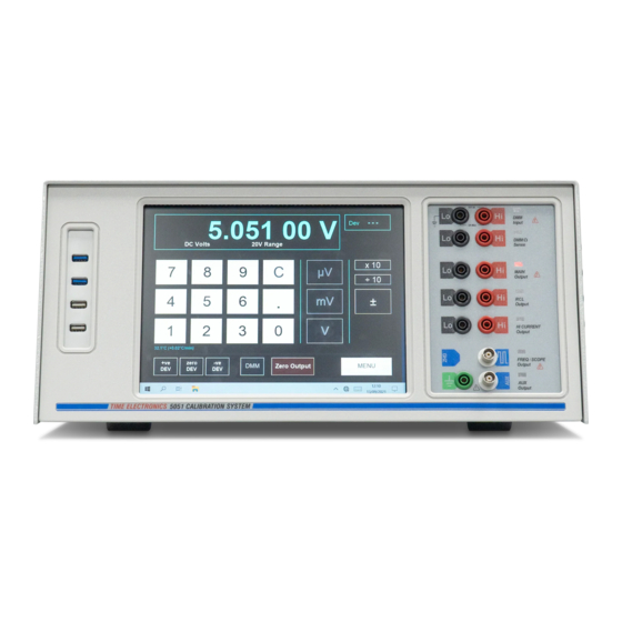
Time Electronics User Manual 5051 Plus and 7051 Plus Multifunction Calibrators v2.1 5051 Plus 6.1. 5051 Plus Important Information Warning: The 5051 is a heavy instrument and care should be taken when lifting to prevent injury. Use both handles to carry. -
Page 13: 5051 Terminal Panel
Time Electronics User Manual 5051 Plus and 7051 Plus Multifunction Calibrators v2.1 6.2. 5051 Terminal Panel Multimeter Section • DCV to 1 kV • ACV to 750 V • DCI / ACI to 3 A • Resistance: 0 to 100 MΩ... -
Page 14: Operation
Time Electronics User Manual 5051 Plus and 7051 Plus Multifunction Calibrators v2.1 Operation After completing the power-up initialisation the Control Centre will show the conventional Windows desktop on the screen. The start menu is set up for the following applications: EasyCal •... -
Page 15: Operating The Xx51 As A Calibrator
Time Electronics User Manual 5051 Plus and 7051 Plus Multifunction Calibrators v2.1 7.1. Operating the xx51 as a calibrator To use the xx51 as a high accuracy calibration source, click or touch the xx51 calibrator icon from the start menu. The program will initialise the xx51 before entering the FUNCTION selection screen... -
Page 16: Dc Voltage
Time Electronics User Manual 5051 Plus and 7051 Plus Multifunction Calibrators v2.1 7.2. DC Voltage DC V At the top of the screen is a sub window, which displays in large characters the output value and units. In small characters below are shown the range and function selected. -
Page 17: Setting The Output Value
Time Electronics User Manual 5051 Plus and 7051 Plus Multifunction Calibrators v2.1 7.2.1. Setting the Output Value DC V Zero Output Please note, at all times, pressing the button will set the output terminals to 0V. A conventional numeric keypad is used for setting the output. Enter the value required using the digit buttons. -
Page 18: Dc Voltage Connection Diagram
Time Electronics User Manual 5051 Plus and 7051 Plus Multifunction Calibrators v2.1 7.2.2. DC Voltage Connection Diagram DC V xx51+ Multifunction Calibrators Page 18 of 64... -
Page 19: Hv Interlock And Ramping
Time Electronics User Manual 5051 Plus and 7051 Plus Multifunction Calibrators v2.1 7.2.3. HV interlock and ramping DC V A safety interlock feature is incorporated to ensure that user must undertake an additional operation when voltages about 40V are selected. -
Page 20: Varying The Output Level
Time Electronics User Manual 5051 Plus and 7051 Plus Multifunction Calibrators v2.1 7.2.4. Varying the Output Level DC V Once an output level has been set, it may be varied in the following ways: Its polarity can be toggled using the +/- button •... - Page 21 Time Electronics User Manual 5051 Plus and 7051 Plus Multifunction Calibrators v2.1 DC V To apply a positive amount of deviation, use the + Dev button. To apply a negative amount of deviation, use the – Dev button. Clicking and releasing either button once will step the deviation by one count, i.e. +/-0.001%.
-
Page 22: Monitoring The Internal Temperature
Time Electronics User Manual 5051 Plus and 7051 Plus Multifunction Calibrators v2.1 7.2.6. Monitoring the Internal Temperature To operate within specification, the xx51 must be located in a stable environment at 22ºC +/- 3degC. It is also important that the internal temperature has stabilised. This is constantly displayed on the screen below the numeric keypad: 30.0ºC (+0.03ºC/min) -
Page 23: Dc Current
Time Electronics User Manual 5051 Plus and 7051 Plus Multifunction Calibrators v2.1 7.3. DC Current DC I The layout and usage of this screen is almost identical to the screen used for setting DC V. For common controls such as setting the output and using deviation, please refer to the DC V section. -
Page 24: Dc Current Connection Diagrams
Time Electronics User Manual 5051 Plus and 7051 Plus Multifunction Calibrators v2.1 7.3.2. DC Current Connection Diagrams DC I DC Current (DC A) < 200 mA DC Current (DC A) > 200 mA xx51+ Multifunction Calibrators Page 24 of 64... -
Page 25: Output Error
Time Electronics User Manual 5051 Plus and 7051 Plus Multifunction Calibrators v2.1 7.3.3. Output Error DC I Should the load attached to the output terminals be too high in value (e.g. an open circuit), and the set output is non-zero, a warning will be displayed at the base of the readout window. This condition occurs when the xx51 is unable to provide sufficient compliance voltage to the load. -
Page 26: Ac Voltage
Time Electronics User Manual 5051 Plus and 7051 Plus Multifunction Calibrators v2.1 7.4. AC Voltage AC V The selection process for AC voltage is identical to DC voltage with an additional option to set the frequency by using the Hz button (which replaces the +/- button on the DCV screen). After the output value has been set, the value of the required frequency is input using the digit buttons followed by the Hz button. -
Page 27: Ac Voltage Connection Diagrams
Time Electronics User Manual 5051 Plus and 7051 Plus Multifunction Calibrators v2.1 7.4.4. AC Voltage Connection Diagrams AC V AC Voltage (AC V) AC Voltage (AC V) > 20 kHz xx51+ Multifunction Calibrators Page 27 of 64... -
Page 28: Ac Current
Time Electronics User Manual 5051 Plus and 7051 Plus Multifunction Calibrators v2.1 7.5. AC Current AC I The operation of the ACI screen is the same as DCI. In addition, the frequency of the output may be set by entering a value using the numeric keypad and then pressing the Hz button. The present frequency is shown in the top-right corner of the screen. -
Page 29: Ac Current Connection Diagrams
Time Electronics User Manual 5051 Plus and 7051 Plus Multifunction Calibrators v2.1 7.5.2. AC Current Connection Diagrams AC I AC Current (AC A) < 200 mA AC Current (AC A) > 200 mA xx51+ Multifunction Calibrators Page 29 of 64... -
Page 30: R-G-C-L Function Selection
Time Electronics User Manual 5051 Plus and 7051 Plus Multifunction Calibrators v2.1 7.6. R-G-C-L Function Selection R-G-C-L R-G-C-L: R = Resistance • G = Conductance • C = Capacitance • • L = Inductance By pressing the R-G-C-L button on the main function selection screen, a new menu is displayed: This R-G-C-L function selection screen allows selection of any of the resistance, conductance, capacitance and inductance functions. -
Page 31: R-G-C-L Connection Diagram
Time Electronics User Manual 5051 Plus and 7051 Plus Multifunction Calibrators v2.1 7.6.2. R-G-C-L Connection Diagram R-G-C-L Connection is via the RCL Output terminals for these functions: xx51+ Multifunction Calibrators Page 31 of 64... -
Page 32: Decade Resistance
Time Electronics User Manual 5051 Plus and 7051 Plus Multifunction Calibrators v2.1 7.6.3. Decade Resistance Decade Resistance Decade (or fixed) resistance is selected on the R-G-C-L menu. If the 4-wire decade resistance option is fitted, the function will output through both MAIN and RCL terminals. -
Page 33: Full Range Resistance
Time Electronics User Manual 5051 Plus and 7051 Plus Multifunction Calibrators v2.1 7.6.4. Full Range Resistance Full Range Resistance Any resistance output between 1 ohm and 120M ohms may be selected. 7.6.4.1. Setting the Output Value Enter the value required using the numeric keypad. Then press one of the unit buttons to set the output. -
Page 34: Conductance
Time Electronics User Manual 5051 Plus and 7051 Plus Multifunction Calibrators v2.1 7.6.5. Conductance Conductance Conductance is available on the R-G-C-L function menu screen. 7.6.5.1. Setting the Output Value Press the output button required in the main area of the screen. The new output will be applied to the output terminals, and the readout at the top of the screen will display the new value. -
Page 35: Capacitance
Time Electronics User Manual 5051 Plus and 7051 Plus Multifunction Calibrators v2.1 7.6.6. Capacitance Capacitance Capacitance is selected on the R-G-C-L function menu screen. 7.6.6.1. Selecting an Output Value Press the output button required in the main area of the screen. -
Page 36: Inductance
Time Electronics User Manual 5051 Plus and 7051 Plus Multifunction Calibrators v2.1 7.6.7. Inductance Inductance Inductance is selected on the R-G-C-L function menu screen. 7.6.7.1.1. Selecting an Output Value Press the output button required in the main area of the screen. Eleven values of inductance are available, 1mH to 10H. -
Page 37: Temperature Simulation Selection
Time Electronics User Manual 5051 Plus and 7051 Plus Multifunction Calibrators v2.1 7.8. Temperature Simulation Selection Both thermocouple and PRT simulation is available. The thermocouple simulation is via the xx51’s precision voltage source. Accurate translation from temperature to voltage is via the ISO standard conversion tables for the thermocouple types specified and accuracy is as given in the extended specifications supplied with this manual. -
Page 38: Prt Simulation
Time Electronics User Manual 5051 Plus and 7051 Plus Multifunction Calibrators v2.1 7.8.1. PRT Simulation Any temperature between -200ºC and 850ºC may be simulated. 7.8.1.1. Selecting the Output Value Enter the output required using the numeric keypad and then press the ºC button to set the output. -
Page 39: Thermocouple Simulation
Time Electronics User Manual 5051 Plus and 7051 Plus Multifunction Calibrators v2.1 7.8.2. Thermocouple Simulation Thermocouple There are eight types of thermocouple that may be simulated, each selected from the Temperature function selection screen. The range of temperatures that can be simulated depends on the type of thermocouple selected: 0ºC to 1820ºC... - Page 40 Time Electronics User Manual 5051 Plus and 7051 Plus Multifunction Calibrators v2.1 Thermocouple The user should be aware of the errors that can occur due to thermal emfs and loading. For output equivalent to 22mV or less, the xx51’s output resistance is 10 ohms.
-
Page 41: Oscilloscope Calibration
Time Electronics User Manual 5051 Plus and 7051 Plus Multifunction Calibrators v2.1 7.9. Oscilloscope Calibration Scope Cal The xx51Plus is fitted as standard with an oscilloscope calibration feature. The following functions are provided: 1) Amplitude signals for calibrating the ‘Y’ channels 2) Time Markers for the Time Base calibration 3) Frequency for fixed outputs between 0.1Hz and 100MHz... -
Page 42: Amplitude
Time Electronics User Manual 5051 Plus and 7051 Plus Multifunction Calibrators v2.1 7.9.1. Amplitude Amplitude The Amplitude function is suitable for driving high impedance inputs. It allows outputs between 5mV and 220V. The output waveform may be either DC or a 1kHz square wave. -
Page 43: Amplitude (50 Ohm)
Time Electronics User Manual 5051 Plus and 7051 Plus Multifunction Calibrators v2.1 7.9.2. Amplitude (50 ohm) Amplitude (50 Ohm) The Amplitude (50 ohm) function is suitable for driving a 50 ohm inputs. It allows outputs between 5mV and 2.2V. The output waveform may be either DC or a 1kHz square wave. -
Page 44: Time Markers / Period
Time Electronics User Manual 5051 Plus and 7051 Plus Multifunction Calibrators v2.1 7.9.3. Time Markers / Period Time Markers The time marker function allows output signals of fixed periods between 10ns and 10s. 7.9.3.1. Setting the Output The available time marker outputs are split into 3 ranges: •... -
Page 45: Frequency
Time Electronics User Manual 5051 Plus and 7051 Plus Multifunction Calibrators v2.1 7.9.4. Frequency Frequency This function allows selection of fixed frequency outputs between 0.1Hz and 100MHz. 7.9.4.1. Setting the Output Because of the large number of spot frequencies available, they are split into 3 ranges for display purposes: 0.1Hz to 100Hz... -
Page 46: Duty Cycle
Time Electronics User Manual 5051 Plus and 7051 Plus Multifunction Calibrators v2.1 7.9.5. Duty Cycle Duty Cycle This function allows selection of duty cycle output between 0% and 100% at 3 selectable frequencies. 7.9.5.1. Setting the Output Enter the duty cycle required as percentage using the digit buttons, then press the % button to set the output. -
Page 47: Bandwidth (Via Fast Rise)
Time Electronics User Manual 5051 Plus and 7051 Plus Multifunction Calibrators v2.1 7.9.6. Bandwidth (via fast rise) Bandwidth (via fast rise) The Bandwidth function provides a means for calculating the approximate bandwidth of an oscilloscope. Selecting this function provides the fast rise-time signal needed for the determination of a scope’s rise time. - Page 48 Time Electronics User Manual 5051 Plus and 7051 Plus Multifunction Calibrators v2.1 Bandwidth (via fast rise) Shown below is an example of bandwidth determination of a TEK 3032 oscilloscope using the xx51’s fast signal. The measured rise time is about 1ns If 1ns is entered into the xx51’s bandwidth screen, a bandwidth of 350 MHz is shown, which is approximately correct for this scope.
-
Page 49: Ghz Sweep
Time Electronics User Manual 5051 Plus and 7051 Plus Multifunction Calibrators v2.1 7.9.7. GHz Sweep GHz Sweep The GHZ output is 10MHz to 2.2GHz – 1V PK to PK 7.9.7.1. Setting the Output A conventional numeric keypad is used for setting the frequency. Enter the value required using the digit buttons. -
Page 50: System Information
Time Electronics User Manual 5051 Plus and 7051 Plus Multifunction Calibrators v2.1 7.10. System Information Pressing the options button will display this screen: V-Source 28.3ºC Resistance 22.6ºC In the green band near the top of the screen is displayed the version number of the control program itself (e.g. -
Page 51: Operating The Xx51 As A Multimeter
Time Electronics User Manual 5051 Plus and 7051 Plus Multifunction Calibrators v2.1 7.11. Operating the xx51 as a Multimeter To use the xx51 as a multimeter, double-click the xx51 DMM icon on the Windows desktop. A screen will appear as below: Use only the ‘DMM’... -
Page 52: Selecting Range
Time Electronics User Manual 5051 Plus and 7051 Plus Multifunction Calibrators v2.1 7.11.2. Selecting Range The ranges available depend on the function selected. The ranges available are: Function Ranges DC Volts 100mV, 10mV, 1V, 10V, 100V, 1kV 100mV, 10mV, 1V, 10V, 100V, 1kV... -
Page 53: Reading Hold
Time Electronics User Manual 5051 Plus and 7051 Plus Multifunction Calibrators v2.1 7.11.4. Reading Hold If you wish to hold the display reading, click on the HOLD button. To indicate that Hold is active, the HOLD button will be highlighted and a HOLD annunciator will light up in the display window: While in HOLD state, no further readings will be taken –... -
Page 54: Easycal Software
Time Electronics User Manual 5051 Plus and 7051 Plus Multifunction Calibrators v2.1 EasyCal Software EasyCal Software is supplied as standard with the xx51Plus. It is pre-loaded on the control centre PC and configured for use upon start up. Full details of how to use the software are provided in the separate EasyCal manual. -
Page 55: Pressure Control Centre
Time Electronics User Manual 5051 Plus and 7051 Plus Multifunction Calibrators v2.1 7051 Pressure Control Centre If the CalBench features pressure modules RMTEG, MTEG or XTEG, the 7051 control centre will also feature a “Pressure Control Centre” application that can be accessed from the start menu by selecting this icon: The application provides a readback display via the control centre module. -
Page 56: Controls
Time Electronics User Manual 5051 Plus and 7051 Plus Multifunction Calibrators v2.1 9.1. Controls To view a pressure measurement; follow these steps: 1. Select the pressure module and port range from the Pressure Instrument list. 2. Touch the required units button for measurement. -
Page 57: Included Accessories
Time Electronics User Manual 5051 Plus and 7051 Plus Multifunction Calibrators v2.1 Included Accessories Item Description and Purpose Photo 9796 Test Lead Set Test leads used for connecting to various units under test, from the xx51 source and measure panel. - Page 58 Time Electronics User Manual 5051 Plus and 7051 Plus Multifunction Calibrators v2.1 7112 Transducer Patch Box (7051 Only) Provides convenient connection for transducers under test, with 250Ω resistor. 9795 Printer and Connectivity Kit USB keyboard and mouse, Inkjet Printer, Cal and ID Label Printer, 4 port USB hub, Numeric keypad, USB memory stick.
-
Page 59: Using The 9780 Clamp Meter Adaptor
Time Electronics User Manual 5051 Plus and 7051 Plus Multifunction Calibrators v2.1 10.1. Using the 9780 Clamp Meter Adaptor The 9780 is an adaptor used when calibrating clamp meters. Connect the clamp meter adaptor x50 coil to the xx51 Hi Current terminals. -
Page 60: 7112 Transducer Patch Box (7051 Only)
Time Electronics User Manual 5051 Plus and 7051 Plus Multifunction Calibrators v2.1 10.2. 7112 Transducer Patch Box (7051 Only) When testing instrumentation such as pressure transmitters you will use a combination of modules. The optimal set up utilizes the 7112 transducer patch box also. -
Page 61: 7051 Ccpad Option
Time Electronics User Manual 5051 Plus and 7051 Plus Multifunction Calibrators v2.1 10.3. 7051 CCPAD Option The CCPAD is a common accompanying module for the 7051Plus. It’s primary operation is with EasyCal software. Please see the CCPAD user manual for further details. -
Page 62: Re-Calibration
PC and malfunction of one of more of the many microcontrollers located inside the unit. Time Electronics maintain a technical support service and in the event of difficulty we are ready to provide technical advice by telephone, fax, or email. -
Page 63: Warranty And Servicing
Electronics’ total liability is limited to repair or replacement of the product. Note that if Time Electronics determine that the fault on a returned product has been caused by the user, we will contact the customer before proceeding with any repair. - Page 64 Returning Instruments Prior to returning your product please contact Time Electronics. We will issue a return merchandise authorization (RMA) number that is to accompany the goods returning. Further instructions will also be issued prior to shipment. When returning instruments, please ensure that they have been adequately packed, preferably in the original packing supplied.
Need help?
Do you have a question about the 5051 Plus and is the answer not in the manual?
Questions and answers