Table of Contents
Advertisement
Quick Links
Advertisement
Table of Contents

Related Manuals for turck DW108


Summary of Contents for turck DW108
- Page 1 Your Global Automation Partner CANopen Draw Wire DW108/DW124...
-
Page 2: Table Of Contents
Table of Contents General Information Symbols used / Warnings and Safety instructions Transport / Storage Product Description Technical Data DW108 Technical Data DW124 Interface Description CANopen Installation Electrical Installation 3.1.1 General Information for the Connection 3.1.2 Terminal Assignment Mechanical Installation 3.2.1... - Page 3 4.5.3 PDO Mapping Angle Examples 4.6.1 Example: basic parameterizing General CANopen Error Codes Annex Decimal / Hexadecimal conversion table Glossary...
-
Page 4: General Information
1 General Information Please read this document carefully before working with the product, mounting it or starting it up. 1.1 Symbols used / Warnings and Safety instructions Classification: DANGER This symbol, together with the signal word DANGER, warns against immediately imminent threat to life and health of persons. -
Page 5: Product Description
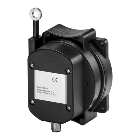
2 Product Description 2.1 Technical Data DW108 Measuring range 1 - 5 m Measuring wire material Nylon-coated AISI304 steel wire ø 0.9 mm Diameter Wire fastening Eyelet Inside diameter ø 8 mm Outside diameter Height ø 15 mm Height 2 mm Max. -
Page 6: Technical Data Dw124
2.2 Technical Data DW124 Measuring range 6.0 - 10.0 m Measuring wire material Nylon-coated AISI304 steel wire ø 0.9 mm Diameter Wire fastening Eyelet Inside diameter ø 8 mm Outside diameter Height ø 15 mm Height 2 mm Max. wire pull-out speed max. -
Page 7: Interface Description Canopen
2.3 Interface Description CANopen The CANopen protocol is a standardized layer 7 protocol for the CAN bus. The CANopen protocol defines on the one hand the "How" of the communication, that is to say with which telegrams (i.e. identifiers) the devices can be addressed. CANopen implements as well mecha- nisms for the exchange of process data in real-time as the transmission of large data volumes or the sending of alarm telegrams. -
Page 8: Installation
3 Installation 3.1 Electrical Installation 3.1.1 General Information for the Connection ATTENTION Destruction of the device Before connecting or disconnecting the signal cable, always disconnect the power supply and secure it against switching on again. NOTICE General safety instructions Make sure that the whole plant remains switched off during the electrical installation. •... -
Page 9: Sensor Orientation
3.2.1 Sensor Orientation During mechanical installation, take care to the orientation and to the angle range of the sensor. -
Page 10: Commissioning And Operation
4 Commissioning and Operation 4.1 Quick Start Guide 4.1.1 Default Settings All parameters are created as objects in CANopen. The original standard values (default values at the delivery) can be loaded again with Object 1011h (parameters restoration) and with the command load (0x6C6F6164). -
Page 11: Setting The Baud Rate
4.1.3 Setting the Baud Rate The baud rate can be adapted with Object 3000h: COB-ID Request 0x600 + ID 0x2F 0x00 0x30 0x00 0x00 0x00 0x00 Response 0x580 + ID 0x60 0x00 0x30 0x00 0x00 0x00 0x00 0x00 The following baud rates are available to the user: Baud rate 1 Mbit/s 500 kbit/s... -
Page 12: Lss Services Ds 305 V2.0
4.2.2 LSS services DS 305 V2.0 CiA DSP 305 CANopen Layer Setting Service and Protocol (LSS) were created to read and modify the following parameters via the net- work: Node address Baud rate LSS address These abilities increase the "plug-and-play" compatibility of the device and the configuration possibilities have been considerably simplified. The LSS master is responsible for the configuration of these parameters for one or several slaves in the network. - Page 13 4.2.3.2 Service Data Transmission - SDO DO-COB-ID The following identifiers are available as a standard for the SDO services: • SDO (tx) (slave→master): 580h (1408) + node number • SDO (rx) (master→slave): 600h (1536) + node number The SDO identifiers cannot be modified. The command byte describes the type of the SDO message: Command Type Function 0x23...
- Page 14 4.2.3.3 PDO Transmission Types The PDOs can be transmitted in various ways: Code (dec.) Transmission type cyclic acyclic synchronous asynchronous RTR only 1 … 240 241 … 251 reserved Transmission type definition: After SYNC, but only in the event of a value change since the last SYNC. 1 ...
-
Page 15: Network Management
4.2.4 Network Management The following status diagram according to DS 301 shows the various node statuses and the corresponding network commands (controlled by the network master via NMT services): Reset node Initialization Reset communication Automatic switch Pre-operational Switch to Pre-operational Pre-operational Switch to Stopped Switch to... -
Page 16: Canopen Object Dictionary
4.3 CANopen Object Dictionary The object dictionary describes the whole range of functions (parameters) of a CANopen device and is organized in the form of a table. The object dictionary not only contains the standardized data types and objects of the CANopen communication profile and the device profiles, but also, if applicable, manufacturer-specific objects and data types. -
Page 17: Structure Of The Object Dictionary
4.3.1 Structure of the object dictionary The whole object dictionary is subdivided into several areas: Index range 0000 Unused 0001-009F Data types (special case) 00A0-0FFF Reserved 1000-1FFF Communication profile 2000-5FFF Manufacturer-specific area 6000-9FFF Up to 8 standardized device profiles A000-AFFF Process images of IEC61131 devices B000-BFFF Process images of CANopen gateways according to CiA 302-7... -
Page 18: Communication Objects
Device type CONST Unsigned32 406: Encoders Sensor Type 0x1001 Error register Unsigned8 Error designation 0x1008 Manufacturer CONST visible string Turck Sensor name device name 0x1009 Manufacturer CONST visible string Sensor HW version hardware version 0x100A Manufacturer CONST visible string Sensor SW version... -
Page 19: Device-Specific Objects
The identity object contains information about the manufacturer and the device: Sub Index Designation Contents Supported Subindices Vendor ID Vendor-ID (000000009ch) Turck Product Code z. B. 0x58682001 CANopen Sensor Revision Number Software revision number (e. g. 102) Subindex 4h: "read" only... -
Page 20: Object 3000H - Baud Rate
4.4.5 Object 3000h - Baud Rate This object allows modifying the baud rate by software. As standard, the value is set to FFh, that is to say that the setting shows for LSS a reconfigured node. If the value is set between 0...8 and the parameter is saved using object 1010h, the device will boot with the modified baud rate at the following powering or Reset Node. -
Page 21: Object 3003H - Inclinometer Direction Change
4.4.7 Object 3003h - Inclinometer Direction Change The direction of the inclinometer (cw/ccw) can be modified by Object 3003h. COB-ID 0x600 + ID 0x2F 0x03 0x30 0x00 0x00 0x00 0x00 Direction Counter clockwise (ccw) Clockwise (cw) 4.4.8 Object 3004h - Angle Measurement Range The angle measurement range is set in Object 3004h. -
Page 22: Objects Not Mentioned
4.4.11 Objects not mentioned All objects not mentioned are used for additional information and can be found in the respective CANopen profile. 4.5 PDO Mapping PDO-Mapping is the image of the application objects (real-time data) from the object dictionary in the process data objects. The CANopen device profiles provide for every device type a default mapping that is suitable for later applications. -
Page 23: Pdo Mapping Position
(MSB) (LSB) (MSB) The sensor transmits the signals with a resolution of 0.1 mm. Depending on the sensor type, 2 bytes (DW108) or 4 bytes (DW124) are avail- able in the PDO. Position A and B The suffixes 0xAA and 0xBB represent channels A and B. Channel B is here the negated signal A. - Page 24 Draw-wire encoder DW124 Signal COB-ID Angle 0x280 + ID 0xZ1 0xZ1 0xZ2 0xZ2 0x00 0x00 0x00 0x00 (LSB) (MSB) (LSB) (MSB) 4.6 Examples 4.6.1 Example: basic parameterizing Baud rate ü Set baud rate to 0x05 through index 3000h subindex 00 a) Perform a power off/power on cycle or a Reset Node b) Set the network to the new baud rate ð...
- Page 25 Inclinometer direction Setting the inclinometer direction to ccw 0x00 through index 3004 subindex 00 Byte 0 Byte 1 Byte 2 Byte 3 Byte 4 Byte 5 Byte 6 Byte 7 Request Response Same-direction angle signals Setting same-direction angle signals 0x00 through index 3005 subindex 00 Byte 0 Byte 1 Byte 2...
- Page 26 5 General CANopen Error Codes Error Code Description 0x0503 0000 Toggle bit not changed 0x 0504 0000 SDO protocol timeout 0x 0504 0001 Client / server command specifier invalid or unknown 0x 0504 0002 Invalid block size (only block mode) 0x 0504 0003 Invalid sequence number (only block mode) 0x 0504 0004...
- Page 27 6 Annex 6.1 Decimal / Hexadecimal conversion table...
- Page 29 Glossary Baud Rate The baud rate is the transmission rate. It is related with the clockwise, counting direction nominal bit timing. The maximum possible baud rate de- pends on many factors that influence the signal propagation time on the bus. There is a substantial link between the max- imum baud rate and the bus length and cable type.
- Page 30 The process data objects (PDO) are the actual means of transport for the transfer of process data (application ob- jects). A PDO is sent by a producer and can be received by one or several consumers. PDO Mapping The size of a PDO can reach 8 bytes. It can be used to trans- port several application objects.
- Page 31 30 subsidiaries and over 60 representations worldwide! Printed in USA ©2020 by Turck Inc. All rights reserved. No part of the www.turck.com MA1036 A 03/20 publication may be reproduced without written permission.
Need help?
Do you have a question about the DW108 and is the answer not in the manual?
Questions and answers