Table of Contents
Advertisement
Quick Links
Advertisement
Table of Contents

Related Manuals for turck FOC1 Series


Summary of Contents for turck FOC1 Series
- Page 1 Your Global Automation Partner FOC1… Media Converters FO Instructions for Use...
- Page 2 Hans Turck GmbH & Co. KG | T +49 208 4952-0 | F +49 208 4952-264 | more@turck.com | www.turck.com...
-
Page 3: Table Of Contents
Technical data – FOC1-…-2G ................... 36 14.2 Technical data – FOC1-…-3G ................... 37 15 Approvals and device markings .................... 38 15.1 FOC1…-2G – approvals and device markings ............ 38 15.2 FOC1…-3G – approvals and device markings ............ 39 16 Turck subsidiaries - contact information .................. 40 V1.01 | 2021/12... - Page 4 Contents Hans Turck GmbH & Co. KG | T +49 208 4952-0 | F +49 208 4952-264 | more@turck.com | www.turck.com...
-
Page 5: About These Instructions
This symbol denotes actions that the user must carry out. RESULTS OF ACTION This symbol denotes relevant results of actions. Other documents Besides this document the following material can be found on the Internet at www.turck.com: Data sheet Quick Start Guide Declarations of conformity (current versions) -
Page 6: Notes On The Product
CAD files in numerous export formats. The contact details of Turck subsidiaries worldwide can be found on p. [} 40]. Hans Turck GmbH & Co. KG | T +49 208 4952-0 | F +49 208 4952-264 | more@turck.com | www.turck.com... -
Page 7: For Your Safety
The product is designed according to state-of-the-art technology. However, residual risks still exist. Observe the following warnings and safety notices to prevent damage to persons and property. Turck accepts no liability for damage caused by failure to observe these warning and safety notices. -
Page 8: Product Description
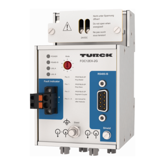
FOC12EX- 2G: 1 × RS485-IS and 2 × FO op is, suitable for use in Zone 2 Device overview 91.6 [3.61] 105.4 [4.15] [0.35] 10.3 65.1 [2.56] 73.5 [2.89] [0.40] mm [Inch] Fig. 1: FOC1… – Dimensions Hans Turck GmbH & Co. KG | T +49 208 4952-0 | F +49 208 4952-264 | more@turck.com | www.turck.com... -
Page 9: Properties And Features
Fig. 2: FOC1… – Connections and operating elements Position Description Power supply connection IP30 cover Rotary switch: Baud rate/operating mode FOC1…-3G: RS485 interface FOC1…-2G: RS485-IS interface RS485 shield: Screw head connected to M5 × 1 bolt (shield) – capacit- ively with insulating washer, directly without insulating washer FO interface, BFOC/2,5 (ST) connector RS485 shield: M5 ×... - Page 10 2 × intrinsically safe FO interface (Ex op is) 1 × NAMUR alarm output Applications: FO point-to-point connection, FO ring Hans Turck GmbH & Co. KG | T +49 208 4952-0 | F +49 208 4952-264 | more@turck.com | www.turck.com...
-
Page 11: Functions And Operating Modes
Functions and operating modes Media converter The media converter is supplied with 24 VDC in accordance with explosion protection type Ex e. The RS485 interface enables up to 31 nodes (e.g. excom stations) to be connected. The FO me- dia converter is a physical station and must be included as a bus device within a PROFIBUS seg- ment. - Page 12 FOC11EX-2G RS485 RS485-IS PORT PORT TX RX TX RX FO is op Fig. 3: FOC media converters – single point-to-point connection Hans Turck GmbH & Co. KG | T +49 208 4952-0 | F +49 208 4952-264 | more@turck.com | www.turck.com...
- Page 13 FO point-to-point connections – cascaded Several FO media converters can be connected in series (cascaded) in order to lengthen FO seg- ments. Depending on the application, a cascaded point-to-point connection is implemented with the following FOC11 and FOC12 media converters: The FOC11-3G and FOC12-3G media converters are used to connect to the non-intrinsically safe RS485 interface.
- Page 14 TX RX TX RX TX RX TX RX TX RX TX RX Fig. 5: FOC media converters – cascaded point-to-point connection Hans Turck GmbH & Co. KG | T +49 208 4952-0 | F +49 208 4952-264 | more@turck.com | www.turck.com...
- Page 15 FO ring ─ with PROFIBUS-DP Depending on the application, an optical ring can be implemented in an FO network with PROFIBUS-DP – using the following FOC12 media converters: The FOC12-3G media converters are used to connect to the non-intrinsically safe RS485 in- terface.
- Page 16 The FOC12 media converters can be replaced during opera- tion without interrupting communication or added in order to extend the FO ring. Hans Turck GmbH & Co. KG | T +49 208 4952-0 | F +49 208 4952-264 | more@turck.com | www.turck.com...
-
Page 17: Installing
Installing The FOC11-3G and FOC12-3G media converters can be installed as equipment in the safe area and in Zones 2/22. For operation in Zone 2, install the devices in an approved Ex e housing in accordance with EN 60079-0 with a protection type of at least IP54. Operation in Zone 22 re- quires installation in a housing in accordance with EN 60079-31. -
Page 18: Connection
FO interface, BFOC/2,5 (ST) connector RS485 shield: M5 × 1-bolt (shield) Alarm output LED indicators Housing potential: M5 × 1 bolt (case ground) Hans Turck GmbH & Co. KG | T +49 208 4952-0 | F +49 208 4952-264 | more@turck.com | www.turck.com... - Page 19 Wiring diagrams Port A RS485 RS485 Port A YE/RD YE/RD Port A Port A Port B YE/RD YE/RD Port B YE/RD – – RS485 RS485 24 VDC 24 VDC – – shield shield case ground case ground Fig. 9: FOC11-3G – wiring diagram Fig. 10: FOC12-3G –...
- Page 20 If the shield is to be connected to the case ground housing potential: Connect the M5 × 1 bolt (shield) with the M5 × 1 bolt (case ground). Hans Turck GmbH & Co. KG | T +49 208 4952-0 | F +49 208 4952-264 | more@turck.com | www.turck.com...
- Page 21 FOC11…- 3G and FOC12…- 3G: Connecting media converters to the fieldbus The fieldbus interface is provided with a 9-pin SUB-D female connector. „ Connect the device as per the wiring diagram via a standard PROFIBUS SUB-D male con- nector (e.g. D9T-RS485, ID 6890942) to the fieldbus master or fieldbus station. Fig. 13: SUB-D female connector Assignment of SUB-D pins Pin No.
- Page 22 Connect the TxD terminal (transmitter) of device 1 to the RxD terminal (receiver) of device 2. „ Connect the RxD terminal (receiver) of device 1 to the TxD terminal (transmitter) of device 2. Hans Turck GmbH & Co. KG | T +49 208 4952-0 | F +49 208 4952-264 | more@turck.com | www.turck.com...
- Page 23 Connecting FOC12 media converters in the ring (PROFIBUS-DP) Two independent optical rings are set up via port A and port B. „ Connect the TxD terminal of one device with the RxD terminal of the other device so that a closed ring is produced. PROFIBUS- DP Master PROFIBUS-DP...
- Page 24 FOC1…EX-2G: Bus termination on the intrinsically safe side is in accordance with the RS485-IS guidelines (Doc. no. 2.262) of the PROFIBUS User Organisation (PNO). Hans Turck GmbH & Co. KG | T +49 208 4952-0 | F +49 208 4952-264 | more@turck.com | www.turck.com...
-
Page 25: Commissioning
Commissioning DANGER Potentially explosive atmosphere Risk of explosion through spark ignition „ Use in Zones 1 and Zone 2: Only operate the device with an enclosed IP30 cover via the connection terminals The device is operational automatically once the cables are connected and the power supply is switched on. -
Page 26: Operation
Communication error Port B No bus communication (only FOC12) Yellow Bus communication active Red flashing Telegrams currently faulty Communication error Hans Turck GmbH & Co. KG | T +49 208 4952-0 | F +49 208 4952-264 | more@turck.com | www.turck.com... -
Page 27: Setting
Setting Transfer rate (rotary switch) The transfer rate with PROFIBUS-DP is detected automatically by the device. For other byte-ori- ented serial data streams, the transfer rate must be permanently set via a rotary switch (posi- tion 3…9). The data bytes have the following structure: 1 start bit/8 data bits/even parity/1 stop bit. -
Page 28: Bus Parameters
Baud rate max T in t SDR def Baud rate ≤ 187.5 k Baud rate 500 k Baud rate 1.5 M Hans Turck GmbH & Co. KG | T +49 208 4952-0 | F +49 208 4952-264 | more@turck.com | www.turck.com... - Page 29 FO point-to-point connection – calculation of T (examples) slot Example 1: PROFIBUS- DP Master PROFIBUS-DP Nodes (max. 31) FOC11-3G FOC11-3G RS485 RS485 PORT PORT TX RX TX RX FO is op PROFIBUS-DP Nodes (max. 31) FOC11-3G FOC11EX-2G RS485 RS485-IS PORT PORT TX RX TX RX...
- Page 30 ≥ 33 × N + 150 t = 282 t ≥ max T + 15 t = 297 t slot Hans Turck GmbH & Co. KG | T +49 208 4952-0 | F +49 208 4952-264 | more@turck.com | www.turck.com...
- Page 31 FO ring – calculation of bus parameters A bit time of 44 t must be taken into account for the transfer between two FOC media con- verters in an FO ring. Added to this is a one-off value of 33 t .
- Page 32 ≥ (44 × (N - 1) + 33) × 2 + 150 t = 568 t ≥ max T + 15 t = 583 t slot Hans Turck GmbH & Co. KG | T +49 208 4952-0 | F +49 208 4952-264 | more@turck.com | www.turck.com...
- Page 33 Example 2 PROFIBUS-DP Nodes (max. 31) PROFIBUS- DP Master FOC11-3G FOC11EX-2G RS485 RS485-IS PORT PORT TX RX TX RX PROFIBUS-DP PROFIBUS-DP PROFIBUS-DP Nodes (max. 31) Nodes (max. 31) Nodes (max. 31) FOC12-3G FOC12-3G FOC12EX-2G FOC12EX-2G FOC12-3G RS485 RS485 RS485-IS RS485-IS RS485 PORT PORT...
-
Page 34: Troubleshooting
If there are no faults, there is a device malfunction. In this case, decommission the device and replace it with a new device of the same type. Hans Turck GmbH & Co. KG | T +49 208 4952-0 | F +49 208 4952-264 | more@turck.com | www.turck.com... -
Page 35: Maintenance
Turck. 12.1 Returning devices Returns to Turck can only be accepted if the device has been equipped with a Decontamination declaration enclosed. The decontamination declaration can be downloaded from https://www.turck.de/en/retoure-service-6079.php and must be completely filled in, and affixed securely and weather-proof to the outside of the packaging. -
Page 36: Technical Data
71 years acc. to SN 29500 (Ed. 99) 40 °C 40 °C Dimensions (W × H × D) 65 × 105 x 73.5 mm Hans Turck GmbH & Co. KG | T +49 208 4952-0 | F +49 208 4952-264 | more@turck.com | www.turck.com... -
Page 37: Technical Data - Foc1
14.2 Technical data – FOC1-…-3G Type code FOC11-3G FOC12-3G Ident No. 100000549 100000553 Rated voltage 24 VDC Supply voltage range 18…32 VDC Inrush current < 100 mA Power consumption Typically 2.4 W Heat dissipation max. 32 W Galvanic isolation Complete galvanic isolation in accordance with IEC/EN 60079-11 (bus to bus and bus to power supply), rated voltage 250 V, test voltage 600 V Number of channels... -
Page 38: Approvals And Device Markings
≤ 4.2 V = 35.7 µF negligible Optical interface Ex op is Alarm output ≤ 10 V = 30 nF negligible Hans Turck GmbH & Co. KG | T +49 208 4952-0 | F +49 208 4952-264 | more@turck.com | www.turck.com... -
Page 39: Foc1
15.2 FOC1…-3G – approvals and device markings Approvals Marking as per ATEX directive EN 60079-0/-7 /-11 /-18 / -28 ÉII 3 (1) G ATEX approval no.: Ex ec mc ic [op is Ga] IIC T4 Gc ÉII (1) D EPS 21 ATEX 1 058 X [Ex op is Da] IIIC IECEx approval no.: Ex ec mc ic [op is Ga] IIC T4 Gc... -
Page 40: Turck Subsidiaries - Contact Information
Turck Comercial, S. de RL de CV Mexico Blvd. Campestre No. 100, Parque Industrial SERVER, C.P. 25350 Arteaga, Coahuila www.turck.com.mx Hans Turck GmbH & Co. KG | T +49 208 4952-0 | F +49 208 4952-264 | more@turck.com | www.turck.com... - Page 41 Turck Sweden Office Sweden Fabriksstråket 9, 433 76 Jonsered www.turck.se Singapore TURCK BANNER Singapore Pte. Ltd. 25 International Business Park, #04-75/77 (West Wing) German Centre, 609916 Singapore www.turckbanner.sg Turck Banner (Pty) Ltd South Africa Boeing Road East, Bedfordview, ZA-2007 Johannesburg www.turckbanner.co.za...
- Page 42 Over 30 subsidiaries and over 60 representations worldwide! 100030776 | 2021/12 100030776 www.turck.com...
Need help?
Do you have a question about the FOC1 Series and is the answer not in the manual?
Questions and answers