Bluetti EP600 Quick Manual
Hide thumbs
Also See for EP600:
- Quick start manual ,
- Installation manual (113 pages) ,
- User manual (88 pages)
Table of Contents
Advertisement
Quick Links
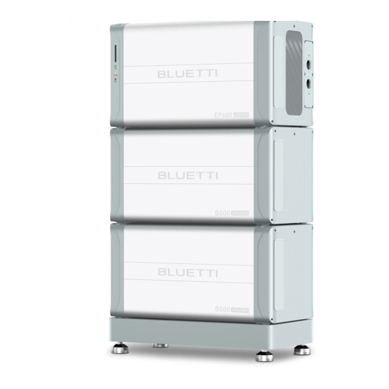
1. Overview
EP600
1
PV input 1
2
PV input 2
3
DC ON/OFF
Battery
4
Negative
B500
1
Negative output cable port
(Upper)
2
Signal connection cable port
(Upper)
3
Signal cable port (Bottom)
4
Negative output cable port
(Bottom)
5
Manual mechanical switch
2. Installation
2.1 overview
NOTE: The Meter is only used for the situation of installed three phase solar PV inverters, it is provided By BLUETTI and it
is free.
NOTES:
1. This document is for quick guidance installation only. For details, please refer to the installation and User Manual.
2. Machine damage caused by failure to follow the content is not covered by the warranty.
EP600 Quick Guide
Waterproof and
5 LED Indicator 9
13
ventilate valve
COM
6 Signal Port 1 10
14
Communicate Port
7 Signal Port 2 11
CT Input Port
15
Battery
8
12
DRMs Port
16
Positive
6 Positive output cable
11
Ground wire
port (upper)
port(Upper)
7
Inverter signal cable
12
Ground wire
port
port(Bottom)
Waterproof and
13
Waterproof and
8
breathable valve
breathable valve
9
Positive output cable port (bottom)
10
ON/OFF Switch
2. Installation
2.2 Installation requirements
USB Port
Load Port
Grid Port
Ground
3. Connecting cables
3.1 overview
2. 3 Wall mounting
3.2 Connect the communication cable
Note:Make sure the router used for EP600 applies to WiFi of
IEEE 802.11 b/g/n, 2.4GHz, please turn off the 5G option
Advertisement
Table of Contents

Subscribe to Our Youtube Channel
Related Manuals for Bluetti EP600


Summary of Contents for Bluetti EP600
- Page 1 ON/OFF Switch 2. Installation 2.1 overview NOTE: The Meter is only used for the situation of installed three phase solar PV inverters, it is provided By BLUETTI and it is free. NOTES: Note:Make sure the router used for EP600 applies to WiFi of 1.
- Page 2 2.Pay attention to the phase sequence when connect the CT: L1 to R, L2 to S, L3 to T. 3.The CT connect to the EP600 must be installed onto the L1/L2/L3 cables of the residential main circuit breaker. 3.7 Connection Transfer Switch Transfer switch is necessary for building a partial residential backup system.
- Page 3 DC circuit breakers on EP600. Step5: Switch on the AC circuit breakers connected to the EP600 grid port. Step6: Power on the system via the BLUETTI app. For details, please refer to Setting section on App Manual. Step7: Check the voltage of BACKUP.
Need help?
Do you have a question about the EP600 and is the answer not in the manual?
Questions and answers