
Related Manuals for Bluetti EP760


Summary of Contents for Bluetti EP760
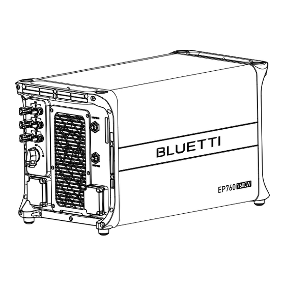
- Page 1 EP760 Energy Storage System User Manual Please Read This Manual Before Use And Follow Its Guidance. Keep This Manual For Future Reference.
- Page 2 Thank You! Thank you for making BLUETTI a part of your family. From the very beginning, BLUETTI has tried to stay true to a sustainable future through green energy storage solutions for both indoor and outdoor use while delivering an exceptional eco-friendly experience for our homes and our world.
- Page 3 Shenzhen PowerOak Newener Co., Ltd. Notice BLUETTI's products, services, and features are subject to the agreed-upon terms and conditions during purchase. Please note that some products, services, or features described in this manual may not be available under your purchase contract.
- Page 4 About the Manual Purpose This user manual describes the installation, electrical connection, commission- ing, maintenance and troubleshooting of EP760 energy storage system. Please read and understand all instructions in this manual before use. Target Audience • Installation, operation, and maintenance technicians •...
-
Page 5: Table Of Contents
Contents Safety Guideline EP760 Energy Storage System Introduction Working mode EP760 Inverter Features Inverter Overview Inverter Interface LED Indicator Buzzer Alarm Inverter Cables B500 Battery Features Battery Overview Battery Interface LED Indicators Battery Cables IoT Controller Communication Principle Overview Safety Instructions... -
Page 6: Safety Guideline
The Safety Requirements provided herein are for illustrative purposes that include but are not limited to those listed in this manual. Actual operation shall comply with all applicable safety standards. If you have any questions, feel free to contact BLUETTI support or your local BLUETTI dealers. - Page 7 • If the equipment’s shell is cracked during transportation or use, do not use it and contact BLUETTI support or your local BLUETTI dealers. • Use a dry powder fire extinguisher if the equipment catches fire. •...
- Page 8 • Turn off the equipment IMMEDIATELY in case of malfunction, and contact the BLUETTI support team if this manual cannot explain the malfunction adequately to you. • Do not place the equipment on unstable or inclined surfaces. Keep away from children and pets.
- Page 9 Keep the system firmly secured to the ground or other solid objects, such as a wall or mounting bracket. • Use a non-abrasive cloth to clean the equipment and accessories. Do not use water or harsh chemicals. • Please follow the instructions to install the EP760 energy storage system. JUST POWER ON...
- Page 10 1.3 Battery Safety 1.3.1 Statement BLUETTI shall not be liable for equipment abnormality component damage, personal injury property loss or other damage caused by the following reasons: • Failure to promptly charge the battery after installation and system connection, leading to over-discharge and subsequent damage.
- Page 11 • Battery damage caused by operating conditions or external power parameters that do not meet environmental requirements, including situations where the working tempera- tures are excessively high or low, or when the power grid experiences frequent interrup- tions or outages. 1.3.2 General Requirements •...
- Page 12 (b)Eye Contact: Immediately flush eyes with water for at least 15 minutes, do not rub eyes, and seek medical attention immediately. (c)Skin Contact: Immediately wash the infected area with soap and water and seek medical attention immediately. (d)Ingestion: Seek medical attention immediately. •...
- Page 13 If the battery is obviously damaged or there is an abnormal smell, smoke or fire, please evacuate immediately, and contact a profes- sional or BLUETTI support. Professionals can use fire extinguishing facilities to extinguish the fire under safety protection. Fig. 1-1 1.3.4 Battery Disposal...
- Page 14 • Make sure that all electrical connections comply with your local electrical standards. • Before connecting an EP760 energy storage system to your home grid, consult your national or regional electricity authority for guidance. • User-prepared cables should adhere to local laws and regulations.
- Page 15 1.5 Maintenance Requirements Danger The equipment generates high voltage during operation, which can cause electric shock leading to severe injury, property damage, or even death. Please strictly follow the safety instructions provided in the user manual and adhere to relevant electrical safety codes. To ensure your safety while maintaining the system, please follow the following steps: Step1: Disconnect the power grid.
- Page 16 1.6 Transportation Requirements All components of the EP760 energy storage system leave the factory in optimum electrical and mechanical state. It's necessary to use original or appropriate packaging to ensure the product safety during transportation. When you receive the product, inspect for any kind of damage and note the damage on the delivery receipt.
- Page 17 1.9 Label Description Table 1-2 Labels and Description Label Name Description There is still residual voltage after the equipment is powered off. Please wait Discharge delay at least 5 minutes until the equipment is discharged. The system generates high voltage during operation.
-
Page 18: Ep760 Energy Storage System
2. EP760 Energy Storage System 2.1 Introduction The BLUETTI EP760 is a formidable home energy storage system (ESS) built to provide a robust power solution for your household and light commercial needs. With a remarkable output of 7,600W, the EP760 offers a substantial power supply that can be further customized by connecting LiFePO4 batteries, allowing you to tailor its capacity according to your specific requirements. -
Page 19: Working Mode
• Mode 1 If there is already a grid-connected PV system, combine it with the EP760 ESS by means of AC coupling. This setup prioritizes PV power for the load, charges the batteries with excess power, and feeds surplus energy back to the grid. - Page 20 In the absence of a PV system, the load is powered by the backup battery. When the battery charge is depleted, the system automatically switches to grid power to continue supplying the load. Grid AC loads Solar panels EP760 Green Energy Public Grid Energy B500 Hybrid Energy BLUETTI APP Figure 2-3 •...
- Page 21 • Mode 4 The batteries are charged from the grid, and the BLUETTI App gives you the flexibility to set the charging time and power to suit your needs. Grid AC loads EP760 Green Energy Public Grid Energy Hybrid Energy...
-
Page 22: Ep760 Inverter
3. EP760 Inverter EP760 inverter is an energy storage photovoltaic grid-connected inverter that can handle photovoltaic input, grid-connected charging, and discharging. It is an important part of the energy storage system. 3.1 Features Solar Energy Optimization: Triple MPPT charge controllers to maximize solar input, while storing solar energy in LiFePO4 batteries. -
Page 23: Inverter Interface
3.2.2 EP760 Inverter Dimensions Table 3-2 (Unit:mm) 626mm 324mm Front Right 3.3. Inverter Interface 3.3.1.EP760 Interface Table 3-3 Left Right Name Name Name PV Input 1 LINK PORT 1 DRMs Port (Generator) PV Input 2 LINK PORT 2 USB Port... - Page 24 3.3.2 Interface Description Table 3-4 Type of Cable Terminal Cable specification Description Required BAT+: to the Battery expansion battery BAT+ terminal cable (Positive) BAT-: to the Battery expansion battery BAT- terminal cable (Negative) PV1+: to the positive terminal of solar panel Outdoor multi-core Conductor PV1-: to the negative...
- Page 25 The USB drive should be formatted as FAT32 with no more than 32G in size. 3.3.4 DRMs Port The EP760 ESS offers the flexibility to be upgraded for solar energy storage, allowing you to harness more power from the sun. Additionally, it features a DRM interface specifically designed to serve as a convenient ignition reserve port for diesel...
-
Page 26: Led Indicator
3.3.5. LINK PORT 1 & LINK PORT 2 Table 3-6 Interface Function Note Link Port 1 Connect the IoT controller Refer to Fig. 6-7 for details. Link Port 2 Connect the battery pack 3.3.6. CT Port Table 3-7 Definition Description Note CT-L1+ (Red) CT output positive terminal... -
Page 27: Buzzer Alarm
When a fault occurs, the buzzer emits a series of 5 beeps. Each time lasts for 2 seconds with a 1-second interval between each beep. Note: The buzzer alarm can be turned off in the BLUETTI App. Table 3-10 Fault Code... -
Page 28: B500 Battery
The B500 battery energy storage system is designed for residential and light commercial use. Single B500 battery pack has a capacity of 4.96kWh. BLUETTI EP760 ESS supports 4 *B500 units for a whopping 19.84kWh, enough to power a house for several days. -
Page 29: Battery Interface
4.3 Battery Interface 4.3.1. B500 Interface Table 4-2 Left Right Name Name BAT- terminal 1 Bleed valve 1 Pack link-in BAT+ terminal 2 Pack link-out Power button BAT- terminal 2 Grounding port 1 Main switch Grounding port 2 BAT+ terminal 1 Bleed valve 2 Inverter signal port (TO Pcs) -
Page 30: Led Indicators
⑦ Inverter signal For communication between inverter and battery packs. Connect to the port(PCS LINK) LINK PORT 2 of EP760 inverter via the battery communication cable. ②Battery pack For communication between battery packs. Connect to the battery pack signal output port of the upper battery via the communication signal input port cable when multiple B500s are stacked. -
Page 31: Battery Cables
4.5 Battery Cables Table 4-6 Battery Cables Picture Description Interface (connect to) LINK PORT 2 of Communication Cable the inverter Red battery expansion cable (Positive) BAT+ terminal 2 Black battery expansion cable (Negative) BAT- terminal 2 Grounding Cable Grounding port JUST POWER ON... -
Page 32: Iot Controller
BLUETTI server via the WiFi network. By registering the EP760 ESS with your BLUETTI account, you’re able to monitor and control this unparalleled power plant anytime and anywhere. -
Page 33: Safety Instructions
5.3 Safety Instructions • The IoT controller is ONLY applicable to BLUETTI products. • Do not keep the controller near heat sources or in high temperatures. • Do not store the controller with flammable liquids, gases, or explosive materials. •... - Page 34 Step2: Turn on EP760, and the IoT controller starts up automatically. Step3: Configure the controller in BLUETTI App. • Scan the QR code below to download the BLUETTI App, or search for “BLUETTI” in the App Store/Google Play. • The BLUETTI App connects to EP760 ESS via Bluetooth or WiFi. Tap “LOGIN/REGIS- TER”...
- Page 35 • Check your email for verification code from BLUETTI server, and fill in the code to activate your BLUETTI account. Instruction Firewall Settings When EP760 ESS is connected to a network with firewall for outbound communication, set permission to access port 18760 as follows.
-
Page 36: System Installation
6. System Installation Danger Before installation, disconnect all circuit breakers for the battery pack, solar system, and the main switch of the grid to ensure safe operations. 6.1 Installation Procedure Start Preparation Stacking the batteries Installing the inverter Installing the IoT controller Electrical Connection System Check JUST POWER ON... -
Page 37: Installation Preparation
6.2. Installation Preparation 6.2.1. Packing Lists Upon receiving the package, we kindly ask you to carefully inspect and verify the presence of all components and accessories included. EP760 Inverter Packing List Table 6-1 Picture Description Qty. EP760 inverter Bracket #1... - Page 38 6 for AC cable protection case, pre-installed on EP760 inverter) M8*12 screw (For battery power cable) M6*12 screw (For bracket, pre-installed on EP760 inverter) M5*10 screw (4 for fixing device to the bracket, 2 for PV grounding) M4*10 screw (For exterior trim) M8*60 expansion bolt Self-tapping screw, ST8×40...
- Page 39 Red battery power cable (Positive) Black battery power cable (Negative) IoT Controller Mounting bracket (IoT controller) Expansion wall plug M3 tapping screw (KA3*25) CT communication cable (4m) M16 3-pin adapter JUST POWER ON...
- Page 40 B500 Battery Packing List Table 6-2 Picture Description Qty. B500 Battery Module Bracket #1 Bracket #2 M5 hex nut Left cover Right cover M4*8 screw (for fastening covers) M5*10 screw (for brackets) Communication cable Red battery expansion cable (Positive) JUST POWER ON...
- Page 41 Black battery expansion cable (Negative) Grounding cable M8*60 expansion bolt (for brackets) Self-tapping screw, ST8×40 M6*12 screw (Grounding cable) Spare screw kit 6.2.2 Base Packing List Table 6-3 Base Packing List Picture Description Quantity Base JUST POWER ON...
- Page 42 6.2.3 Required Tools Table 6-4 Required Tools Picture Description Electric drill (5/8/10mm) Socket wrench set Torque wrench Flat screwdriver Cross screwdriver (4mm) MC4 spanner Cable cutter Cable stripper Cable Crimper Multimeter (DC voltage ≥ 1000VDC) JUST POWER ON...
- Page 43 Marker Measuring tape Level ruler Box cutter Heat shrink tubing Heat gun Cable tie Anti-static gloves Protective goggle Mask Safety-toe shoes JUST POWER ON...
-
Page 44: Installation Requirements
Vacuum cleaner 6.3 Installation Requirements 6.3.1 Environment Requirements • Install the EP760 ESS in a well-ventilated and spacious area to ensure good heat dissipation. • The EP760 ESS has an IP65 rating and can be installed indoors and outdoors. Please note that if you place the system outside the house, use a cabinet to protect it from direct sunlight, as this may cause a degradation in system performance. - Page 45 Danger 6.3.2 Location Requirements • The EP760 ESS should be installed on a firm, flat, level base. • Do not install the system on flammable materials. • Consider the weight and placement of components to ensure adequate structural support.
-
Page 46: Stacking The Ep760 Ess
Ø8 Figure 6-3 (Unit: mm) 6.4 Stacking the EP760 ESS Step 1: Place the base on the ground and adjust the height of leveling feet so that the base stands stably on the ground. Don’t forget to tighten the nuts to secure the leveling feet. -
Page 47: Iot Controller Installation
#1 and M8 expansion bolts. Secure the connection with M8 and M5 nuts. Step 5: Repeat Step3 and 4 to secure all battery packs. Step 6: Follow the same steps to install the EP760 inverter on top. EP760 Wall... - Page 48 24mm 2- 5.0 Fig. 6-6-1 Fig. 6-6-2 Bracket Expansion Wall Plug Self-tapping Screw Fig. 6-6-3 Fig. 6-6-4 Controller Fig. 6-6-5 Fig. 6-6-6 Figure 6-6 JUST POWER ON...
-
Page 49: Electrical Connection
6.6 Electrical Connection 6.6.1 Cables Table 6-5 Cables Picture Cable Red battery power cable (Positive) Black battery power cable (Negative) CT communication cable Communication cable Red battery expansion cable (Positive) Black battery expansion cable (Negative) Grounding cable Outdoor multi-core copper cable COM communication cable JUST POWER ON... - Page 50 6.6.2 Connection Procedure Connect Battery Power Cables Connect Communication Cables Start Connect Grounding Cables Connect PV cables Connect GRID and BACKUP Cables Connect CT Figure 6-7 JUST POWER ON...
- Page 51 Figure 6-8 JUST POWER ON...
- Page 52 See “①” “②” of Figure 6-9-1 and 6-9-2. Step 2:Connect the top B500 to EP760 inverter via the battery power cables - black cable for negative terminals, red for positive terminals. See “③” “④” of Figure 6-9-1 and 6-9-2.
- Page 53 Figure 6-9-2 Figure 6-9-2 Figure 6-9-2 Figure 6-9-2 JUST POWER ON...
- Page 54 Max. Torque: 6Nm Max. Torque: 1.2Nm 1. Inverter BAT- terminal (Black) 2. Black battery power cable (BAT-) 3. M8*12 screws 4. Black protection cover (BAT-) Figure 6-9-3 5. M4*12 screws Max. Torque: 6Nm Max. Torque: 1.2Nm 1. Inverter BAT+ terminal (Red) 2.
- Page 55 LINK PORT 2 of EP760 inverter. See Figure 6-10 “②”. Step 3: Connect the IoT controller to the EP760 inverter. See Figure 6-10 “③”. Note: For how to integrate multiple B500s to the EP760 ESS, please refer to Figure 6-8. IoT Controller Figure 6-10...
- Page 56 6.6.5 Connect Grounding Cables Danger The positive and negative terminals of the PV (photovoltaic) system inverter should not be grounded, as it may lead to inverter failure. However, it is important to ground all non-current carrying metal parts, including brackets, distribution boxes, inverter enclosures, battery pack enclosures, and other relevant components.
- Page 57 L2=L1+3mm Terminal block L2 is 3mm longer than L1 Wire 6-11-1 L4≥1mm Visible wire Qualified L3≥2mm Wire even or bulge up to 1mm 6-11-2 6-11-3 1 . M5×10 screws 2. OT terminal 3. PV grounding pole Figure 6-11-3 Grounding Connection JUST POWER ON...
- Page 58 6.6.6. Connect PV Cables Attention Before removing the PV input positive and negative connectors, make sure the DC switch on the EP760 inverter has been set to “OFF”. Step 1: It is recommended to use a 2.5mm outdoor power cable. Disconnect the cable connector from the EP760 positive and negative connectors.
- Page 59 MC4 Wrench 1. Positive metal terminal 2. Negative metal terminal Figure 6-12-3 Figure 6-12-4 Figure 6-12-5 Figure 6-12-6 Remove the PV connector Figure 6-12-7 Figure 6-12 JUST POWER ON...
- Page 60 Figure 6-13-2. Then, pull to confirm that the terminal crimping is tight. Step 3: Fix the terminals to EP760 inverter BACKUP and GRID areas with a cross screwdriver as shown in Figure 6-13-3 and 6-13-4. Step 4: Attach the PG waterproof connector to the AC cable protection case. Tighten the hexagon nut of the connector with a socket tool, as shown in Figure 6-13-5.
- Page 61 M6 Screws M6 Screws Max. Torque: 3.0Nm Max. Torque: 3.0Nm Figure 6-13-3 Figure 6-13-4 AC cable protection case PG waterproof connector PG waterproof connector AC cable protection case Figure 6-13-5 Figure 6-13-6 hexagon nut PG waterproof connector 1M4*12 screw, (MAX. Torque: 1.2Nm) BACKUP cables &...
- Page 62 6.6.8. CT Step 1: Rotate the CT adapter cap counterclockwise and take it off, and tighten the screws of the connector with a screwdriver. Note: Insert the red signal cable into the L phase, and the black signal cable into the N phase.
- Page 63 The arrow points to the grid. GRID-L Figure 6-14 Follow the diagram below for the correct CT direction from the grid-tie inverter to the grid. Backup Loads Non-essential Loads N PE EP760 Transfer Switch Main Breaker Solar On_Grid Breaker CT-1 B500 Figure 6-15 DC Coupling...
-
Page 64: System Check
Backup Loads Loads N PE 21 22 Meter Transfer Switch CT-1 Solar Main Breaker EP760 On_Grid Breaker CT-1 B500 Figure 6-16 AC Coupling 7. System Check 7.1 Preliminary Check Check the followings before first use. • Confirm that all components of the system are installed according to specific requirements. - Page 65 Step 3: Wait for about 40 seconds till the inverter indicator keeps steady green. Step 4: Switch on the AC circuit breakers connected to the inverter GRID terminal. Step 5: Power on the system via BLUETTI App. For details, please refer to BLUETTI App Instructions.
-
Page 66: System Maintenance
USB drive, or EP760 will report a USB Format Error. Step 7: Pair EP760 ESS with BLUETTI App, then you can check the firmware version in System information>> Firmware version. If any of the following occurs, please try the solutions provided. -
Page 67: System Disposal
AC input cable, grounding cable, etc. Step 3: Remove the inverter and related parts. 9.2 Recycle the EP760 Inverter and B500 Battery Pack When the battery pack reaches the end of its lifespan, it must be safely and carefully disposed of by the provisions of local laws and regulations. -
Page 68: Specifications
10. Specifications 10.1. AC Interface AC (Grid-tied) Item Description Rated Output Power 7.6kW (4.6kW in Germany) Output Apparent Power 7.6kVA (4.6kVA in Germany) Wiring L/N/PE Rated Voltage 230V Voltage Range 185V~285VAC Maximum Output Current 33A (20A in Germany) Input Frequency 50Hz Frequency Range 47.5Hz~51.5Hz... - Page 69 AC (Off-Grid) Item Description Rated Output Power 7.6kVA Output Voltage 230V Output Current Output Frequency 50Hz Inversion Efficiency 94.5% Peak Output Voltage THD <3%, pure resistive load 100%-110% of rated power, 10min; Overload 110%-150% of rated power, 10s. Output overcurrent protection Protection Short-circuit protection Over temperature protection...
- Page 70 10.2. DC Interface PV Input Item Description Maximum Input Power 9kW (3kW for each channel) MPPT Channel Array in Series Maximum Input Voltage 550V MPPT Voltage Range/Rated 150V~500V/360V Single MPPT Maximum Input Current 12.5A Single MPPT Maximum Short-circuit Current MPPT Efficiency 99.9% PV Inversion Efficiency 96.0% Max.
- Page 71 10.3. General AC (Grid-tied) Item Description Relative Humidity 5%-95% Standby Power Operating Temperature -20℃~40℃ Noise ≤50dB (A) Cooling Forced air cooling Protection Grade IP65 Working Altitude ≤2000m Dimensions (L*W*H) 626mm×324mm×368mm Net Weight 44kg Communication USB / WiFi / Bluetooth Warranty 10 years 10.4.
-
Page 72: Troubleshooting
Hardware BUS2 Overvoltage Hardware Battery Overvoltage Turn off the inverter and wait 30 minutes to restart it. If the symptom persists, Hardware Inverter Overcurrent please contact the BLUETTI support team. Reserved Hardware LLC1 Input Overcurrent Reserved Reserved Auxiliary Power Undervoltage... - Page 73 Check if the inverter fan operates well. Turn off the inverter and wait 30 minutes Zero Drift Anomaly to restart it. If the symptom persists, please contact the BLUETTI support team. Hardware Input Overcurrent Check if the DC voltage is too low. DC Input Voltage Low...
- Page 74 Operating Ambient Temperature Anomaly Temperature 1 Anomaly Please make sure use the system within specific temperature range. If the symptom persists, Temperature 2 Anomaly please contact the BLUETTI support team. Temperature 3 Anomaly Temperature 4 Anomaly BMS Charge Protection BMS Discharge Protection Check the details on BLUETTI app.
- Page 75 BLUETTI support team. Check whether the meter is powered and whether the communication cable between 140. Meter Communication Failure the meter and the EP760 energy storage system is connected normally. If the problem persists, please contact technical support. Reserved 141.
-
Page 76: Faqs (Frequently Asked Questions)
The startup time may vary slightly depending on the startup method, but it should not exceed 3 minutes. Can I connect a solar system that exceeds the PV input limits of EP760 ESS? Will the EP760 ESS automatically adjust the input current? It depends on the voltage of your solar system. - Page 77 (3) With the same connector (MC4). Why isn't my solar system able to charge the EP760 ESS? (1) Make sure that the PV switch of the EP760 ESS is in the "ON" position. (2)Check the connections of the solar panel and the PV input cables.
- Page 79 For more information, please visit: @ BLUETTI Support @ BLUETTI Official @bluetti_official @ bluetti.inc @ bluetti_inc sale-eu@bluettipower.com sale-uk@bluettipower.com SHENZHEN POWEROAK NEWENER CO., LTD. Add: F19, BLD No.1, Kaidaer, Tongsha Rd No.168, Xili Street, Nanshan, Shenzhen, China After-sales address in EU: Lise-Meitner-Strasse 14, 28816 Stuhr, Germany After-sales address in UK: Unit 2 Northgate, Bolsover Busines Park, Woodhouse Line, Chesterfield England S44 6BD...
Need help?
Do you have a question about the EP760 and is the answer not in the manual?
Questions and answers