Bluetti EP600 User Manual
Energy storage system
Hide thumbs
Also See for EP600:
- Quick start manual ,
- Installation manual (113 pages) ,
- User manual (88 pages)
Table of Contents
Advertisement
Quick Links
Advertisement
Table of Contents

Related Manuals for Bluetti EP600


Summary of Contents for Bluetti EP600
- Page 1 EP600 Energy Storage System User Manual Shenzhen PowerOak Newener Co.,ltd...
- Page 2 This user's manual introduces the installation, electrical connection, debugging, maintenance and troubleshooting of EP600 energy storage system, and the tutorial of user operation interface. When installing and using the system, please read the manual carefully, understand it’s safety knowledge, and be familiar with it’s functions and characteristics.
- Page 3 EP600 Energy Storage System User Manual Danger It indicates that there is a high potential danger, it may cause death or serious injury if not avoided. Warning It indicates that there is a moderate potential danger, it may cause death or serious injury if not avoided.
-
Page 4: Table Of Contents
1.5 Box identification protection............................9 1.6 Storage instruction..............................9 2.1 EP600 energy storage system instruction........................ 10 2.2 Working mode................................11 3.1 The function and character of EP600 inverter......................13 3.2 Appearance instruction.............................13 3.3 LED Indicator.................................16 3.4 Buzzer Alarm................................16 3.5 Routine maintenance..............................17 4.1 B500 Product Information............................18... -
Page 5: Safety Instruction
The technician responsible for installing must hold an electrician certificate, because some components might electric charged or heat up when the EP600 energy storage system running, improper operation,incorrectly install or operate might cause the serious damage of personal safety andproperty. -
Page 6: Precaution Of Electrical Connection
The debris and dust should be cleaned out promptly after drilling. 1.3 Precaution of electrical connection The EP600 energy storage system will generate high voltage during operating, which may cause casualties, personal injury or serious damage to property. Please comply with relevant safety... - Page 7 Incorrect wiring may damage the Energy Storage System , such resulting damage will not within the warranty. Attention The EP600 energy storage system can be grid-connected for power generation only with the permission of the electricity power department of the country or region.
- Page 8 EP600 Energy Storage System User Manual Danger Before operating any maintenance, the electrical connection between the Energy Storage System and the grid must be disconnected first, then disconnect the electrical connection between inverter and PV、battery pack. Wait for at least 30 minutes until the internal components are discharge completely then the maintenance can be operated.
- Page 9 EP600 Energy Storage System User Manual operation. Please read the instruction carefully before operate the Read instruction Energy Storage System European standard CE This product comply with certification European standard CE certification. It must always be transported, handled and stored in this way...
-
Page 10: Precaution Of Transportation
The label shouldn't be covered, please clean up regularly. It should be always visible. 1.6 Storage instruction If the EP600 energy storage system isn’t put into use immediately, the storage shall meet the following requirements: Please power off the Energy Storage System and charge it to 50-70% of capacity before storage;... -
Page 11: Ep600 Energy Storage System Instruction
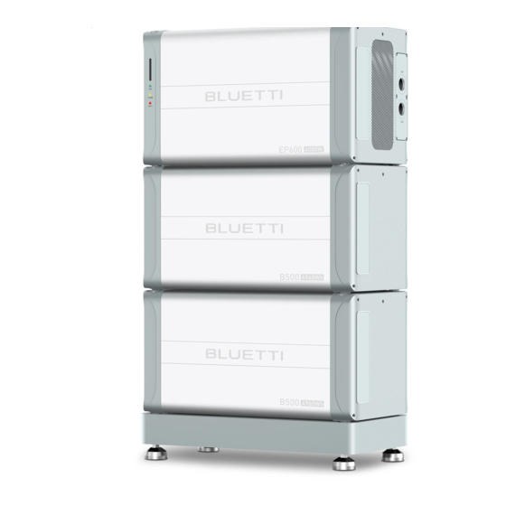
2. EP600 energy storage system 2.1 EP600 energy storage system instruction The EP600 energy storage system include grid-connected inverter (EP600) 、 energy storage battery pack (B500), IOT controller and other accessories (CT, cables, etc.), which can form a household energy storage and PV grid-connected power generation system with photovoltaic (PV) and user distribution box,etc;... -
Page 12: Working Mode
EP600 Energy Storage System User Manual 2.2 Working mode The following are the general working modes of the EP600 energy storage system. According to your configuration and layout condition to select the working mode. Mode1 PV generate power to the load , the overflow power will charge the battery first, then output to the grid;... - Page 13 EP600 Energy Storage System User Manual Mode3 When the power grid is cut off , PV and battery will provide power to the load together. Public Grid AC loads Solar panels EP600 Green Energy Public Grid Energy Hybrid Energy B500 battery...
-
Page 14: The Function And Character Of Ep600 Inverter
EP600 Energy Storage System User Manual EP600 Inverter instruction Ep600 inverter is a three-phase PV energy storage inverter integrate PV input and grid- connection charging and discharging. It is an important part of EP600 energy storage system. 3.1 The function and character of EP600 inverter PV application: Dual MPPT, which can achieve PV charge and storage energy, and also can generate power with grid-connected system . - Page 15 EP600 Energy Storage System User Manual EP600 Inverter port description Figure 3-2 Left Right Port name Port name PV input 1 Waterproof and ventilate valve PV input 2 COM Communicate Port DC ON/OFF CT Input Port Battery Negative DRMs Port...
- Page 16 EP600 Energy Storage System User Manual EP600 Inverter outline dimensions Figure 3-3(Unit:mm/in) Front Right...
-
Page 17: Led Indicator
EP600 Energy Storage System User Manual 3.3 LED Indicator Table 3-4 States Alarm Fault Green Orange Run Indicator light light light Alarm Indicator No alarm and Always Fault Indicator No fault Alarm without Flash Always fault No alarm with Alway... -
Page 18: Routine Maintenance
EP600 Energy Storage System User Manual 3.5 Routine maintenance EP600 inverter requires regular maintenance, details shown as follow: Check whether dust and other blockages are attached to the air outlet and the heat sink. If the fan is blocked or there is too much dust on the heat sink, clean the fan, fan guard or heat sink. -
Page 19: B500 Product Information
EP600 Energy Storage System User Manual 4. B500 Battery Pack Introduction 4.1 B500 Product Information The B500 energy storage battery system is designed for residential and small commercial uses. Single pack rated capacity is 4.96KWh. It support 16 battery packs in parallel to meet capacity up to 80KWH. - Page 20 EP600 Energy Storage System User Manual B500 Battery Pack Port Description Table 4-2 Left Right Parts name Parts name Negative output cable port Waterproof and breathable (Upper) valve Signal connection cable port Positive output port cable (Upper) bottom Signal cable port (Bottom)
- Page 21 EP600 Energy Storage System User Manual B500 Battery Pack Size Figure 4-3 (Unit :mm/in) Front Right...
-
Page 22: Indicator Descriptions
EP600 Energy Storage System User Manual 4.3Indicator Descriptions Light Status Meaning Remark B500 not start The circuit breaker can be operated now B500 is operating The circuit breaker can’t be operated 0.5Hz B500 is shutting The circuit breaker Flash down can’t be operated... -
Page 23: Ep600 Packing List
EP600 Energy Storage System User Manual 5. System Installation Danger During installation, make sure that the product has no electrical connection. Do not install the Energy Storage System near pipes, windows or other similar areas where water can leak easily to prevent liquids from entering and damaging the Energy Storage System. - Page 24 EP600 Energy Storage System User Manual PV decorative cover AC decorative cover (With label) Soft rubber stopper through the cable AC cable protection box 1.PV+ Input terminal plastic case 2.PV+ Input terminal metal core PV- Input terminal plastic case PV- Input terminal metal core...
- Page 25 EP600 Energy Storage System User Manual MC4 assemble and disassemble tool BAT- Input terminal plastic cover(Black) BAT+ Input terminal plastic cover(Red) M4*12 screw (8 fix BAT+/- terminal cover、 6 AC junction Box) M8*12 screw (Connect battery power cable) M6*12 screw(Fix bracket-wall screw)
- Page 26 EP600 Energy Storage System User Manual Battery power cable - IOT Controller Expandable rubber stopper M3 tapping screws(KA3*25) IOT Controller mounting bracket DRMs port connection cable CT port connection cable M20-6PIN adapter DRMs/CT adapter cable(1.5m) PG waterproof connector...
-
Page 27: B500 Packing List
EP600 Energy Storage System User Manual 5.2 B500 Packing List Table 5-2 Picture Description ntity B500 Battery Module Bracket 1 Bracket 2 M5 Hex Nut Left decorative cover Right decorative cover M4*8 screw M5*10 screw Battery positive expansion cable(Orange) - Page 28 EP600 Energy Storage System User Manual Battery negative expansion cable(Black) Communication cable Ground cable M8*60 Expansion bolt(Wall screw) M6*12 Ground cable screw Spare screws...
-
Page 29: Base List
EP600 Energy Storage System User Manual 5.3 Base List Table 5-3 Picture Description Quantity Base... -
Page 30: About Installation
EP600 Energy Storage System User Manual 5.4 About installation 5.4.1 Installation Environment Requirements Choose a dry, tidy place for easy installation The protection level of the inverter and battery pack is IP65, and can be installed both indoors ... - Page 31 EP600 储能系统用户手册 Picture 5-1 图 5-1 5.4.4 Space requirements for single system installation The following diagram shows the EP600 system installed in a single group. Wall Base Ground Figure 5-2 Ground,Base, Wall 5.4.5 Space requirements for multiple systems are installed side by side When multiple systems are installed side by side, keep at least 1000mm distance between them to reduce the impact of heat dissipation.
- Page 32 EP600 储能系统用户手册 Ground Table 5-3 ground...
- Page 33 EP600 Battery Energy Storage System User Manual 5.4.6 Size of base bracket installation Figure 5-4 5.4.7 Installation location requirements Danger Before drilling, please make sure to avoid the pre-buried water and electricity lines in the wall to avoid danger.
-
Page 34: Installation Tools
EP600 Battery Energy Storage System User Manual Project installation location Size of drilling the wall mounting holes (unit: mm): ( 3 layers) ( 4 layers) ( 5 layers) Ground Ground Ground Figure 5-5 Remarks: For system installation, a maximum of 5 layers of Energy Storage System (include inverter) are stacked on the base. - Page 35 EP600 Battery Energy Storage System User Manual Table 5-4 Tools Description Function Picture Electric drill machine requires 8mm drill Wall drilling Torque socket Remove and install screws wrench Torque wrench Remove and install screws Flat screwdriver Remove, install screws and...
- Page 36 EP600 Energy Storage System User Manual Crimp grid, critical load cable and CT extension Crimp tool cable Multimeter (DC voltage Check whether the cable range ≥ connection is correct, whether the positive and 1000V DC ) negative poles of the...
-
Page 37: Installation Steps
EP600 Energy Storage System User Manual Anti-static gloves Wear it when carrying and installing the machine Protective goggle Wear while drilling Face mask wear while drilling Safety shoes Wear it when carrying and installing the Energy Storage System Vacuum cleaner... - Page 38 EP600 Energy Storage System User Manual Step5 : Repeat Step3 and 4 , and fix the subsequent battery packs in turn. Step6 : Repeat Step3 and 4 to install the EP600 inverter on the top of the battery pack. Wall...
- Page 39 (such as inverters and battery systems ). Instruction The open circuit voltage of the PV modules connected to the EP600 cannot be more than 550V . The connected PV modules must have an IEC61730 class rating.
- Page 40 EP600 Energy Storage System User Manual 6.The whole units connection...
- Page 41 EP600 储能系统用户手册 Figure 6-1...
-
Page 42: B500 External Ports Description
EP600 Energy Storage System User Manual 6.2 B500 External ports description Table 6-2 Connect port name Connect port function Remark Inverter signal Used to connect the inverter, only the top battery pack needs connect port to connect inverter. ( PCS Link ) -
Page 43: Wiring Description Of Ep600 External Port
EP600 Energy Storage System User Manual Figure6-2 6.3 Wiring description of EP600 external port Figure 6-3 C a b l e i n s t r u c t i o n Port Define Cable type Cable specification Standard BAT+:Wire the battery... - Page 44 EP600 Energy Storage System User Manual BAT-:Wire the battery Standard negative accessories PV1+:To solar panel positive Outdoor PV1-:To solar panel multi-core negative copper core cable PV1 PE:PV1 to solar panel Conductor cross- ground sectional area PV2+:To solar panel 2.5mm ~4mm...
-
Page 45: Connection Ground Protection(Pe
The PV positive pole and negative pole of the inverter cannot be grounded, otherwise the inverter will fail. In EP600 energy storage system, all non-current carrying metal parts (such as bracket, distribution box, inverter shell, battery pack shell, etc.) should connect to the ground. -
Page 46: Connect Pv Cable
Attention Before removing the PV input positive and negative connectors, make sure the DCswitch on the EP600 inverter has been set to "OFF". Step 1: Select the appropriate cable type and specification according to table 6-3. Disconnect the cable connector from the positive and negative connector. - Page 47 EP600 Energy Storage System User Manual 1、Positive metal core Figure 6-4-2 2、Negative metal core Figure 6-4-1 Figure 6-4-6 Figure 6-4-5...
-
Page 48: Connect The Grid And Load Cable
EP600 Energy Storage System User Manual Remove the PV terminal with MC4 wrenchMC4扳手 拆下PV端子 Figure 6-4-7 6.6 Connect the grid and load cable Step 1: Select the appropriate cable type and specification according to figure 6-3; Strip the cable, For the stripping length, refer to figure 6-5-1. - Page 49 EP600 Energy Storage System User Manual Figure 6-5-4 Figure 6-5-3 Screws Max 1.2 N.m 1、AC cable 2、Protective cover of AC junction 1、Protective cover of AC junction box box3、M4×12 screws 2、M32 PG waterproof joint Figure 6-5-6 Figure 6-5-5...
-
Page 50: Connecting The Positive And Negative Poles Of The Battery
EP600 Energy Storage System User Manual Tighten the two PG waterproof joints, and the torque is recommended to be 3N.M Figure 6-5 Load cable connection 6.7 Connecting the positive and negative poles of the battery Step1: Remove the positive and negative protective cover of the inverter battery with a screwdriver(Figure 6- 6-1/6-6-2);... - Page 51 EP600 Energy Storage System User Manual 1、Battery negative terminal box(black BAT-) 2、Battery negative terminal box(black BAT-) 3、M8×12 screws 4、Battery negative terminal box protective cover(black BAT-) 6-6-3 5、M4×12 screws 1、Battery positive terminal box(red BAT+) 2、Battery positive terminal box(red BAT+) 3、M8×12 screws 4、Battery positive terminal box protective...
-
Page 52: Other Interfaces
EP600 Energy Storage System User Manual 6.8 Other interfaces 3.2.1 6.8.1 USB communication interface Figure 6-7 USB Table 6-4 Interface Description U disk access (USB flash disk must be in FAT32 For EP600 inverter firmware format, and the maximum memory is 32G) - Page 53 EP600 Energy Storage System User Manual Signal Interface Definition Interface Parameters Classification GEN COM SPDT Relay Common port External DC can not exceed 30Vdc/3A (Reserved for ignition of diesel GEN NC SPDT relay normally closed output generator) port GEN NO...
- Page 54 EP600 Energy Storage System User Manual Figure 6-8 Logical Interface 6.8.3 Link Port 1 & 2 Interface Link Port 1、2 Table 6-6 Interface Interface function Remark Link Port 1 Connect the IOT controller For details, please refer to 6.1 complete machine connection...
- Page 55 EP600 Energy Storage System User Manual Descriptions For details of the meter connection, please refer to the meter manual. Operation steps. Step1: Remove the unconnected end of the COM connector adapter counterclockwise. Step2: Thread the extension cable into the connector shell and install the corresponding signal cable into the connector pins.
- Page 56 EP600 Energy Storage System User Manual Figure 6-9 COM interface 6.8.5 CT-current transformer interface Table 6-8 Define Function CT-R-(Black) Negative pole of current For Connecting to current transformer transformer Output of grid R phase CT-R+(Red) Positive pole of current transformer Output...
- Page 57 EP600 Energy Storage System User Manual Step2: Thread the extension cable into the connector shell and install the corresponding signal cable into the connector pins. Step3: Tighten the screws of the connector with a screwdriver. Step4: Gently pull the connection cable of 6 pins to determine whether the connection is tight;...
- Page 58 EP600 Energy Storage System User Manual Pay attention to the direction, the direction of the arrow towards the grid. GRID-L1 GRID-L2 GRID-L3 Figure 6-10 CT Interface There are two methods to obtain grid-connected current information and prevent backflow when needed:...
-
Page 59: B500 Power On And Power Off
EP600 Energy Storage System User Manual Connect in the direction of CT, refer to the figure below, from the inverter to the grid; Figure 6-11 Electrical connection (method B: Electricity meter + CT) 6.9 B500 power on and power off After installation: Check whether the power and communication cable are connected reliably;... -
Page 60: Communication Methods
6.10 Communication methods The EP600 energy storage system is connected to the IOT controller, and the inverter information can be seen on the mobile APP through Bluetooth or WiFi. And remotely control the working mode of the inverter. The working information of the system (power generation, alarm, and working status) can be uploaded to the server through WiFi network.Users can use the APP to view and control the device according to their... - Page 61 EP600 Energy Storage System User Manual Fig. 6.13 1. Menu Button. To factory reset the controller, press and hold this button till all LED indicators flash. 2. WiFi Indicator. Flash till the controller connected to WiFi. 3. Bluetooth Indicator. Flash till the controller connected to Bluetooth.
- Page 62 EP600 Energy Storage System User Manual Align the controller’s buckle over the U-slot and push the controller downwards until it snaps in place. See fig. 4.14.5 and fig. 4.14.6. Recommended position Fig. 6-14-1 Fig. 6-14-2...
- Page 63 Fig. 6-14-5 Fig. 6-14-6 Fig. 6-14 6.10.3 Safety Instructions The IoT controller is ONLY applicable to BLUETTI products only. Do not keep the controller near heat sources or in high temperatures. Do not store the controller with flammable liquids, gases, or explosive materials.
- Page 64 Turn on EP600, and the IoT controller starts up automatically. Configure the controller in BLUETTI app. Please find "bluetti" in the app store (Apple device users) or Google play (Android device users) and download the "bluetti" app application, through which you can remotely control the power system.
-
Page 65: Firmware Upgrade
EP600 Energy Storage System User Manual Fig. 6.16 BLUETTI will send the verification code to your registered email account, and fill in the verification code to activate your BLUETTI account. Fig. 6.17 6.11 Firmware Upgrade 6.11.1 Upgrade via USB Drive Insert the USB drive into a USB port on your computer. -
Page 66: Preliminary Check
EP600 will report a USB Format Error. Pair EP600 with BLUETTI app, then you can check the firmware version on the phone. If any of the following occurs, please try the solutions provided. If the symptom persists(for 5 times), contact the BLUETTI support team, and we’ll get back to you in 48 business hours. -
Page 67: Power Off
8. BLUETTI App 8.1 Introduction BLUETTI app allows you to monitor and control the EP600 inverter system in the palm of your hand via Bluetooth or WiFi, with features like In-time Alarm, Error Message, Data Collection, Operation Status, Parameter Configuration, and Firmware Upgrade. -
Page 68: Download
(commonly used on public WiFi networks that require user authentication, like airport hotspots) and WEP and WPA TKIP encryption. Pictures shown are for illustration purposes only. Actual UI may vary by BLUETTI app version. 8.2 Download Download the BLUETTI app from App Store or Google Play. -
Page 69: End-Of-Life Management For The Inverter
EP600 Energy Storage System User Manual 9.2End-of-life Management for the Inverter When the inverter reaches the end of its lifespan, it must be safely and carefully desposed of by the provisions of local laws and regulations. 10. Troubleshooting Table 9.1... - Page 70 EP600 Energy Storage System User Manual up it. If the symptom persists, please contact PV2 Overcurrent BLUETTI support team. PV1 Voltage High Check if the total voltage of solar panels exceeds the limit. Reduce the number of solar panels and the inverter resumes operation after calibration.
- Page 71 EP600 Energy Storage System User Manual Inverter Output Failure Over Temperature Protection Turn off the inverter and wait 30 minutes to restart Communication Failure up it. If the symptom persists, please contact BLUETTI support team. Turn off the inverter and wait 30 minutes to restart DSP Communication up it.
- Page 72 Generator Voltage Anomaly DSP_Debug CAN 107. Communication Failure DSP_Debug RS485 108. Communication Failure 109. -128. Please reconfigure the settings on BLUETTI app. If the EEPROM Read and Write 129. symptom persists, please contact BLUETTI support Anomaly team. 130. Grid Voltage High-ARM 131.
- Page 73 EP600 Energy Storage System User Manual 136. USB Communication 137. Anomaly 138. USB No Upgrade File 139. CT Connection Anomaly 140. -144.
-
Page 74: Ep600
EP600 Energy Storage System User Manual 11. Specifications EP600 AC (Grid-tied) Item Rating Note Rated Output Power 6000W Output Apparent Power 6000VA Wiring L1/L2/L3/N/PE Rated Voltage 230V/400V Voltage Range 185V-285VAC×3 Rated Output Current 8.7A×3 Maximum Output Current 9.1A×3 Input Frequency... - Page 75 EP600 Energy Storage System User Manual Output Frequency 50Hz Inversion Efficiency 94.0% Max.
- Page 76 EP600 Energy Storage System User Manual Output Voltage THD Purely Resistive Load <3% 9000VA, 10s; Overload 6600VA, 10min. Output Overcurrent Protection Protection Output Short-circuit Protection Over Temperature Protection PV Input Item Rating Note Maximum Input Power 6000W MPPT Channel Array In Series...
- Page 77 EP600 Energy Storage System User Manual Protection Grade IP65 Operating Altitude ≤2000m Dimensions (L*W*H) 636mm×325mm×370mm Net Weight 40Kg...
-
Page 78: B500
EP600 Energy Storage System User Manual Standard & Authentication IEC62109-1, IEC62109-2, EN62109-1, Safety EN62109-2 Grid Connections VDE-AR-N4105, VDEV 0124-100 EN IEC 61000-6-1, EN/IEC 61000-6-3 Emissions(EMC/EMI) RoHS RoHS 2.0 IP65 IEC60529 Certifications B500 Item Rating Note Battery Type LiFePO4 LiFePO4 Cells Battery Voltage 99.2V... - Page 79 EP600 Energy Storage System User Manual Short-circuit Protection Discharge Over Temperature 61℃ Protection Discharge Over Temperature 53℃ Recovery Discharge Under Temperature -22℃ Protection Discharge Under Temperature -18℃ Recovery Charge Over Temperature 56℃ Protection Charge Over Temperature Recovery 47℃ Charge Under Temperature -1℃...
- Page 80 EP600 Energy Storage System User Manual Net Weight 58Kg Connectivity WiFi/USB/Bluetooth Warranty 10 Years IEC62619, UL1973, UL9540A, UN38.3, Standard & Authentication EN/IEC61000-6-1, EN/IEC * Please contact BLUETTI support team.
Need help?
Do you have a question about the EP600 and is the answer not in the manual?
Questions and answers