
Related Manuals for Bluetti EP800


Summary of Contents for Bluetti EP800
- Page 1 EP800 Energy Storage System User Manual Please Read This Manual Before Use And Follow Its Guidance. Keep This Manual For Future Reference.
- Page 2 Thank You! Thank you for making BLUETTI a part of your family. From the very beginning, BLUETTI has tried to stay true to a sustainable future through green energy storage solutions for both indoor and outdoor use while delivering an exceptional eco-friendly experience for our homes and our world.
- Page 3 Shenzhen PowerOak Newener Co., Ltd. Notice BLUETTI's products, services, and features are subject to the agreed-upon terms and conditions during purchase. Please note that some products, services, or features described in this manual may not be available under your purchase contract.
- Page 4 About the Manual Purpose This user manual describes the installation, electrical connection, commission- ing, maintenance and troubleshooting of EP800 energy storage system. Please read and understand all instructions in this manual before use. Target Audience This manual is intended for: •...
-
Page 5: Table Of Contents
Contents Statement EP800 Energy Storage System Introduction Working mode EP800 Inverter Introduction Inverter Overview LED Indicator Buzzer Alarm Inverter Cables B500 Battery Introduction Overview LED Indicators Battery Cables IoT Controller Communication Principle Overview Safety Instructions Connection and Operations System Installation... -
Page 6: Statement
• Avoid unauthorized disassembly, equipment replacement, or modification of software codes. BLUETTI shall not be liable for damages resulting from the following circumstances: • Force majeure events such as earthquakes, fires, storms, floods, or mudslides. •... - Page 7 Use a tester to check for the presence of dangerous voltage before touching any conductor or terminal. • If the equipment’s shell is cracked during transportation or use, do not use it and contact BLUETTI support or your local BLUETTI dealers. • Use a dry powder extinguisher if the equipment catches fire. •...
- Page 8 • In case of malfunction, turn off the equipment immediately and contact BLUETTI support or your local BLUETTI dealers if this manual cannot adequately explain the malfunction to you. • Do not place the equipment on an unstable or inclined surface.
- Page 9 Keep the system firmly secured to the ground or other solid objects, such as a wall or mounting bracket. • Use a non-abrasive cloth to clean the equipment and accessories. Do not use water or harsh chemicals. • Please follow the instructions to install the EP800 energy storage system. JUST POWER ON...
- Page 10 1.5 Battery Safety 1.5.1 Statement BLUETTI shall not be liable for equipment abnormality component damage, personal injury property loss or other damage caused by the following reasons: • Failure to promptly charge the battery after installation and system connection, leading to over-discharge and subsequent damage.
- Page 11 Use of batteries by the user or a third party beyond what is specified in the user manual. This includes, but is not limited to, the use of other brands of batteries or the use of BLUETTI batteries of different rated capacities or compliant batteries mixed with the above two.
- Page 12 (b)Eye Contact: Immediately flush eyes with water for at least 15 minutes, do not rub eyes, and seek medical attention immediately. (c)Skin Contact: Immediately wash the infected area with soap and water and seek medical attention immediately. (d)Ingestion: Seek medical attention immediately. •...
- Page 13 If the battery is obviously damaged or there is an abnormal smell, smoke or fire, please evacuate immediately, and contact a profes- sional or BLUETTI support. Professionals can use fire extinguishing facilities to extinguish the fire under safety protection. Fig. 1-1 1.5.4 Battery Disposal...
- Page 14 • Make sure that all electrical connections comply with your local electrical standards. • Before connecting an EP800 energy storage system to your home grid, consult your national or regional electricity authority for guidance. • User-prepared cables should adhere to local laws and regulations.
- Page 15 1.7 Maintenance Requirements Danger The equipment generates high voltage during operation, which can cause electric shock leading to severe injury, property damage, or even death. Please strictly follow the safety instructions provided in the user manual and adhere to relevant electrical safety codes. To ensure your safety while maintaining the system, please follow the following steps: Step1: Disconnect the power grid.
- Page 16 1.8 Transportation Requirements All components of the EP800 energy storage system leave the factory in optimum electrical and mechanical state. It's necessary to use original or appropriate packaging to ensure the product safety during transportation. When you receive the product, inspect for any kind of damage and note the damage on the delivery receipt.
- Page 17 1.11 Label Description Table 1-2 Labels and Description Label Name Description There is still residual voltage after the equipment is powered off. Please wait Discharge delay at least 5 minutes until the equipment is discharged. The system generates high voltage during operation.
-
Page 18: Ep800 Energy Storage System
With its intuitive App control, homeowners have the power to optimize their energy usage, monitor performance, and even contribute to a greener world. The EP800 also acts as a reliable UPS, ensuring uninterrupted power supply during outages, while its expandable capacity allows homeowners to adapt and grow their energy capabili- ties as their needs evolve. -
Page 19: Working Mode
• Backup UPS In this mode, the EP800 ESS acts as a reliable home backup power source that only kicks in when the grid fails. It prioritizes charging its batteries from solar energy over the grid, making it an eco-friendly and sustainable choice for your home energy needs. - Page 20 Moreover, you can set the battery State of Charge (SoC) limits to regulate the amount of power that the EP800 ESS draws from the grid, allowing room in the battery for a solar complement.
- Page 21 PV generation Direct consumption > Storage Household runs on Household consumption EP800+Solar Household runs on Household Household EP800+Solar Household runs on solar runs on EP800 runs on EP800 Time Midnight Morning Noon Afternoon Evening EP800 Discharging Discharging Charging Discharging Discharging...
-
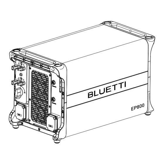
Page 22: Ep800 Inverter
3. EP800 Inverter 3.1 Introduction EP800 inverter is an energy storage photovoltaic off-grid inverter that can handle photovoltaic(PV) input, grid charging, and discharging to loads. It is an important part of the energy storage system. 3.2 Inverter Overview 3.2.1 Appearance... - Page 23 3.2.3 Interface Table 3-3 Left Right Name Name PV1 Input BLEED VALVE PV2 Input COM1 Port (NC) COM2 Port (NC) DC Switch BAT- Terminal DRMs Port (Generator Input) LED Indicator USB Port LINK PORT1 BACKUP Terminal LINK PORT2 GRID Terminal BAT+ Terminal GND Terminal (Grounding) JUST POWER ON...
- Page 24 3.2.4 Interface Description Table 3-4 Type of Cable Terminal Cable specification Description Required BAT+: to the battery Standard BAT+ terminal accessories BAT-: to the Standard battery BAT- terminal accessories PV1+: to the positive terminal of solar panel Conductor Outdoor multi-core PV1-: to the negative cross-sectional copper cable...
- Page 25 The USB drive should be formatted as FAT32 with no more than 32G in size. 3.2.6 DRMs Port The EP800 ESS offers the flexibility to be upgraded for solar energy storage, allowing you to harness more power form the sun. Additionally, it features a DRM interface specifically designed to serve as a convenient ignition reserve port for diesel...
-
Page 26: Led Indicator
When a fault occurs, the buzzer emits a series of 5 beeps. Each beep lasts for 2 seconds, with a 3-second interval between each beep. Note: The buzzer alarm can be turned off in the BLUETTI App. JUST POWER ON... -
Page 27: Inverter Cables
BLUETTI support team. Hardware LLC1 current overcurrent input Hardware LLC2 current overcurrent input Hardware PV1 fault Please contact the BLUETTI support team. Hardware PV2 fault Please contact the BLUETTI support team. Hardware Overcurrent input Please contact the BLUETTI support team. -
Page 28: B500 Battery
The B500 battery energy storage system is designed for residential and light commercial use. Single B500 battery pack has a capacity of 4.96kWh. BLUETTI EP800 ESS supports 4 *B500 units for a whopping 19.84kWh, enough to power a house for several days. - Page 29 4.2.2 Interface Table 4-2 Left Right Name Name BAT- terminal 1 Bleed valve 1 Pack link-in BAT+ terminal 2 Pack link-out Power button BAT- terminal 2 Grounding port 1 Main switch Grounding port 2 BAT+ terminal 1 Bleed valve 2 Inverter signal port (TO Pcs) JUST POWER ON...
- Page 30 4.2.3 Dimensions Table 4-3 (Unit: in/mm) 24.645in(626mm) 12.755in(324mm) Front Right 4.2.4 Interface Description Table 4-4 Interface Description Inverter signal port For communication between inverter and battery packs. Only the top (To Pcs) B500 needs to be connected to the LINK PORT 2 of the inverter. For communication between battery packs.
-
Page 31: Led Indicators
4.3 LED Indicators Table 4-5 Light Description Note B500 is not started. Can operate the circuit breaker. B500 is running. Can not operate the circuit breaker. Flash at 0.5Hz B500 is shutting down. Can not operate the circuit breaker. If all indicators are flashing, the battery module is temporarily unavailable and is restoring, please wait patiently. -
Page 32: Iot Controller
BLUETTI server via the WiFi network. By registering the EP800 ESS with your BLUETTI account, you’re able to monitor and control this unparalleled power plant anytime and anywhere. -
Page 33: Safety Instructions
5.3 Safety Instructions • The IoT controller is ONLY applicable to BLUETTI products only. • Do not keep the controller near heat sources or in high temperatures. • Do not store the controller with flammable liquids, gases, or explosive materials. -
Page 34: Connection And Operations
Step2: Turn on EP800, and the IoT controller starts up automatically. Step3: Configure the controller in BLUETTI app. • Scan the QR code below to download the BLUETTI App, or search for “BLUETTI” in the App Store/Google Play. • The BLUETTI app connects to EP800 ESS via Bluetooth or WiFi. Tap “LOGIN/REGIS- TER”... - Page 35 • Check your email for verification code from BLUETTI server, and fill in the code to activate your BLUETTI account. JUST POWER ON...
-
Page 36: System Installation
6. System Installation Danger • When the EP800 ESS is not activated, the grid side and off-grid side are directly connected. Therefore, it is important not to touch any exposed terminals to ensure safety. • When the grid side is powered on, the off-grid side will also be energized with AC output. -
Page 37: Preparation
6.2 Preparation 6.2.1 Check Packing List Upon receiving the package, we kindly ask you to carefully inspect and verify the presence of all components and accessories included. EP800 Inverter Packing List Table 6-1 Picture Description Qty. EP800 inverter Bracket #1... - Page 38 6 for AC cable protection case, pre-installed on EP800 inverter) M8*12 screw (For battery power cable) M6*12 screw (For bracket, pre-installed on EP800 inverter) M5*10 screw (4 for fixing device to the bracket, 2 for PV grounding) M4*10 screw (For exterior trim) M8*60 expansion bolt Self-tapping screw, ST8×40...
- Page 39 Red battery power cable (Positive) Black battery power cable (Negative) IoT Controller Mounting bracket (IoT controller) Expansion wall plug M3 tapping screw (KA3*25) DRMs communication cable (4m) JUST POWER ON...
- Page 40 B500 Battery Packing List Table 6-2 Picture Description Qty. B500 Battery Module Bracket #1 Bracket #2 M5 hex nut Left cover Right cover M4*8 screw (for fastening covers) M5*10 screw (for brackets) Communication cable Red battery expansion cable (Positive) JUST POWER ON...
- Page 41 Black battery expansion cable (Negative) Grounding cable M8*60 expansion bolt (for brackets) Self-tapping screw, ST8×40 M6*12 screw (Grounding cable) Spare screw kit 6.2.2 Base Packing List Table 6-3 Base Packing List Picture Description Quantity Base JUST POWER ON...
- Page 42 6.2.3 Required Tools Table 6-4 Required Tools Picture Description Electric drill (5/8/10mm) Socket wrench set Torque wrench Flat screwdriver Cross screwdriver (4mm) MC4 spanner Cable cutter Cable stripper Cable Crimper Multimeter (DC voltage ≥ 1000VDC) JUST POWER ON...
- Page 43 Marker Measuring tape Level ruler Box cutter Heat shrink tubing Heat gun Cable tie Anti-static gloves Protective goggle Mask Safety-toe shoes JUST POWER ON...
-
Page 44: Installation Requirements
Vacuum cleaner 6.3 Installation Requirements 6.3.1 Environment Requirements • Install the EP800 ESS in a well-ventilated and spacious area to ensure good heat dissipation. • The EP800 ESS has an IP65 rating and can be installed indoors and outdoors. Please note that if you place the system outside the house, use a cabinet to protect it from direct sunlight, as this may cause a degradation in system performance. - Page 45 Danger 6.3.2 Location Requirements • The EP800 ESS should be installed on a firm, flat, level base. • Do not install the system on flammable materials. • Consider the weight and placement of components to ensure adequate structural support.
-
Page 46: Stacking The Units
3 layers 4 layers 5 layers 24.724 in Ø0.315 in 24.724 in Ø0.315 in 24.724 in Ø0.315 in Fig. 6-3 (Unit: in) 6.4 Stacking the Units Step 1: Place the base on the ground and adjust the height of leveling feet so that the base stands stably on the ground. -
Page 47: Install The Iot Controller
#1 and M8 expansion bolts. Secure the connection with M8 and M5 nuts. Step 5: Repeat Step3 and 4 to secure all battery packs. Step 6: Follow the same steps to install the EP800 inverter on top. EP800 Wall... - Page 48 0.94in (24mm) 2- 5.0 Fig. 6-6-1 Fig. 6-6-2 Bracket Expansion Wall Plug Self-tapping Screw Fig. 6-6-3 Fig. 6-6-4 Controller Fig. 6-6-5 Fig. 6-6-6 Fig. 6-6 JUST POWER ON...
-
Page 49: Electrical Connection
6.6 Electrical Connection 6.6.1 Cables Table 6-5 Cables Picture Cable Red battery power cable (Positive) Black battery power cable (Negative) Communication cable Red battery expansion cable (Positive) Black battery expansion cable (Negative) Grounding cable 6.6.2 Connection Procedure Connect Battery Power Cables Connect Communication Cables Connect Grounding Cables Start... - Page 50 Fig. 6-8 JUST POWER ON...
- Page 51 See “①” “②” of Figure 6-9-1 and 6-9-2. Step 2:Connect the top B500 to EP800 inverter via the battery power cables - black cable for negative terminals, red for positive terminals. See “③” “④” of Figure 6-9-1and 6-9-2.
- Page 52 Figure 6-9-1 Figure 6-9-2 Figure 6-9-2 JUST POWER ON...
- Page 53 Figure 6-9-2 Figure 6-9-2 Max. Torque: 6Nm Max. Torque: 1.2Nm 1. Inverter BAT- terminal (Black) 2. Black battery power cable (BAT-) 3. M8*12 screws 4. Black protection cover (BAT-) Figure 6-9-3 5. M4*12 screws JUST POWER ON...
- Page 54 Link Port 2 of the EP800 inverter. See Fig. 6-10 “②”. Step3: Connect the IoT controller to the EP800 inverter. See Fig. 6-10 “③”. Note: For how to integrate multiple B500s to the EP800 ESS, please refer to Fig. 6-8. JUST POWER ON...
- Page 55 IoT Controller Figure 6-10 6.6.5 Connect Grounding Cables Danger The positive and negative terminals of the PV (photovoltaic) system inverter should not be grounded, as it may lead to inverter failure. However, it is important to ground all non-current carrying metal parts, including brackets, distribution boxes, inverter enclosures, battery pack enclosures, and other relevant components.
- Page 56 The cavity formed after crimping the conductor crimp strip shall wrap the core wires completely. The core wires shall contact the terminal closely. L2=L1+3mm Terminal block L2 is 3mm longer than L1 Wire 6-11-1 L4≥1mm Visible wire Qualified L3≥2mm Wire even or bulge up to 1mm 6-11-2 6-11-3...
- Page 57 DC switch on the inverter has been set to “OFF”. Step 1: It is recommended to use a 12AWG outdoor power cable. Disconnect the cable connector from the EP800 positive and negative connectors. (You’re strongly recommend to distinguish the positive and negative connectors with different colors.)
- Page 58 MC4 Wrench 1. Positive metal terminal 2. Negative metal terminal Figure 6-12-3 Figure 6-12-4 Figure 6-12-5 Figure 6-12-6 Remove the PV connector Figure 6-12-7 JUST POWER ON...
- Page 59 6.6.7 Connect GRID and BACKUP Cables Step 1: Prepare neutral wire, fire wire and grounding wire (White, black, yellow-green 8AWG outdoor power cables and RNB8-6 OT terminals are recommended.). Strip the cables according to Fig. 6-13-1. Step 2: Insert the exposed core wires into the OT terminal and crimp them with a crimper, as shown in Fig.
- Page 60 M6 Screws M6 Screws Max. Torque: 3.0Nm Max. Torque: 3.0Nm Figure 6-13-3 Figure 6-13-4 AC cable protection case Hose connection nut AC cable protection case Figure 6-13-5 Figure 6-13-6 Waterproof conductor Hose connection nut BACKUP cables GRID cables M4 *12 screws, Max. Torque: 1.2Nm Figure 6-13-7 Fig.
-
Page 61: System Check
Waterproof hose fitting Figure 6-11-8 Waterproof hose 7. System Check 7.1 Preliminary Check Check the followings before first use. • Confirm that all components of the system are installed according to specific requirements. • Make sure the PV+ / PV- and BAT+ / BAT- cables are connected with correct polarity and proper voltage. - Page 62 Step 3: Wait for about 40 seconds till the inverter indicator keeps steady green. Step 4: Switch on the AC circuit breakers connected to the inverter GRID terminal. Step 5: Power on the system via BLUETTI app. For details, please refer to BLUETTI App Instructions.
-
Page 63: System Maintenance
USB drive, or EP800 will report a USB Format Error. Step 7: Pair EP800 ESS with BLUETTI app, then you can check the firmware version in System information>> Firmware version. If any of the following occurs, please try the solutions provided. -
Page 64: System Disposal
9. System Disposal 9.1 Remove the inverter When the inverter is no longer in use, it must be disposed of properly. Step 1: Power off the system. Step 2: Disconnect all electrical connections to the inverter, such as signal cable, DC input cable, power cable, AC input cable, grounding cable, etc. -
Page 65: Specifications
10. Specifications AC Port AC (Grid-tied) Item Description Note Wiring L1/L2/N/G Rated Voltage 120VAC / 240VAC Voltage Range 110V-126V / 220V-252V Input Frequency Range 55Hz-65Hz Bypass + Grid Charging Maximum Input Apparent Power 12000VA Bypass + Grid Charging Maximum Input Current Maximum Input Power 7680W Grid Charging... - Page 66 DC Port PV Input Item Description Note Maximum Input Power 9000W MPPT Channel 3000W+ 6000W Array In Series Maximum Input Voltage 550V MPPT Voltage Range/Rated 150V~500V/360V Single MPPT Maximum Input Current 12.5A/25A Single MPPT Maximum Short-circuit Current 15A/30A MPPT Efficiency 99.9% PV Inversion Efficiency 96.0% Peak...
- Page 67 General AC (Grid-tied) Item Description Note Relative Humidity 5%-95% Static Power Standby Power Operating Temperature -4°F~104°F/-20℃~40℃ Noise ≤50dB (A) Cooling Forced air cooling Protection Grade IP65/NEMA 4X Working Altitude ≤6561ft/2000m 24.645inx12.755inx14.488in Dimensions (L*W*H) /626mm × 324mm × 368mm Net Weight 97lbs/44kg Communication USB / WiFi / Bluetooth...
-
Page 68: Troubleshooting
Hardware Battery Overvoltage Turn off the inverter and wait 30 minutes to restart it. If the symptom persists, Hardware Inverter Overcurrent please contact the BLUETTI support team. Hardware Inverter2 Overcurrent Hardware LLC1 Input Overcurrent Hardware LLC2 Input Overcurrent Auxiliary Power Undervoltage... - Page 69 Check if the inverter fan operates well. Turn off the inverter and wait 30 minutes Zero Drift Anomaly to restart it. If the symptom persists, please contact the BLUETTI support team. Hardware Input Overcurrent Check if the DC voltage is too low. DC Input Voltage Low...
- Page 70 Operating Ambient Temperature Anomaly Temperature 1 Anomaly Please make sure use the system within specific temperature range. If the symptom persists, Temperature 2 Anomaly please contact the BLUETTI support team. Temperature 3 Anomaly Temperature 4 Anomaly BMS Charge Protection BMS Discharge Protection Check the details on BLUETTI app.
- Page 71 105. 106. Generator Voltage Anomaly 107.-128. Please reconfigure the settings on EEPROM Read and 129. BLUETTI app. If the symptom persists, Write Anomaly please contact the BLUETTI support team. 130. Grid Overvoltage - ARM 131. Grid Undervoltage - ARM 132.
-
Page 72: Faqs (Frequently Asked Questions)
A: The startup time may vary slightly depending on the startup method, but it should not exceed 3 minutes. Can I connect a solar system that exceeds the PV input limits of EP800 ESS? Will the EP800 ESS automatically adjust the input current? It depends on the voltage of your solar system. - Page 73 (3) With the same connector (MC4). Why isn't my solar system able to charge the EP800 ESS? (1)Make sure that the PV switch of the EP800 ESS is in the "ON" position. (2)Check the connections of the solar panel and the PV input cables.
-
Page 74: Fcc Warning
13. FCC Warning This equipment has been tested and found to comply with the limits for a Class B digital device, pursuant to part 15 of the FCC Rules. These limits are designed to provide reasonable protection against harmful interference in a residential installa- tion. - Page 75 This device contains licence-exempt transmitter(s)/receiver(s) that comply with Innovation, Science and Economic Development Canada’s licence-exempt RSS(s). Operation is subject to the following two conditions: (1) This device may not cause interference. (2) This device must accept any interference, including interference that may cause undesired operation of the device.
- Page 76 For more information, please visit: Customer Service Tel: 800-200-2980 (Monday to Sunday 9:00-17:00) Mail: sale@bluettipower.com (Pre-sales), service@bluettipower.com (After-sales) Web: https//www.bluettipower.com Add: 6185 S Valley View Blvd Ste D.Las Vegas,NV 89118. @ BLUETTI Support @ BLUETTI Official @ bluetti_inc @bluetti.inc @bluetti_official service@bluettipower.com...
Need help?
Do you have a question about the EP800 and is the answer not in the manual?
Questions and answers