Table of Contents
Advertisement
Quick Links
Advertisement
Table of Contents

Related Manuals for uAvionix AV-20


Summary of Contents for uAvionix AV-20
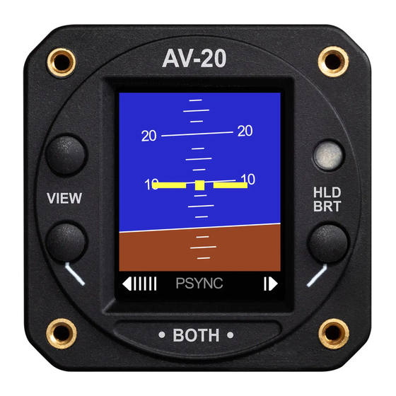
- Page 1 AV-20-E Installation Manual UAV-1004048-001 Rev A...
-
Page 2: Legal Notices
Warnings / Disclaimers uAvionix is not liable for damages arising from the use or misuse of this product. This equipment is classified by the United States Department of Commerce’s Bureau of Industry and Security (BIS) as Export Control Classification Number (ECCN) 7A994. -
Page 3: Table Of Contents
Document Revisions Revision Date Description of Change 06/28/2024 Initial Release Table of Contents Legal Notices ........................2 Warnings / Disclaimers ....................2 1 System Description ...................... 5 Model Variants & ......................6 2 Required Interfaces ..................... 6 2.1 Equipment Connections ..................7 2.2 Outside Air Temp Input.................. - Page 4 UAV-1004048-001 Rev A...
-
Page 5: System Description
1 System Description The uAvionix AV-20-E Multi-Function Displays provide a wide array of supplemental flight information. Features Include: • BeaconX Transponder Control • AoA Display (Voice Alerting & Peaks) • G-Meter Display (Voice Alerting & Peaks) • Attitude (Roll / Pitch) •... -
Page 6: Model Variants
AV-20-E (Part Number UAV-1003626-001): The (E)xperimental model includes BeaconX transponder control and an altitude ceiling of 35,000’ • AV-20-S (Part Number UAV-1003310-001 or U-1002-0): The NORSEE certified (S)ensor model does not include BeaconX transponder control and has an altitude ceiling of 25,000’. -
Page 7: Equipment Connections
The model and part number are shown on the splash screen on power-up, and on the SETUP -> SYSTEM INFO page. 2.1 Equipment Connections All connections are provided on the single 9-Pin D-sub connector and the two pneumatic fittings. The unit connects to aircraft power via a normal power circuit with a dedicated 1 Amp breaker. -
Page 8: Operating Limits
connect fittings are utilized. Reference the wiring diagram for details on how to release the tubing from the fitting. 3 Operating Limits The following operational limitations are applicable: Operating Limits Angle of Attack Range -10° to +30° Angle of Attack Resolution 1°... -
Page 9: System Specifications
3 Watts (0.25Amps @ 12VDC) Input Power Max 6 Watts (0.50 Amps @ 12VDC) Required Circuit Breaker 1 Amp Operation on Battery (AV-20-S) Up to 30 Minutes depending on conditions 1.5V RMS, load 16 Ohm – 10 kOhm Audio output Physical Attributes 2 ¼”... -
Page 10: Intended Function
5 Intended Function Reference the AV-20-E Pilot’s Guide UAV-1004049-001 Section 2 for intended functionality. UAV-1004048-001 Rev A... -
Page 11: Installation
• Apply power and perform setup Proper mounting orientation is important to ensure performance of the AV-20. Confirm the unit is oriented level in the roll-axis when installed in the panel. To do so, ensure the aircraft is level and loosen the mounting screws. Visually align the slid / skid indicator in the middle by rotating the unit, then tighten the screws. -
Page 12: Wiring Diagram
QUICK CONNECT: Accessories: MIL-C-27500, 22 or 24 gauge. MINIMIZE RISK OF DAMAGING THE QUICK-CONNECT FITTING ** PUSH RELEASE RING IN TOWARD UNIT TO RELEASE AV-20 AIRCRAFT STATIC SYSTEM ¼ “ OD NYLON / POLYETHYLENE TUBE (OR EQ) RELEASE AIRCRAFT PITOT... -
Page 13: Setup
Table 5 - tailBeaconX Wire Chart 6.4 Setup Refer to AV-20-E Pilot’s Guide UAV-1004049-001 for detailed setup options and procedures. All options are available to the pilot to configure as desired. Some options are disabled when airspeed > 40 kts is detected and some calibration options are disabled if vibration is detected indicating a running engine. -
Page 14: Beaconx Control Head
6.5 BeaconX Control Head 6.5.1 Wiring 6.5.2 Operation Select SET then ENT ENT ENT ENT MODE Change UP / DWN Select SET then ENT Squawk Change UP / DWN Ident Activate UP Short Press Reset Squawk Set to VFR UP Long Press UAV-1004048-001 Rev A... -
Page 15: Calibration & Limits
7 Calibration & Limits All calibration and limit settings are available to the pilot but some are prohibited under flight conditions. These consist of: Setting Exclusion Condition Upper and Lower AoA alerting Thresholds None Upper and Lower G-Alerting Thresholds None OAT Temperature Trim None Hard Calibration... -
Page 16: Instructions For Continued Maintenance And Operation
The AV-20-E system may be used for supplemental information but may not replace any equipment required under 14 CFR 91.205. • The AV-20-E system is not a required system and may not be used as a substitution for the certificated aircraft system. •... -
Page 17: Pitot-Zero
AV-20-E to simulate multiple airspeeds. To execute this function, select the SETUP page on the AV-20-E. Scroll down to the IAS TRIM submenu and press SEL. Now select LOW TRIM and press SEL. Note that the AV- 20-E detects large vibrations to prevent this operation occurring during flight. -
Page 18: Altitude Trim
AV-20-E is equal to the airspeed indicated on the test set. Press OK to save the value. Note that if the HIGH TRIM has never been set, the trim value will be “---” which means it is operating in 1 point trim mode. If HIGH TRIM and LOW TRIM values are equal, it will behave the same as 1 point trim mode. -
Page 19: Beaconx Ground Test Mode
When test is complete, cycle tailBeaconX power to exit test mode. 8.9 Software Update Please refer to the service bulletin that accompanies any new software for the AV-20-E. RS-232 serial is used for updating software. The wiring diagram is as shown below. If a tailBeaconX is installed with the AV-20-E, a ‘go between’... - Page 20 Detailed steps are as follows: 1. Remove the two battery cover hold-down screws (T8). UAV-1004048-001 Rev A...
- Page 21 2. Remove the battery pack and tape from the battery cover and pull gently on the battery wires close to the connector to disconnect the battery from the unit. Keyed Battery Connection Pull to Disconnect UAV-1004048-001 Rev A...
- Page 22 3. On the new battery assembly, peel the protective paper from the double-sided tape. Affix the new battery pack to the battery cover, leaving the connection wires from the battery toward the right side of the cover (orientated overhang at the top). Overhang Wires to the right side of...
-
Page 23: Troubleshooting
Return to factory for service if unit does not align within 3 aligning annunciator remains minutes of power-on. Battery Contact uAvionix support.to procure a replacement Battery indicator shows FAIL. battery. Replacement instructions are in section 8.10 of this manual Trim...
Need help?
Do you have a question about the AV-20 and is the answer not in the manual?
Questions and answers