Table of Contents
Advertisement
Quick Links
Advertisement
Table of Contents

Related Manuals for uAvionix SkyLink


Summary of Contents for uAvionix SkyLink
- Page 1 SkyLink User and Installation Manual REVISION B UAV-1006203-001 Page 1 | 25...
-
Page 2: Proprietary Rights
For the duration of the warranty period, uAvionix, at its sole option, will repair or replace any product which fails under normal use. Such repairs or replacement will be made at no charge to the customer for parts or labor, provided that the customer shall be responsible for any transportation cost. -
Page 3: Revision History
3 Revision History Revision Date Comments January 2022 Initial Release April 29 2022 Updates to installation procedures and updated diagrams UAV-1006203-001 Page 3 | 25... -
Page 4: Regulatory Statements
4.2 SkyLink Use Prior to FCC Authorization Those wishing to use SkyLink airborne and ground radios before they receive FCC authorization must request one or more Experimental FCC Transmit Licenses. First, though, one or more FAA Coordination Numbers must be requested and obtained, signifying the FAA's approval to use its protected C-band frequencies. -
Page 5: Table Of Contents
Proprietary Rights .................. 2 Warranty ....................2 Revision History ..................3 Regulatory Statements ................4 FCC Statement ................4 SkyLink Use Prior to FCC Authorization ......... 4 Contents ....................5 Introduction .................... 7 System ....................7 Installation ....................9 Ground Radio System (GRS) ............9 8.1.1... - Page 6 11.1 Hub Firmware Update ..............23 11.2 GRS Radio Firmware Update ............24 11.3 ARS Radio Firmware Update ............25 12 Support ....................25 UAV-1006203-001 Page 6 | 25...
-
Page 7: Introduction
SMA Coaxial antenna leads SkyLinkApp and Documentation SkyLink GRS and ARS Radios Each SkyLink radio system is a purpose-built diversity system with two receive channels and one transmit channel. The system includes built-in link management that handles remote configuration and performance statistics. - Page 8 The truFYX provides GPS signal to the airborne system. Internal and external mount configurations are available. Figure 1 shows a typical system with a SkyLink Ground Radio System (GRS) and a SkyLink Airborne Radio System (ARS) managed by uAvionix SkyLine infrastructure.
-
Page 9: Installation
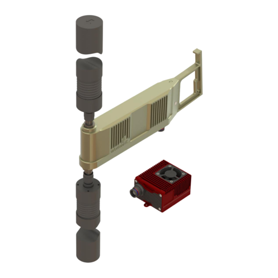
The SkyLink Mounting Bracket is angled 6 degrees upward to maximize airborne coverage. 1. Secure the SkyLink Mounting Bracket to a pole with the included stainless steel hose clamps. 2. Align the GRS with the Mounting Bracket and slide the GRS into place over the end of the bracket. - Page 10 5. A directional arrow on the end cap of each antenna denotes the transmit and receive direction of the antenna. The antennas have 110 degrees of horizonal sector coverage (55 degrees on either side of the directional arrow). Point both antenna arrows in the direction of your ARS for best performance.
-
Page 11: Mounting Skylink Hub
8.1.2 Mounting SkyLink Hub Figure 4 Mounting SkyLink Hub The SkyLink Hub Mounting Bracket is not angled. The Hub mounts perpendicular to the pole, and the GPS antenna should point up. 1. Fasten the Hub Mounting Bracket to a pole with the included stainless steel hose clamps. -
Page 12: Connections
8.1.3 Connections Connect SkyLink GRS to the SkyLink Hub and connect the Hub to a POE++ switch with network access. Ensure that the two directional antennas or RF loads are attached to both RF ports on the GRS before powering on. - Page 13 Mode A (endspan), Mode B (midspan) Power Management Power Class 6 Maximum Cable Length 100 meters Figure 6 - SkyLink M12 Connector Pinout Caution! Absolute maximum DC voltage +57 V. Higher DC voltage will permanently damage the equipment. UAV-1006203-001 Page...
-
Page 14: Airborne Radio System (Ars)
8.2 Airborne Radio System (ARS) 8.2.1 Mounting SkyLink ARS Install the SkyLink ARS in the airframe in a location that allows easy access to the autopilot and minimal RF coax length for antenna installation. Install the omni antennas on the airframe in a location that reduces shadowing and interference between the omni antenna and the GRS. - Page 15 The Figure below shows each component and its corresponding pinout. Figure 7 ARS Wiring Harness UAV-1006203-001 Page 15 | 25...
-
Page 16: Configuration
9.1 Ground Radio System (GRS) 9.1.1 SkyLink Hub Network Settings SkyLink Hub settings are accessed via web browser from a PC or mobile device on the same Local Area Network (LAN) as the powered SkyLink Hub. The IP address assigned by the DHCP server is the base URL. - Page 17 DHCP server. These settings are ignored in a typical system. Figure 9 SkyLink Hub Network Settings In a network without DHCP, set the IP Address field to assign a static IP to the SkyLink Hub. Fill in the appropriate values for Subnet, Gateway, and DNS in the network and press Save.
-
Page 18: Grs Settings
Open the uAvionix SkyLinkApp application using a Windows computer with network access to your SkyLink GRS. Input the IP Address of your SkyLink Hub and the Control Port from the SkyLink Hub Settings page in the COM Settings box. Optionally, next to Device Name, type in a friendly name for the radio and press Save. - Page 19 Figure 11 SkyLink App Radio Configuration SkyLink GRS = Ground Station Type SkyLink ARS = Air SkyLink GRS with SkyLine = Infrastructure Frequency Get / Set Radio C-Band Frequency in Hz Versions Get version details from connected SkyLink radios UAV-1006203-001 Page 19 | 25...
-
Page 20: Airborne Radio System (Ars)
(i.e. COM1). Optionally, next to Device Name, type in a friendly name for the radio and press Save. This allows for quick switching between different radio connections. Figure 12 SkyLink App ARS Connection ARS Configuration See Section 9.1.2 – GRS Configuration. -
Page 21: Operation
GPS position lock, and a PPS timing signal. To verify link, connect the GRS to the SkyLinkApp and go to the Status Tab. When the data arrives, skyLinkApp will begin graphing the radio link statistics. Figure 13 SkyLink App Radio Status UAV-1006203-001 Page... -
Page 22: Mission Planner Example
10.2 Mission Planner Example 1. Connect the skyLink ARS to an Autopilot via the User data link connection. 2. Verify the ARS and GRS have a link 3. Open ArduPilot Mission Planner application. 4. In the communication drop down menu (upper right corner), select TCP. -
Page 23: Firmware Update
Note: The update is canceled if the Hub is powered off or the webpage is closed. Wait for the Hub to reboot before proceeding. When the file transfer is complete, click the Main Page link to return to the SkyLink Hub Settings page. The version number on the Configuration Webpage should reflect the firmware version uploaded. -
Page 24: Grs Radio Firmware Update
11.2 GRS Radio Firmware Update The GRS Radio firmware can be updated via the SkyLinkApp. Connect the GRS to the SkyLinkApp following the steps in section 9.1.2. Press Radio FW Update in SkyLinkApp. A new window will open. Press Select File and select the correct firmware file. Press Connect. -
Page 25: Ars Radio Firmware Update
11.3 ARS Radio Firmware Update The ARS Radio firmware is updated using the SkyLinkApp. Connect the ARS to the SkyLink following the steps in section 9.2.1 then repeat the steps in section 11.2 12 Support For support visit https://uavionix.com/support/ UAV-1006203-001...
Need help?
Do you have a question about the SkyLink and is the answer not in the manual?
Questions and answers