Sign In
Upload
Manuals
Brands
Kontron Manuals
Single board computers
COMe-bCL6
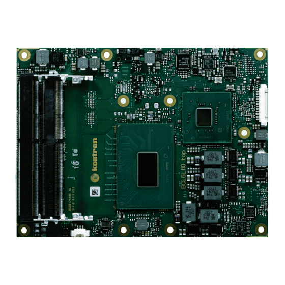
Kontron COMe-bCL6 Single Board Computer Manuals
Manuals and User Guides for Kontron COMe-bCL6 Single Board Computer. We have
1
Kontron COMe-bCL6 Single Board Computer manual available for free PDF download: User Manual
Kontron COMe-bCL6 User Manual (101 pages)
Brand:
Kontron
| Category:
Single board computers
| Size: 6 MB
Table of Contents
Symbols
7
Table of Contents
10
List of Tables
12
List of Figures
13
1/ Introduction
15
Product Description
15
Product Naming Clarification
15
COM Express® Documentation
15
COM Express® Functionality
16
COM Express® Benefits
16
Table 1: Pin Assignment of Type 6 and Come-Bcl6
16
2/ Product Specification
17
Module Variants
17
Commercial Grade Modules (0°C to +60°C)
17
Table 2: Commercial Grade Modules (0°C to +60°C)
17
Extended Temperature Grade Modules (E1, -25 °C to +75 °C)
18
R E2S Modules (R E2S, -40°C to +85°C)
18
Table 3: R E2S Modules (R E2S, -40°C to +85°C)
18
Accessories
19
Table 4: Product Specific Accessories
19
Table 5: Come Type 6 Specific Accessories
20
Table 6: General Accessories
20
Table 7: Memory Modules
21
Functional Specification
22
Block Diagram Come-Bcl6
22
Figure 1: Block Diagram Come-Bcl6
22
Front and Bottom View
23
2.3.2.1. Front View
23
Figure 2: Front View Come-Bcl6
23
2.3.2.2. Bottom View
24
Figure 3: Bottom View Come-Bcl6
24
Technical Data
25
Table 8: Technical Data
25
Processor
26
Table 9: Specifications of the Come-Bcl6 Processor Variants
27
Chipset
28
Platform Controller Hub (PCH)
28
System Memory
28
Hardware Monitor (HWM)
28
Table 10: PCH QM370 and CM246 Features
28
Table 11: System Memory
28
Trusted Platform Module (TPM)
29
SPI BIOS Memory
29
Onboard FAN Connector
29
Rapid Shutdown
29
General Purpose PCI Express 3.0
29
Table 12: Onboard FAN Connector
29
Table 13: General Purpose PCI Express 3.0
29
PCI Express Graphics 3.0 (PEG)
30
Universal Serial Bus (USB)
30
Table 14: PCI Express Graphics 3.0
30
Table 15: Universal Serial Bus (USB)
30
Serial ATA 3.0
31
Gigabit Ethernet
31
Table 16: USB Overcurrent
31
Table 17: Serial ATA 3.0
31
Table 18: Supported Ethernet Features
31
Graphic Interfaces
32
2.3.17.1. Display Resolution
32
Video Graphics Array (VGA)
32
High Definition (HD) Audio
32
Table 19: Digital Display Interfaces Overview
32
Table 20: HDA Features
32
Inter-Integrated Circuit (I2C)-Bus
33
Power Supply Control Settings
33
General Purpose Ios (Gpios)
33
Fan Control
33
Table 21: Implemented Power Supply Control Settings
33
Table 22: Fan Signals
33
UART Serial Ports
34
Bios/Software Features
34
Come Features
34
Kontron Features
34
Table 23: UART Signals
34
Table 24: BIOS and Software Features
34
Table 25: Come Specification Features
34
Table 26: Kontron Features
34
Electrical Specification
35
Power Supply Voltage
35
Power Supply Rise Time
35
Power Supply Voltage Ripple
35
Power Consumption
35
Table 27: Power Supply Specifications
35
Table 28: Single Supply Current Consumption @ 12 V with AVX2 Load
35
Table 29: Power Supply and Management
36
Power Supply Control Settings
37
Table 30: Power Management Options
37
Table 31: Power Supply Control Settings
37
Power Supply Modes
38
2.4.7.1. ATX Mode
38
2.4.7.2. Single Supply Mode
38
Table 32: ATX Mode Settings
38
Table 33: Single Supply Mode Settings
38
Thermal Management
39
Heatspreader and Cooling Solutions
39
Operating with Kontron Heatspreader Plate (HSP) Assembly
39
Operating Without Kontron Heatspreader Plate Assembly
39
On-Board Fan Connector
39
Table 34: Heatspreader Test Temperature Specifications
39
Table 35: 3-Pin Fan Connector Pin Assignment
39
Table 36: Electrical Characteristics of the Fan Connector
40
Environmental Specification
41
Temperature
41
Humidity
41
Table 37: Temperature Grade Specifications
41
Table 38: Humidity Specifications
41
Standards and Certifications
42
Table 39: Standards and Certifications
42
Mtbf
43
Figure 4: MTBF Temperature De-Rating
43
Mechanical Specification
44
Dimensions
44
Height
44
Figure 5: Module Dimensions
44
Figure 6: Module Height
44
3/ Features and Interfaces
45
Lpc
45
Serial Peripheral Interface (SPI)
45
SPI Boot
45
Table 40: Supported BIOS Features
45
Table 41: SPI Boot Pin Configuration
45
Using an External SPI Flash
46
Table 42: Supported SPI Boot Flash Types for 8-SOIC Package
46
External SPI Flash on Modules with Intel® ME - in the PRD
47
External BIOS ROM Support/Spi
47
3.4. Fast I2C
47
3.5. Uart
47
Table 43: Reserved SM-Bus Addresses for Smart Battery Solutions on the Carrier
47
Triple Staged Watchdog Timer (WDT)
48
Basics
48
WDT Signal
48
Table 44: Triple Stage Watchdog Timer- Time-Out Events
48
Real Time Clock (RTC)
49
Kontron Security Solution APPROTECT
49
Rapid Shutdown
49
Crowbar Implementation Details
49
Shutdown Input Circuit Details
50
4/ System Resources
51
Memory Area
51
Table 45: Designated Memory Locations
51
I/O Address Map
52
Table 46: Designated I/O Port Addresses
52
Legacy Interrupt (IRQ) Lines
54
Peripheral Component Interconnect (PCI) Devices
54
I2C Bus
54
Table 47: List of Interrupt Requests
54
Table 48: I2C Bus Port Addresses
54
System Management (SM) Bus
55
Table 49: Designated I/O Port Addresses
55
5/ Interface Connectors X1A and X1B
56
X1A and X1B Signals
56
Table 50: General Signal Description
56
Figure 7: X1A and X1B Come Interface Connectors
56
X1A and X1B Pin Assignment
57
Connector X1A Row A1 - A110
57
Table 51: Connector X1A Row a Pin Assignment (A1- A110)
57
Connector X1A Row B 1 - B 110
62
Table 52: Connector X1A Row B Pin Assignment (B1-B110)
62
Connector X1B Row C 1 - C 110
66
Table 53: Connector X1B Row C Pin Assignment (C1-C110)
66
Connector X1B Row D 1 - D 110
70
Table 54: Connector X1B Row D Pin Assignment (D1-D110)
70
6/ Maintenance
74
Blue Screen after BIOS Update
74
7/ Uefi BIOS
75
Starting the Uefi BIOS
75
Table 55: Navigation Hot Keys Available in the Legend Bar
75
Setup Menus
76
Main Setup Menu
77
Table 56: Main Setup Menu Sub-Screens and Functions
77
Figure 8: Main Setup Menu
77
Advanced Setup Menu
79
Table 57: Advanced Setup Menu Sub-Screens and Functions
79
Figure 9: Avanced Setup Menu
79
Chipset Setup Menu
85
Figure 10: Chipset Setup Menu
85
7.2.3.1. Chipset: System Agent Configuration
86
Table 58: Chipset: System Agent Configuration Sub-Screens and Functions
86
7.2.3.2. Chipset > PCH-IO Configuration
87
Table 59: Chipset Set > PCH-IO Configuration Sub-Screens and Functions
87
Security Setup Menu
90
Table 60: Security Setup Menu Functions
90
Figure 11: Security Setup Menu
90
7.2.4.1. Remember the Password
91
Boot Setup Menu
92
Table 61: Boot Setup Menu Functions
92
Figure 12: Boot Setup Menu
92
Save and Exit Setup Menu
93
Table 62: Save and Exit Setup Menu Functions
93
Figure 13: Save and Exit Setup Menu
93
The Uefi Shell
94
Basic Operation of the Uefi Shell
94
7.3.1.1. Entering the Uefi Shell
94
7.3.1.2. Exiting the Uefi Shell
94
Uefi Shell Scripting
95
Startup Scripting
95
Create a Startup Script
95
Examples of Startup Scripts
95
7.4.3.1. Execute Shell Script on Other Harddrive
95
Firmware Update
96
7.5.1.1. Updating Procedure
96
8/ Technical Support
97
Warranty
97
Returning Defective Merchandise
97
Appendix A: List of Acronyms
99
About Kontron - Member of the S&T Group
101
Advertisement
Advertisement
Related Products
Kontron COMe Ref. Carrier-i T10 TNIV
Kontron COMe Ref. Carrier-i T10 TNIE
Kontron COMe-cBW6
Kontron COMe-cAP6
Kontron COMe-cRP6 E2
Kontron COMe-mAS10 E2 Series
Kontron COMe-mAS10 E2x7211RE 4G/32G
Kontron COMe-mAS10 E2x7835RE 8G/32G
Kontron CompactPCI CP6000
Kontron COMe-bP5020
Kontron Categories
Computer Hardware
Motherboard
Server
Industrial PC
Desktop
More Kontron Manuals
Login
Sign In
OR
Sign in with Facebook
Sign in with Google
Upload manual
Upload from disk
Upload from URL