Table of Contents
Advertisement
Quick Links
Vacuum Gauge
Instruction Manual
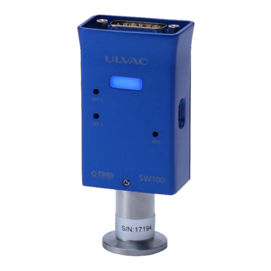
G-TRAN series
Pirani Vacuum Gauge Sensor Unit
Analog Output Type
Serial Communication Type SW100-R
This instruction manual describes the serial numbers after
Please be sure to read this before using this product.
Also, please keep it in a safe place so that you can use it
at any time.
the following numbers.
SW100-A:S/N 00001~
SW100-R:S/N 00001~
ULVAC, Inc. Components Division
I
SK00-9663-EI-003-00
SW100-A
https://www.ulvac.co.jp/en/
Advertisement
Table of Contents

Related Manuals for Ulvac G-TRAN SW100-A


Summary of Contents for Ulvac G-TRAN SW100-A
- Page 1 This instruction manual describes the serial numbers after the following numbers. SW100-A:S/N 00001~ SW100-R:S/N 00001~ Please be sure to read this before using this product. Also, please keep it in a safe place so that you can use it at any time. ULVAC, Inc. Components Division https://www.ulvac.co.jp/en/...
- Page 2 Please fully understand. The copyright of the instruction manual belongs to ULVAC, Inc. It is prohibited to copy any part of the instruction manual without our consent. In addition, it is prohibited to disclose or transfer the instruction manual to a third party without the written consent of our company.
-
Page 3: Safety Precautions
SK00-9663-EI-003-00 Safety precautions Please be sure to read the instruction manual and the following safety precautions in order to use the G-TRAN series sensor unit (hereinafter referred to as "this unit") safely. Repair *WARNING* For repairs, etc., contact the place of purchase, our company, or the network destination described in the instruction manual. - Page 4 SK00-9663-EI-003-00 Power on After connecting the sensor, display, PLC (programmable logic *WARNING* controller), cable, etc. to this unit, turn on the power. Doing so may damage this unit or the equipment connected to this unit or cause a fire. In addition, the filament of the sensor may be disconnected. Excessive pressure in the vacuum chamber Do not connect to a place where the pressure inside the sensor exceeds atmospheric pressure.
- Page 5 SK00-9663-EI-003-00 Usage environment When exposed to accumulated gas such as rotary pump oil mist and CVD (Chemical Vapor Deposition) raw material gas, problems such as *CAUTION* disconnection of filaments and changes in pressure characteristics occur. When using in such an environment, install an isolation valve between this unit and the vacuum chamber, and seal the isolation valve so that it is not exposed to these gases as much as possible.
- Page 6 SK00-9663-EI-003-00 Check for pressure indication Immediately after starting use, check the pressure indication, especially the pressure on the atmospheric pressure side and the zero point side. If necessary, adjust the atmospheric pressure and zero *CAUTION* point. Due to the principle of pirani vacuum gauge, the pressure indication is affected by the environmental temperature.
- Page 7 SK00-9663-EI-003-00 Revision history Date Number Reason 2022/10/3 First edition...
-
Page 8: Table Of Contents
SK00-9663-EI-003-00 Contents BEFORE USING THIS PRODUCTS ........II SAFETY SYMBOL MARKS ..........II SAFETY PRECAUTIONS ..........III REVSION HISTORY ...........VII CONTENTS ............VIII Setpoint operation signal ...24 SPECIFICATION ...... 10 5.3. INPUT SIGNAL NALOG OUTPUT TYPE 1.1..10 NPACKING AND QUANTITY CHECK SW100-A ) ......25 ONLY... - Page 9 SK00-9663-EI-003-00 Writing setpoint1 setting Download/install ..45 value ......31 How to use ....45 Writing setpoint2 setting 11.3. UL-MOBI ..50 NDROID VERSION value ......31 Usage environment ..50 7.5......32 Download/install ..50 HECKSUM 7.6......33 How to use ....50 TATUS SH (Higher status) ..
-
Page 10: Specification
SK00-9663-EI-003-00 Specification Pirani vacuum gauge sensor unit SW100 is a vacuum gauge that can measure low vacuum pressure by connecting a dedicated sensor (SWP series). The SW100 is the next model to the conventional model SW1, and the SW100-A is compatible with SW1-1 and the SW100-R is compatible with SW1-2. -
Page 11: Separately
SK00-9663-EI-003-00 Items that need to be ordered separately D-sub15pin connector (female), Connector for M2.6mm screw ① SW100 ※Unwired Calibration General calibration test report ② ① certificate JCSS calibration certificate Inspection report Traceability certificate Model ISG1 Display unit (using DC24V power supply) Between SW100 and display unit ②... - Page 12 SK00-9663-EI-003-00 Sensor error signal, setpoint1/2 Control output signal Open collector output, negative logic Rating: 30V 50mA 70mW MAX, MAX, D-sub15pin USB Type-C Communication ※USB Type-C can only be used for communication using UL- MOBI. Serial RS-232C/RS-485 communication Communication 9600/19200/38400bps speed Memory function Back pu with EEPROM POWER/ERROR: Power, error LED...
- Page 13 SK00-9663-EI-003-00 SWP- SWP- Model Sensor SWP-16 SWP-25 SWP-P18 SWP-P15 SWP-1S R1/8 CF16 ※Refer to Innner 7.3cm 7.8cm 7.6cm 13.9cm 10.0cm 11.3cm 8.2cm section volume 18.2 Weight ※1 accuracy :The accuracy after atmospheric pressure and zero point adjustment. Please carry out atmospheric pressure and zero point adjustment before use especially.
-
Page 14: Handling Precautions
SK00-9663-EI-003-00 Handling precautions *CAUTION* Please check this chapter before you start using this unit. 2.1. Precautions on operating environment Usage environment Use this unit within the environment specified in the specifications. Usage environment Do not use it in a place where this unit is exposed to water or where the humidity is high and condensation occurs. -
Page 15: Precautions On Power Supply
SK00-9663-EI-003-00 Influence of electrons, ions, etc. If there is a strong source of electrons or ions nearby, not only will the correct pressure not be measured, but it may also cause damage or malfunction of this unit. Please be careful about the mounting position so that it will not be affected by electrons or ions. - Page 16 SK00-9663-EI-003-00 Temperature fluctuation According to the measurement principle of pirani vacuum gauge, the ambient temperature of the sensor affects the measured value. If the ambient temperature deviates significantly from the temperature at the time of calibration (about 25℃), adjust the atmospheric pressure and zero point.
-
Page 17: Precaution On Usage
SK00-9663-EI-003-00 2.4. Precaution on usage Impact If this unit is dropped or installed in a place with large vibrations, the impact or vibration may cause disconnection of the filament of the sensor or damage to this unit. Measurement Please go after aging for 20minutes or more. Shipping packing When transporting this unit, return it to the factory default state. -
Page 18: Name Of Each Part And Explanation Of
SK00-9663-EI-003-00 Name of each part and explanation of function 3.1. SW100 controller section ① ② ⑤ ③ ④ Diagram of SW100 controller section Name Function ① I/O connector I/O connector(D-sub15pin connector(pin)、M2.6mm screw) ② Mating screw Mating screw (M2.6mm screw) for I/O connector fixing. ③... -
Page 19: Sw100 Front Panel Secion
SK00-9663-EI-003-00 3.2. SW100 front panel secion ① ③ ② ④ Diagram of SW100 front panel section Name Function Lights blue when this unit is operating normally. Lights red when the filament of the sensor is disconnection. ① POWER/ERROR LED Flashes blue when zero point adjustment or atmospheric pressure adjustment is performed. -
Page 20: I/Oconnector Analog Output Type Sw100- A
SK00-9663-EI-003-00 3.3. I/O connector Analog output type SW100-A Analog output type SW100-A I/O connector Pin layout(D-sub15pin connector(male) M2.6mm screw) Terminal This unit Function number Power supply Power supply for driving this unit DC 14V to 30V Outputs signal when the filament is Sensor error Lo output dsconnected, etc. -
Page 21: I/Oconnector Serial Communication Type Sw100-R
SK00-9663-EI-003-00 3.4. I/O connector Serial communication type SW100-R Serial communication type SW100-R I/O connector Pin layout(D-sub15pin connector(male) M2.6mm screw) Terminal This unit Function number Power supply Power supply for driving this unit DC 14V to 30V Outputs signal when the filament is Sensor error Lo output dsconnected, etc. -
Page 22: Power Supply Internal Circuit
SK00-9663-EI-003-00 Power supply internal circuit This chapter describes the power input section of this unit. ・ Signal GND [15pin] is a ground for signals such as pressure signal output, set point, and serial communication. ・ The power supply GND [9pin] and the signal GND [15pin] are common after passing through the filter internally. -
Page 23: Signals
SK00-9663-EI-003-00 Signals This section describes the signals output from this unit and the signals input to this unit. 5.1. Pressure signal output This unit outputs the measured pressure as a signal of DC 0V to 10V. I/O connector: 8pin [pressure signal output +] - 15pin [GND] ※... -
Page 24: I/Ooutput Signal
SK00-9663-EI-003-00 5.2. I/O output signal The sensor error and setpoint signals are output from the I/O connector of this unit in open collector format. Photocoupler rating [30V 、50mA 、70mW] The internal circuit is as follows. +24V PLC or PC Internal circuit Internal circuit 2:ERROR signal ON/OFF 3:SETPOINT signal-1 ON/OFF... -
Page 25: I/Oinput Signal (Analog Output Type Sw100-Aonly )
SK00-9663-EI-003-00 5.3. I/O input signal (Analog output type SW100-A only) From the I/O connector of this unit, perform zero point adjustment input and atmospheric pressure adjustment input. Internally, it is connected to the power supply voltage (DC 14V to 30V) input to this unit, so use a contact capacity of DC 30V or higher, or a power supply voltage or higher. -
Page 26: Setpoint Settings
SK00-9663-EI-003-00 Setpoint settings This chapter describes the setting of the set point. Setpoint is a function to output a signal to the outside or turn on the LED when the pressure drops below a certain set pressure. The set pressure value is called "set point". -
Page 27: How To Use Serial Communication
SK00-9663-EI-003-00 How to use serial communication (Serial communication type SW100-R only) This chapter describes RS-232C and RS-485 of the serial communication type SW100-R. Precautions when laying cables When laying a communication transmission line in a device, make *CAUTION* sure that the wiring is not close to or parallel to the power line, power line, high voltage line, high frequency line, etc. -
Page 28: Address Settings
SK00-9663-EI-003-00 RS-485 without terminating resistor (Example) Example) USB serial interface USB-485 manufactured by NATIONAL INSTRUMENTS. This unit pin No. Host pin No. RxD+ RS485+ TxD+ RxD- RS485- TxD- RS-485 with terminating resistor (Example) Example) USB serial interface USB-485 manufactured by NATIONAL INSTRUMENTS. This unit pin No. -
Page 29: Standard Data Format
SK00-9663-EI-003-00 7.3. Standard data format The following is the basic data format for sending and receiving. …… CHKH CHKL Colon Unit address/higher (0 to 9) Unit address/lower (0 to 9) Commands (Note uppercase/lowercase) Data Data Higher bits of status (state) Lower bits of status (state) CHKH Higher bits of checksum (0 to 9、A to F) -
Page 30: Command
SK00-9663-EI-003-00 7.4. Command Reading measurement values and status Command CHKH CHKL Returning format from this unit to PC : ± CHKH CHKL The part of 「X.XXE±XX」 is the measured pressure value. Example 1)3.00E+03 ⇒ 3.00×10 Example 2)5.00E+00 ⇒ 5.00×10 Example 3)4.00E-01 ⇒... -
Page 31: Reading Software Version
SK00-9663-EI-003-00 Reading software version Command CHKH CHKL Returning format from this unit to PC : CHKH CHKL "SW100R" means the model name, and "315" means the software version Ver3.15. Software version is subject to change without notice. Reading setpoint1 setting value Command CHKH CHKL... -
Page 32: Checksum
SK00-9663-EI-003-00 7.5. Checksum The checksum is for checking whether the transmitted data was received correctly. The checksum calculation is the exclusive OR (XOR) from the address to the character before the checksum. If you want to calculate the checksum manually, it is convenient to use the "Calculator" that is installed as standard in Windows. -
Page 33: Status
SK00-9663-EI-003-00 7.6. Status Indicates the filament disconnection, setpoint status, etc. Use the characters 0 to 9 and A to F by changing them from hexadecimal to binary. SH (Higher status) There is no status in SH with this unit. Status F「46」... -
Page 34: Ascii
SK00-9663-EI-003-00 7.7. ASCII code table ASCII ASCII ASCII ASCII (nul) (sp) ‘ (soh) (stx) “ (etx) (eot) (enq) (ack) & (bel) ‘ (bs) (tab) (lf) (vt) (ff) (cr) (so) (si) (dle) (dc1) (dc2) (dc3) (dc4) (nak) (syn) (etb) (can) (em) (sub) (esc) (fs) -
Page 35: Zero Point Adjustment And Atmospheric
SK00-9663-EI-003-00 Zero point adjustment and atmospheric pressure adjustment This unit can measure more accurately by adjusting the zero point and atmospheric pressure. If there is a discrepancy between the indicated value on the atmospheric pressure side or the zero point side, adjust according to the following procedure. 8.1. -
Page 36: Checking The Completion Of Adjustment
SK00-9663-EI-003-00 ③ Keep it at 1×10 Pa or less for 5minutes or more. ④ Make adjustments. 8.2. Checking the Completion of Adjustment When the zero point adjustment and the atmospheric pressure adjustment are performed, the POWER/ERROR LED operates as follows. Action of POWER/ERROR LED Status Off for 0.3seconds. -
Page 37: Output
This function is set by UL-MOBI. reference MODEL OUTPUT Compatible model/Conversion fomula SW100-A/SW1-1 SW100-A Chapter1 to 6,8 Chapter1 to 6,8 SW100-A/SW1-1 ULVAC pirani vacuum gauge SW1-1 Section9.1 Chapter1 to 6,8 ULVAC pirani vacuum gauge SP1 Section9.2 SW100-A Chapter1 to 6,8 P=10^((V-3.572)/1.286) Section9.3.1 (P: Pressure[Pa],... -
Page 38: Sp1 Compatibility
SK00-9663-EI-003-00 1) SW1: Sensor compatibility The sensor used for SW100 is the same SWP series as the sensor used for SW1. 2) SW1: I/O compatibility Since the SW100 and SW1 series have the same pin layout, you can use it by replacing the D-Sub connector used in the SW1 series as it is. -
Page 39: Other Compatibility
SK00-9663-EI-003-00 3) SP1: Measured value output in each state With the SP1 setting, the measured pressure is output as a DC 0V to 10V signal. (I/O connector: 8pin [pressure signal output +] -15pin [GND]) The table below shows the measured value output in some conditions that can occur during measurement. -
Page 40: Apg Compatibility
SK00-9663-EI-003-00 3) PSG: Measured value output in each state With the PSG setting, the measured pressure is output as a DC 0V to 10V signal. (I/O connector: 8pin [pressure signal output +] -15pin [GND]) The table below shows the measured value output in some conditions that can occur during measurement. -
Page 41: I/Oconnector Analog Output Type Sp1, Psg, Apg
SK00-9663-EI-003-00 9.4. I/O connector Analog output type SP1, PSG, APG Analog output type SP1, PSG, APG I/O connector pin layout (D-sub15pin connector(pin) M2.6mm screw) Terminal OUTPUT:SP1 OUTPUT:PSG OUTPUT:APG number Power supply Power supply Power supply Sensor error Sensor error Sensor error Setpoint1 Setpoint1 Setpoint1... -
Page 42: Sensor Replacement
SK00-9663-EI-003-00 Sensor replacement This chapter describes the replacement of the sensor SWP. Power cut off Be sure to turn off the power when replacing the sensor. Also, do *WARNING* not turn on the power until the replacement is completed. If you insert or remove the sensor while the power is on, it may damage this unit and the devices connected to this unit or cause a fire. -
Page 43: How To Use Ul-Mobi
【UL-MOBI download site】 ・ UL-MOBI for Windows (Supported OS: Windows10 or later, 64bit) HP address https://www.ulvac.co.jp/download/en/application/?category=1009 Device driver A device driver is required to use UL-MOBI for Windows. UL-MOBI can be started if the device driver is not installed, but Windows... -
Page 44: Usage Environment
SK00-9663-EI-003-00 Check/change baud rate. BAUD RATE (SW100) △ △ (SW100 setting) Check/change baud rate. BAUD RATE (UL-MOBI) ◇ ◇ (UKL-MOBI setting) CHECKSUM Checksum settings. - ▲ STATUS Status display. 〇 〇 NEW PASSWORD Change password. ◆ ◆ 〇: Always possible ●: Always possible, but password input is required to change/execute when 24V is energized. -
Page 45: Download/Install
The zip file "UL-MOBI for Windows_v ●●● _ ×××" will be downloaded. (●●● is Ver.No., XXX is the uploaded date.) UL-MOBI for Windows download site https://www.ulvac.co.jp/download/en/application/?category=1009 2) Install Unzip the downloaded zip file and run setup (.exe). When the installation is completed, the UL-MOBI icon will be created on the desktop. - Page 46 SK00-9663-EI-003-00 Common screen ⑫ ⑬ ⑭ ⑮ ② ⑯ ① ④ ⑤ ⑥ ③ ⑦ ⑨ ⑧ ⑩ ⑪ The current pressure value is displayed when 24V is energized. ① Pressure indicate When SW100-R is connected, it is displayed only when the command is input by serial communication when 24V is energized.
- Page 47 SK00-9663-EI-003-00 You can select the UL-MOBI baud rate when the SW100 and UL-MOBI communicate. It can be selected only at disconnect. Set the same baud rate as the baud rate set in SW100 BAUD RATE selection (㉞). If the baud rate of SW100 is changed during ⑬...
- Page 48 ㉑ Displays the storage location of the logging data. location Initialize log FILE Set C:/ULVAC/UL-MOBI/LOG/******* as the log file storage ㉒ storage location location. (******** is the date of the day.) Set the storage location of the logging data as you Log FILE file storage ㉓...
- Page 49 SK00-9663-EI-003-00 Start/stop logging. At the start of logging, the graph displayed in the graph display area (⑧) will be erased and will start from 00:00. Logging start/stop ㉖ However, when 24V is not energized, the pressure value button recorded on the CSV file will be “F.FFE+F”. For SW100-R, if there is no command input even when 24V is not energized, CSV files will not created or recorded.
-
Page 50: Android Version Ul-Mobi
It can be read only when 24V is not energized. Save the settings of ㉘, ㉚ to ㉞. ㊲ SAVE SETTING The save location is C:/ULVAC/UL-MOBI/LOG/SETTING. Set a 4-digit password on the SW100. The current password on the first input screen, ㊳... - Page 51 SK00-9663-EI-003-00 Password UL-MOBI has a password for changing the settings because there is a possibility that the vacuum equipment may be damaged due to careless setting changes. The password is a 4-digit number, and the factory default "0000" is registered in the SW100. Change it if necessary.
- Page 52 SK00-9663-EI-003-00 MONITOR tab When 24V is energized to SW100, it is displayed ⑨ ⑨ energization ⑩ in blue. ⑪ display ⑫ SW100-R ⑩ connection Displayed in blue when SW100-R is connected. display ⑬ ⑭ The current pressure value is displayed when 24V is energized.
- Page 53 SK00-9663-EI-003-00 SETTING tab When 24V is energized to SW100, it is displayed ⑰ ⑰ energization ⑱ ⑲ in blue. display ⑳ ㉑ SW100-R ㉒ ㉓ ㉔ ⑱ connection Displayed in blue when SW100-R is connected. ㉕ ㉖ display The current pressure value is displayed when ㉗...
- Page 54 SK00-9663-EI-003-00 Select output. Refer to Chapter9 for details. ⑰ The settings are saved in the SW100. ⑱ ⑲ OUTPUT ㉘ It can be selected by password input only when ⑳ ㉑ selection SW100-A is connected and 24V is not energized. ㉒...
- Page 55 SK00-9663-EI-003-00 RECORD tab This is a list of folders created daily with the ㊱ name “yyyyMMdd”. ㉝ FOLDER The acquired logging data is saved as a CSV file ㉝ screen in the created folder. If you tap a folder, you can check the CSV files in the tapped folder like ㉞.
-
Page 56: Status Comment
SK00-9663-EI-003-00 11.4. STATUS comment STATUS comment STATUS NOT CONNECTED Windows SW100 and UL-MOBI are not connected. NORMAL Windows/Android SW100 and UL-MOBI are connected. NOW CONNECTING Windows/Android SW100 and UL-MOBI are connecting. TIME OUT Windows/Android SW100 and UL-MOBI have different baud rate. -
Page 57: Troubleshooting
Also, check whether this unit can be operated by itself. If it is possible to measure with this unit alone, the cause of the trouble may be other than this unit. Also, please refer to the FAQ on the ULVAC home page. https://showcase.ulvac.co.jp/en/faq/index.html?lang=en ●... - Page 58 ⇒Replace the sensor when the insulation deteriorates. Internal circuit failure Check and/or repair at ULVAC is necessary. The pressure indication does not show a constant value. Cause Action The pressure is actually fluctuating It is normal.
- Page 59 SK00-9663-EI-003-00 Install it in a place where there is no gas flow. It is attached to the place where there is Affected by the principle of the Pirani a flow of gas gauge. It is especially susceptible to atmospheric pressure. Please wait for the environmental temperature to stabilize.
- Page 60 SK00-9663-EI-003-00 Measure the insulation between each pin The filament or temperature sensor is and the case. short-circuited with the case. ⇒Replace the sensor when the insulation deteriorates. Check the continuity of the temperature The temperature sensor is broken sensor. (Constant at atmospheric pressure or 1000 ⇒Replace the sensor when the wire is broken.
- Page 61 Internal circuit failure Check and/or repair at ULVAC is necessary. Change the installation location of the The cable is electromagnetically induced cable. Or, use a device that is a noise (By external noise) source in the OFF state.
- Page 62 SK00-9663-EI-003-00 Install UL-MOBI. UL-MOBI is not installed. ⇒Refer to Chapter11 The device driver is not installed. Install the device driver. (When using a Windows device) ⇒Refer to Section11.2.2 3) COM No. and baud rate are different Match the COM No. and baud rate. "NOT CONNECTED"...
-
Page 63: Sensor Disconnection
SK00-9663-EI-003-00 12.2. Confirmation of filament and temperature sensor disconnection The wiring of the pirani sensor is as shown in the figure below. Check the continuity with reference to this. The resistance of the filament is about 5Ω at atmospheric pressure, and the resistance of the temperature sensor is about 1.1kΩ at atmospheric pressure. -
Page 64: Technical Report
SK00-9663-EI-003-00 Technical report 13.1. Gas specie/humidity dependence Since this unit is a Pirani vacuum gauge, the pressure indication differs depending on the soecies and humidity of the gas being measured based on its measurement principle. 1.0E+05 DRY Air 1.0E+04 1.0E+03 1.0E+02 1.0E+01 1.0E+00... -
Page 65: Pressure Adjustment
Tests at ULVAC showed that the same accuracy as that at the start of operation can be maintained by conducting adjustment about once a month under the following conditions. - Page 66 SK00-9663-EI-003-00 venting to atmospheric pressure and evacuation at a cycle of 20seconds, and making adjustment indoors (at room temperature).
-
Page 67: Warranty
1) Domestic business in Japan: ULVAC send a replacement or Buyer return the defective items to ULVAC, Inc. or to the local ULVAC representatives for repair. If field service is required, Buyer shall ask ULVAC, Inc. or the local ULVAC representatives. - Page 68 Foreign Trade Law. 3) As for the question and consultation, Buyer shall check the model and serial number and ask the local representative or ULVAC, Inc. 4) The content of this document is subject to change without notice in future.
-
Page 69: Ec Declaration Of Conformity
SK00-9663-EI-003-00 EC DECLARATION OF CONFORMITY... -
Page 70: Declaration Of Conformity
SK00-9663-EI-003-00 UK DECLARATION OF CONFORMITY... -
Page 71: Certificate Of Decontamination
SK00-9663-EI-003-00 Certificate of decontamination... -
Page 72: Drawings
SK00-9663-EI-003-00 Drawings 18.1. SW100-A/R dimensions... -
Page 73: Sensor Dimensions
SK00-9663-EI-003-00 18.2. Sensor dimensions Φ30 SWP-16 NW16 Φ18 Φ40 SWP-P18 SWP-R1/8 SWP-25 Φ18tube R1/8 NW25 Φ33.8 Φ15 50.4 SWP-P15 SWP-CF16 SWP-1S CF16(ICF034) ASME BPE sanitary1" Φ15tube... -
Page 74: Display Unit Cable
SK00-9663-EI-003-00 18.3. Display unit cable... - Page 75 Sales Offices https://www.ulvac.co.jp/en/support_info/sales_office/ ULVAC,Inc. Components Division 2500 Hagisono, Chigasaki, Kanagawa, 253-8543, Japan TEL:+81-467-89-2261 ULVAC Equipment Sales Inc. Head Office (Tokyo) 2-3-13 Konan, Minato-ku, Tokyo, 108-0075, Japan TEL:+81-3-5769-5511 ULVAC Equipment Sales Inc. Osaka Branch 3-3-31 Miyahara, Yodogawa-ku, Osaka, 552-0003, Japan...
Need help?
Do you have a question about the G-TRAN SW100-A and is the answer not in the manual?
Questions and answers