Advertisement
Table of Contents
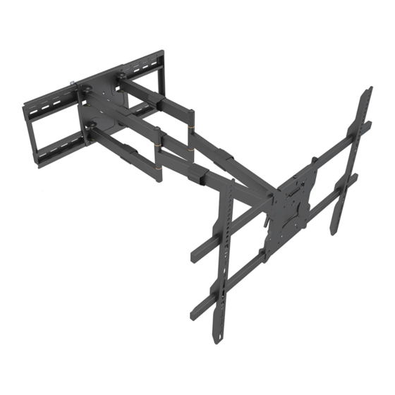
MI-394
Full Motion TV Wall Mount With
Long Extension Dual Arms
100x100.200x200.300x300.
400x200.400x400
600x400.800x600
WARNING: This installation manual is intended to provide guidance on how
to install the TV mount and the TV on a suitable wall. Please contact a
quali fi ed professional if you are unsure of the steps described in the manual
or have doubts about the safety of the installation. Improper installation
may cause damage or serious injury. We cannot be held liable for damage
or injury caused by improper mounting, incorrect assembly, inappropriate
use or for use cases not explicitly speci fi ed in this document.
65"-110"
125kg/275lbs
Advertisement
Table of Contents

Related Manuals for Mount-It! MI-394


Summary of Contents for Mount-It! MI-394
- Page 1 MI-394 Full Motion TV Wall Mount With Long Extension Dual Arms 65″-110″ 100x100.200x200.300x300. 125kg/275lbs 400x200.400x400 600x400.800x600 WARNING: This installation manual is intended to provide guidance on how to install the TV mount and the TV on a suitable wall. Please contact a quali fi ed professional if you are unsure of the steps described in the manual or have doubts about the safety of the installation.
- Page 2 CHOKING HAZARD. Package includes small parts. Not for children under 3 years. Adult supervision is required. PACKAGE CONTENTS TV brackets Main Mount Body TV Mounting Hardware Wall Mounting Hardware 8x65 Plastic Anchor Safety Brackets " onry 3/ 8” (1 0 ”...
- Page 3 CAUTION: DO NOT INSTALL ON DRY WALL ALONE. INSTALL MOUNT ON WOOD STUDS. USER MUST VERIFY THE WALL CAN HOLD THE WEIGHT OF THE TV AND THE TV MOUNT. INSTALLATION OPTION 1: Wood Stud Installation (Suitable for 16” or 24” apart studs) 1).
- Page 4 INSTALLATION OPTION 2: Concrete/Brick Wall Installation 1). Attach the Wall Plate Template (BB) to the wall at the desired installation location. 2). Ensure the Wall Plate Template (BB) horizontal alignment is verified with a bubble level and mark 6 lag bolt installation locations on the stencil and the wall. 3).
- Page 5 Take Off Attaching the TV to the Mount (For Displays With Smaller Bolt Hole Patterns) For TVs with smaller bolt hole patterns of VESA 100x100 , 100x200 , 200x100 and 200x200mm, the TV can be mounted directly on the plate, without the extension bars. Remove the screws Take off the rails 200(7.8”)
- Page 6 Attaching the TV to the Mount (For Displays With Larger Bolt Hole Patterns) For TVs with larger bolt hole patterns of VESA 300x300,400x200,400x400,600x400, 800x600 mm, use the TV brackets and the extension bars to install the TV to the mount. A+E or B+E or C+E or D or G Attach the 2 x TV Brackets to the back of theTV by using screws A+E or B+E or C+E or D or G.
- Page 7 Secure the TV brackets on the mount by attaching the 4 x AA Safety Brackets with 4 x F Screws as shown on the image. NOTE: Failure to secure the TV brackets to the mount with AA Safety Brackets may result in accidental lift off of the TV from the extension bars, possibly resulting in bodily or property damage.
- Page 8 Use the integrated cable management clips on the arms to route cables to the back or side of the TV. Cable Dimensions 110mm [4.3″ ] 825mm [32.5″ ]Max φ8.3mm [φ0.3″ ] 200mm [7.9″ ] 100mm [3.9″ ] ±5° 980mm [38.6″ ] 690mm [27.2″...
Need help?
Do you have a question about the MI-394 and is the answer not in the manual?
Questions and answers