Table of Contents
Advertisement
Available languages
Available languages
Quick Links
Установка и сборка:
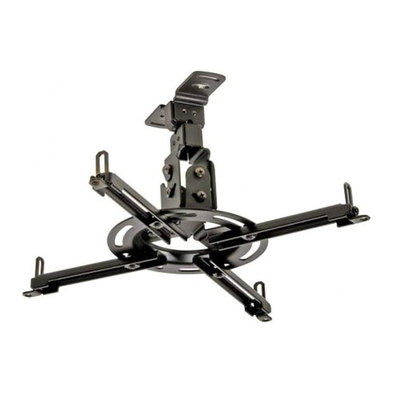
Paramount™ – Скрытый потолочный кронштейн
: I-PPF, I-PPF-S
Характеристики:
• Предоставляет полный объем регулировок изображения:
Наклон: +30/-5°
Поворот: ±20°
Вращение: ±20°
• Плоский дизайн для скрытого крепления к потолку
• Универсальная пластина-переходник Spider® выдвигается
на расстояние от 7,1" (180 mm) до 16,55" (420 mm) для
совместимостью с большинством моделей проекторов.
3215 W. North Ave. • Melrose Park, IL 60160 • (800) 865-2112 or (708) 865-8870 • Fax: (708) 865-2941 • www.peerlessmounts.com
Проектор в
комплект не входит
: 11.09.09 : 055-9496-R-3 30.08.10
Advertisement
Chapters
Table of Contents

Related Manuals for PEERLESS PARAMOUNT I-PPF


Summary of Contents for PEERLESS PARAMOUNT I-PPF
- Page 1 Установка и сборка: Paramount™ – Скрытый потолочный кронштейн : I-PPF, I-PPF-S Проектор в комплект не входит Характеристики: • Предоставляет полный объем регулировок изображения: Наклон: +30/-5° Поворот: ±20° Вращение: ±20° • Плоский дизайн для скрытого крепления к потолку •...
- Page 2 Приступайте к монтажу крепления Peerless только посяе того, как вьl вниматеьно ознакомились с инструкциями и предостережениями. Eсли какие-либо инструкции или предостережения не совем понятньl, позвоните нам по телефону 1-800-865-2112 (для звонков из США) или свяжитесь c местньlм дистрибуторм.
- Page 3 M4 x 10 mm 520-1060 520-2060 J M5 x 10 mm 520-1063 520-2063 K M6 x 10 mm 520-1066 520-2066 540-1025 540-4025 560-9646 560-9646 560-1097 560-1097 3 16 : 11.09.09 : 055-9496-R-3 30.08.10 © 2008, Peerless Industries. ...
-
Page 4: Установка На Потолке Из Деревянных Балок
крепление, как показано на рисунке. БАЛКА ОСЛАБЛЕННЫЙ ВИНТ ПОТОЛОЧНАЯ БАЛКА СКОБА ОТВЕРСТИЕ КРЕПЕЖНЫЕ ВЫСТУП ОТВЕРСТИЯ КРЕПЕЖНЫЕ ОТВЕРСТИЯ ПОДВЕСНАЯ СКОБА ПОДВЕСНАЯ СКОБА СТРЕЛКА УКАЗЫВАЕТ БУДУШЕЕ СТРЕЛКА УКАЗЫВАЕТ БУДУШЕЕ НАПРАВЛЕНИЕ ПРОЕКТОРА НАПРАВЛЕНИЕ ПРОЕКТОРА 4 16 : 11.09.09 : 055-9496-R-3 30.08.10 © 2008, Peerless Industries. ... -
Page 5: Установка На Бетонном Потолке
5 16 : 11.09.09 : 055-9496-R-3 30.08.10 © 2008, Peerless Industries. ... -
Page 6: Крепление Пластины-Переходника К Кронштейну Проектора
крепежных отверстий, не используйте эту пластину-переходник. КРЮКООБРАЗНЫЕ Рис. 3.2 Рис. 3.3 ОТВЕРСТИЯ НАПРАВЛЕНЫ КРЕПЕЖНОЕ В СТОРОНУ ЗАДНЕЙ ОТВЕРСТИЕ СТОРОНЫ ПРОЕКТОРА ОСНОВАНИЕ ШПУНТА ШПУНТ СТАНДАРТНЫЙ ПРОЕКТОР ВИД СВЕРХУ 6 16 : 11.09.09 : 055-9496-R-3 30.08.10 © 2008, Peerless Industries. ... - Page 7 шарнирной/поворотной скобы и шарнирном механизме, как показано ПОДВЕСНАЯ на рисунке 5.3. СКОБА 1/8" 1/8" (3 mm) (3 mm) ВИД СПЕРЕДИ Рис. 5.5 Рис. 5.4 КРЮКООБРАЗНЫЕ ОТВЕРСТИЯ 7 16 : 11.09.09 : 055-9496-R-3 30.08.10 © 2008, Peerless Industries. ...
-
Page 8: Регулировка Проектора
– ВИД СВЕРХУ – ВИД СПЕРЕДИ – ВИД СБОКУ 8 16 : 11.09.09 : 055-9496-R-3 30.08.10 © 2008, Peerless Industries. © 2008, Peerless Industries, Inc. Все права защищены. Все прочие марки и названия являются зарегистрированными торговыми марками их владельцев. - Page 9 Installation and Assembly: Paramount™ Ceiling Flush Mount Models: I-PPF, I-PPF-S Projector not included Features: Provides full range of image adjustment: Tilt: +30/-5° Roll: ±20° Swivel: ±20° Low-profi le design for fl ush mount installations Spider Maximum Load Capacity: universal adapter plate extends from 7.1"...
-
Page 10: Table Of Contents
Note: Read entire instruction sheet before you start installation and assembly. WARNING • Do not begin to install your Peerless product until you have read and understood the instructions and warnings contained in this Installation Sheet. If you have any questions regarding any of the instructions or warnings, please call Peerless customer care at 1-800-865-2112. -
Page 11: Parts List
Before you begin, make sure all parts shown are included with your product. Parts List PPF-S Description Qty. Part # Part # A swivel assembly 055-1877 055-4877 B pivot/roll bracket 055-1810 055-4810 C universal adapter plate 055-1867 055-4867 D #14 x 2.5 wood screw 5S1-015-C03 5S1-015-C04 E Alligator®... -
Page 12: Installation To Wood Joist Ceiling
Installation to Wood Joist Ceiling WARNING • Installer must verify that the supporting surface will safely support the combined load of the equipment and all attached hardware and components. • Tighten wood screws so that bracket is fi rmly attached, but do not overtighten. Overtightening can damage the screws, greatly reducing their holding power. -
Page 13: Installation To Solid Concrete Ceiling
Installation to Concrete Ceilings WARNING • Concrete must be 2000 psi density minimum. Lighter density concrete may not hold concrete anchor. • Installer must verify that the supporting surface will safely support the combined load of the equipment and all at- tached hardware and components. -
Page 14: Attaching Adapter Plate To Projector Mount
Attaching Adapter Plate to Projector Mount Guide fl anges of pivot/roll bracket (B) under fl anges of adapter plate (C) by rotating 90° as shown in fi gure 2.1. Secure pivot/roll bracket (B) to adapter plate (C) by using two M5 x 10 mm screws (F) and two locknuts (G) as shown in fi... - Page 15 Attaching Adapter Plate to Projector Mount (continued) Attach adapter plate (C) to projector using one screw (H, I, J or K) for each channel as shown. Tighten all screws, while keeping the adapter plate centered. Be sure that adapter plate and pivot/roll bracket (B) are in the correct position.
-
Page 16: Projector Alignment
TILT A D JU S TM EN T TOP VIEW FRONT VIEW SIDE VIEW 16 of 16 ISSUED: 11-09-09 SHEET #: 055-9496-R-3 30.08.10 © 2008, Peerless Industries, Inc. All rights reserved. All other brand and product names are trademarks or registered trademarks of their respective owners.
Need help?
Do you have a question about the PARAMOUNT I-PPF and is the answer not in the manual?
Questions and answers