
Related Manuals for PEERLESS PSMU-PRS


Summary of Contents for PEERLESS PSMU-PRS
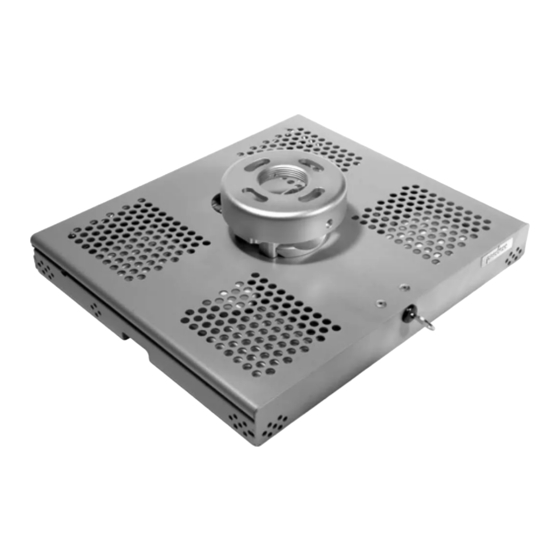
- Page 1 Installation and Assembly: Tray Style Projector Mount Models: PSMU-PRS, PSMU-PRS-S, PSMU-PRS-W Max Load Capacity: 30 lb (13.6 kg)
- Page 2 Note: Read entire instruction sheet before you start installation and assembly. WARNING • Do not begin to install your Peerless product until you have read and understood the instructions and warnings contained in this Installation Sheet. If you have any questions regarding any of the instructions or warnings, please call Peerless customer service at 1-800-729-0307.
- Page 3 IMPORTANT! Read entire instruction sheet before you start installation and assembly. Before you start check the parts list below to make sure all of the parts shown are included. Parts List Description Qty. PSMU-PRS PSMU-PRS-S PSMU-PRS-W A projector mount assembly 055-0420...
- Page 4 Disengage connection block from projector mount assembly (A) by unscrewing captive screw and sliding out connection block as shown. CONNECTION BLOCK CAPTIVE SCREW Remove the lock plug (C) by turning the key counterclockwise. Open the top cover, attach connection block to tray (B) using two #10-32 x 3/8"...
-
Page 5: Installation To Wood Joist Finished Ceilings, Exposed Wood Joists, Or Wood Beam Ceilings
Installation To Wood Joist Finished Ceilings, Exposed Wood Joists, or Wood Beam Ceilings Drill two 5/32" (4 mm) dia. holes to a minimum depth of 2.5" (64 mm). Attach projector mount assembly (A) with two #14 x 2.5" (6 mm x 65 mm) wood screws (V) and two flat washers (I) as shown in figure 1 or figure 2 depending on joist orientation. -
Page 6: Installation To Concrete Ceilings
Installation to Concrete Ceilings Drill two 1/4" (6 mm) dia. holes to a minimum depth of 2.5" (64 mm). Attach projector mount assembly (A) using two concrete anchors , two flat washers (I), and two #14 x 2.5" wood screws as shown in Illustration A and 1, 2, and 3 (below). -
Page 7: Installation To Extension Column
Installation to Threaded Rod Attach projector mount assembly (A) to two 3/8-16 threaded rods (not included) using two 3/8-16 hex thin nylon- insert locknuts (not included) as shown in figure 1.1 or figure 1.2. Skip to step 4. 3/8 -16 THREADED ROD 3/8 -16 THREADED ROD (NOT INCLUDED) (NOT INCLUDED) -
Page 8: Installation Of Projector
Open the mount and remove thumb screw as shown. Note: The upper tray of the mount will now slide off of the lower tray. THUMB SCREW Installation of Projector SCREW Flip projector upside down. Attach lower tray to the bottom of the projector using appropriate number of screws (K,L,M,N,O,P,Q,R,S) , washers (I) and spacers (F) as shown. - Page 9 Slide upper tray into the lower tray as shown. UPPER TRAY LOWER TRAY Attach thumb screw to mount as shown to lock the upper tray to the lower tray. UPPER TRAY LOWER TRAY THUMB SCREW...
- Page 10 Close the mount and insert the lock plug (C) and key (X) as shown. Turn lock plug clockwise until tightly secure. Note: To remove key , key slot must be in the horizontal position. This may require that you back off 1/4 turn. IMPORTANT: Key is neccesary for projector removal.
- Page 11 IMPORTANT: For security installations, insert one #10-32 socket pin screw (Y) through projector mount assembly (A) and into connection block as shown. To adjust yaw (swivel) for wood stud, concrete ceiling, and threaded rod mounting applications: Loosen wood screws (V), or locknuts for threaded rods, until projector mount can be rotated. Rotate mount to desired position and retighten screws or locknuts.
Need help?
Do you have a question about the PSMU-PRS and is the answer not in the manual?
Questions and answers