Table of Contents
Advertisement
Quick Links
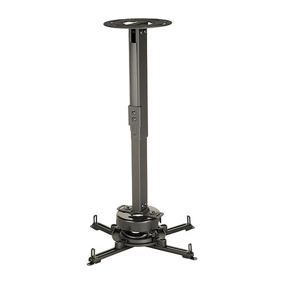
Installation and Assembly:
Projector Ceiling/Wall Mount
Models: PRS-EXA, PRS-EXA-S, PRS-EXA-W
PRS-EXB, PRS-EXB-S, PRS-EXB-W
PRS-EXC, PRS-EXC-S, PRS-EXC-W
Features:
• Continuous channel design for uninterrupted drop length or wall extension adjustments
• Safety catch designed into extension to ensure user and equipment safety
• Internal cable management within channels for clean, clutter-free appearance
• Includes PRS Series projector mount for precise image alignment
Visit the Peerless Web Site at www.peerlessmounts.com
3215 W. North Ave. • Melrose Park, IL 60160 • (800) 865-2112 or (708) 865-8870 • Fax: (708) 865-2941 • www.peerlessmounts.com
Installed to
Ceiling
1 of 13
R
Maximum UL Load Capacity:
Installed to Wall
(PRS-EXC models are not
wall mountable due to its
extensive reach)
ISSUED: 04-24-08 SHEET #: 055-9256-1
For customer care call 1-800-865-2112 or 708-865-8870.
This product is intended for use with UL
Listed products and must be installed by a
qualified professional installer.
25 lb (11.3 kg)
Advertisement
Table of Contents

Related Manuals for PEERLESS PRS-EXA


Summary of Contents for PEERLESS PRS-EXA
- Page 1 1 of 13 ISSUED: 04-24-08 SHEET #: 055-9256-1 Visit the Peerless Web Site at www.peerlessmounts.com For customer care call 1-800-865-2112 or 708-865-8870. 3215 W. North Ave. • Melrose Park, IL 60160 • (800) 865-2112 or (708) 865-8870 • Fax: (708) 865-2941 • www.peerlessmounts.com...
-
Page 2: Table Of Contents
Note: Read entire instruction sheet before you start installation and assembly. WARNING • Do not begin to install your Peerless product until you have read and understood the instructions and warnings contained in this Installation Sheet. If you have any questions regarding any of the instructions or warnings, please call Peerless customer care at 1-800-865-2112. -
Page 3: Parts List
19.14" - 32.9" 055-1770 055-1769 055-1809 PRS-EXC-S 19.14" - 32.9" 055-4770 055-4769 055-4809 PRS-EXC-W 19.14" - 32.9" 055-2770 055-2769 055-2809 3 of 13 ISSUED: 04-24-08 SHEET #: 055-9256-1 Visit the Peerless Web Site at www.peerlessmounts.com For customer care call 1-800-865-2112 or 708-865-8870. - Page 4 Note: Actual parts may appear slightly different than illustrated. 4 of 13 ISSUED: 04-24-08 SHEET #: 055-9256-1 Visit the Peerless Web Site at www.peerlessmounts.com For customer care call 1-800-865-2112 or 708-865-8870.
-
Page 5: Installing Outer Channel To Ceiling Plate
M6 x 10 mm socket pin screws (II) as shown. Tighten screws with 4 mm security wrench (L). 5 of 13 ISSUED: 04-24-08 SHEET #: 055-9256-1 Visit the Peerless Web Site at www.peerlessmounts.com For customer care call 1-800-865-2112 or 708-865-8870. -
Page 6: Installation To Wood Joist Ceiling Or Wood Stud Wall
MOUNTING SLOTS ALLOW FOR ROTATION BEFORE SECURING TO JOIST OPENING ON OUTER CHANNEL (BB) INDICATES FRONT OF MOUNT 6 of 13 ISSUED: 04-24-08 SHEET #: 055-9256-1 Visit the Peerless Web Site at www.peerlessmounts.com For customer care call 1-800-865-2112 or 708-865-8870. -
Page 7: Installation To Solid Concrete Ceiling Or Concrete/Cinder Block Walls
WARNING • When installing Peerless wall mounts on cinder block, verify that you have a minimum of 1-3/8" of actual concrete thickness in the hole to be used for the concrete anchors. Do not drill into mortar joints! Be sure to mount in a solid part of the block, generally 1"... -
Page 8: Installing Inner Channel And Routing Cables
(EXCEPT FOR PRS-EXC MODELS) fig. 3.1 fig. 3.3 OPENING fig. 3.2 HOLES OPENING HOLES GUIDE CABLES IN CHANNELS fig. 3.4 8 of 13 ISSUED: 04-24-08 SHEET #: 055-9256-1 Visit the Peerless Web Site at www.peerlessmounts.com For customer care call 1-800-865-2112 or 708-865-8870. -
Page 9: Installing Projector Mount
(JJ) as shown in figure 5.2. fig. 5.1 fig. 5.2 HOLE INDICATES FRONT OF MOUNT 9 of 13 ISSUED: 04-24-08 SHEET #: 055-9256-1 Visit the Peerless Web Site at www.peerlessmounts.com For customer care call 1-800-865-2112 or 708-865-8870. -
Page 10: Attaching Adapter Plate To Projector
Note: Once channels are in position retighten fasteners. *Notch indicates front of projector. Channel Foot of Channel Mounting hole Generic Projector 10 of 13 ISSUED: 04-24-08 SHEET #: 055-9256-1 Visit the Peerless Web Site at www.peerlessmounts.com For customer care call 1-800-865-2112 or 708-865-8870. - Page 11 (A). EE or FF FRONT OF MOUNT FRONT OF MOUNT CONNECTION BLOCK CAPTIVE SCREW 11 of 13 ISSUED: 04-24-08 SHEET #: 055-9256-1 Visit the Peerless Web Site at www.peerlessmounts.com For customer care call 1-800-865-2112 or 708-865-8870.
-
Page 12: Projector Alignment
• Do not loosen adjustment screws to the point they become disengaged from the mount. Weight of the projector should be supported in case of accidental disengagement. 12 of 13 ISSUED: 04-24-08 SHEET #: 055-9256-1 Visit the Peerless Web Site at www.peerlessmounts.com For customer care call 1-800-865-2112 or 708-865-8870. -
Page 13: Adjusting Mount Extension
ISSUED: 04-24-08 SHEET #: 055-9256-1 Visit the Peerless Web Site at www.peerlessmounts.com For customer care call 1-800-865-2112 or 708-865-8870. © 2008, Peerless Industries, Inc. All rights reserved. All other brand and product names are trademarks or registered trademarks of their respective owners.
Need help?
Do you have a question about the PRS-EXA and is the answer not in the manual?
Questions and answers