
Related Manuals for PEERLESS PSM-UNV


Summary of Contents for PEERLESS PSM-UNV
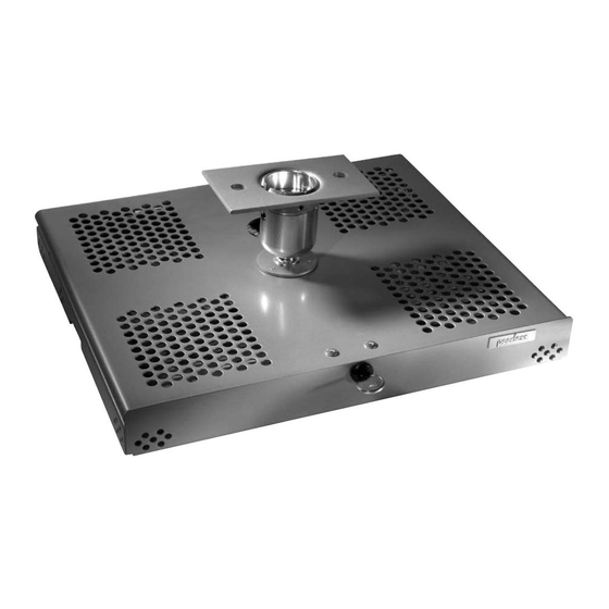
- Page 1 Installation and Assembly: Tray Style Projector Mount Models: PSM-UNV, PSM-UNV-S, PSM-UNV-W This product is UL Listed. It must be installed by a qualified professional installer. Maximum UL Load Capacity: 50 lb (22.7 kg)
- Page 2 Note: Read entire instruction sheet before you start installation and assembly. WARNING • Do not begin to install your Peerless product until you have read and understood the instructions and warnings contained in this Installation Sheet. If you have any questions regarding any of the instructions or warnings, please call Peerless customer service at 1-800-729-0307.
- Page 3 IMPORTANT! Read entire instruction sheet before you start installation and assembly. Before you start check the parts list below to make sure all of the parts shown are included. Parts List Description Qty. PSM-UNV PSM-UNV-S PSM-UNV-W A tray assembly 055-0724...
-
Page 4: Installation To Wood Joist Finished Ceilings, Exposed Wood Joists, Or Wood Beam Ceilings
Installation To Wood Joist Finished Ceilings, Exposed Wood Joists, or Wood Beam Ceilings Drill two 5/32" (4 mm) dia. holes to a minimum depth of 2.5" (64 mm). Attach ceiling plate (Y) with two #14 x 2.5" (6 mm x 65 mm) wood screws (U) as shown using 3/8" (10 mm) socket wrench. Skip to step 2 WARNING •... -
Page 5: Installation To Concrete Ceilings
WARNING • When installing Peerless wall mounts on concrete, verify that you have a minimum of 1 5/8" of actual concrete surface in the 1/4" diameter hole to be used for the concrete anchors. Do not drill into mortar joints! Concrete must meet ASTM C-90 specifications. -
Page 6: Installation To Extension Column
Installation to Extension Column Thread tray assembly (A) into cord management (B) to extension column (sold separately) as shown. Note: Slotted set screw (X) is used to jam against threads of extension column to prevent any excess movement of projector mount assembly (A). Skip to step 2 1 1/2"... -
Page 7: Installation Of Projector
Attaching Top Tray Thread tilting mechanism of top tray into ceiling plate (Y). Align the notch with one of the four holes of the ceiling plate (Y) and secure tilting mechanism with a M5 x 10 mm socket pin screw (W) using 4mm security allen wrench (R) as shown in detail 3. - Page 8 Slide upper tray into the lower tray as shown. UPPER TRAY LOWER TRAY WARNING • Do not lift more weight than you can handle! Use UPPER additional man power or mechanical lifting equipment TRAY to safely handle placement of the projector! Attach thumb screw to mount as shown to lock the upper tray to the lower tray.
- Page 9 Close the mount and insert the lock plug (S) and key (Z) as shown. Note: To remove key, slot must be in the horizontal position. This may require that you back off 1/4 turn. IMPORTANT: Key is neccesary for projector removal. Store it in a safe place. To adjust roll, pitch, and yaw loosen the set screw (shown below) using security allen wrench (R) or standard 4 mm allen wrench.
Need help?
Do you have a question about the PSM-UNV and is the answer not in the manual?
Questions and answers