Table of Contents
Advertisement
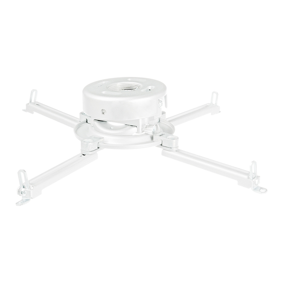
Installation and Assembly Manual:
PRS, RTR Series Projector Mount
Models: PRS-UNV, PRS-UNV-S, PRS-UNV-W
PRS-UNVP, PRS-UNVP-S, PRS-UNVP-W
RTR-UNB, RTR-UNS, RTR-UNW
3215 W. North Ave. • Melrose Park, IL 60160 • (800) 865-2112 or (708) 865-8870 • Fax: (708) 865-2941 • www.peerlessmounts.com
Visit the Peerless Web Site at www.peerlessmounts.com
1 of 12
For customer care call 1-800-729-0307 or 708-865-8870.
This product is intended for use with UL
Listed products and must be installed by a
R
qualified professional installer.
Maximum UL Load Capacity:
25 lb (11.34 kg)
ISSUED: 09-19-05 SHEET #: 055-9441-5 10-31-08
Advertisement
Table of Contents

Related Manuals for PEERLESS PRS-UNV


Summary of Contents for PEERLESS PRS-UNV
- Page 1 Installation and Assembly Manual: PRS, RTR Series Projector Mount Models: PRS-UNV, PRS-UNV-S, PRS-UNV-W PRS-UNVP, PRS-UNVP-S, PRS-UNVP-W RTR-UNB, RTR-UNS, RTR-UNW This product is intended for use with UL Listed products and must be installed by a qualified professional installer. Maximum UL Load Capacity: 25 lb (11.34 kg) 1 of 12 ISSUED: 09-19-05 SHEET #: 055-9441-5 10-31-08...
-
Page 2: Table Of Contents
Note: Read entire instruction sheet before you start installation and assembly. WARNING • Do not begin to install your Peerless product until you have read and understood the instructions and warnings contained in this Installation Sheet. If you have any questions regarding any of the instructions or warnings, please call Peerless customer care at 1-800-865-2112. -
Page 3: Parts List
Before you start check the parts list to insure all of the parts shown are included. PRS-UNV, PRS-UNV-S, PRS-UNV-W, Parts List PRS-UNVP PRS-UNVP-S PRS-UNVP-W RTR-UNB RTR-UNS RTR-UNW Description Qty. Part # Part # Part # projector mount assembly (non-security adjustments) 055-0607 055-0608 055-0609... -
Page 4: Installation To Extension Columns / Ceiling Plate
Installation to Extension Column / Ceiling Plate NOTE: Refer to accompanying instructions with ceiling plates (sold separately) for installing these models to ceiling. Screw projector mount assembly (A) onto extension column as shown in figure 1.1. NOTE: For 3/4" extension columns, reducer ACC 913 will be required as shown in figure 1.2. Tighten swivel stop screw against extension column, flush mount tube or reducer using 4 mm security t-wrench (L) as shown in figure 1.3. -
Page 5: Installation To Wood Joist Ceilings
Installation To Wood Joist Ceilings WARNING • Installer must verify that the supporting surface will safely support the combined load of the equipment and all attached hardware and components. • Tighten wood screws so that projector mount assembly is firmly attached, but do not overtighten. Overtightening can damage the screws, greatly reducing their holding power. -
Page 6: Installation To Concrete Ceilings
Installation to Concrete Ceilings WARNING • Concrete must be 2000 psi density minimum. Lighter density concrete may not hold concrete anchor. • Make sure that the supporting surface will safely support the combined load of the equipment and all attached hard- ware and components. -
Page 7: Installation To Threaded Rods
Installation to Threaded Rod (Not evaluated by UL - Professional installation only) Thread two 3/8-16 hex thin nylon-insert locknuts (not included) on two 3/8-16 threaded rods (not included) to the desired height of projector mount assembly. Attach projector mount assembly (A) to the two 3/8-16 threaded rods using two 3/8-16 hex thin nylon-insert locknuts as shown in figure 4.1 or figure 4.2. -
Page 8: Attaching Adapter Plate To Projector
Attaching Adapter Plate to Projector Note: The projector you are installing may differ in appearance from the sample illustrated below. Place projector upside down. Locate adapter plate (B) with notch facing forward as close to projector center of gravity as possible without covering any mounting holes. Loosen channels with 4 mm security t-wrench (L), and if there are only three mounting holes remove fourth channel. - Page 9 Attaching Adapter Plate to Projector (continued) WARNING • Always use an assistant or mechanical lifting equipment to safely lift and position the projector. Slide connection block with projector into projector mount assembly (A) as shown. Push in and tighten captive screw to secure projector to projector mount assembly (A).
-
Page 10: Projector Alignment
Projector Alignment To adjust yaw (swivel) for threaded rod mounting applications: Loosen locknuts on threaded rods (refer to step four), until projector mount can be rotated. Rotate mount to desired position and retighten screws or locknuts. To adjust yaw (swivel) for extension column applications: Loosen screw on projector mount assembly (A) indicated below until projector mount can be rotated. -
Page 11: Accessories
PRS Series Projector Mount Accessories Ceiling Plates Truss Ceiling Adapter ® Escutcheon Ring Unistrut Adapter : ACC 557* : ACC 640 : ACC 550 ODEL ODEL ODEL 250 lbs. (113.4 kg.) 250 lbs. (113.4 kg.) • Covers hole where extension Black Black OLOR... -
Page 12: Accessories
ISSUED: 09-19-05 SHEET #: 055-9441-5 10-31-08 Visit the Peerless Web Site at www.peerlessmounts.com For customer care call 1-800-729-0307 or 708-865-8870. © 2008, Peerless Industries, Inc. All rights reserved. All other brand and product names are trademarks or registered trademarks of their respective owners.
Need help?
Do you have a question about the PRS-UNV and is the answer not in the manual?
Questions and answers