Advertisement
Quick Links
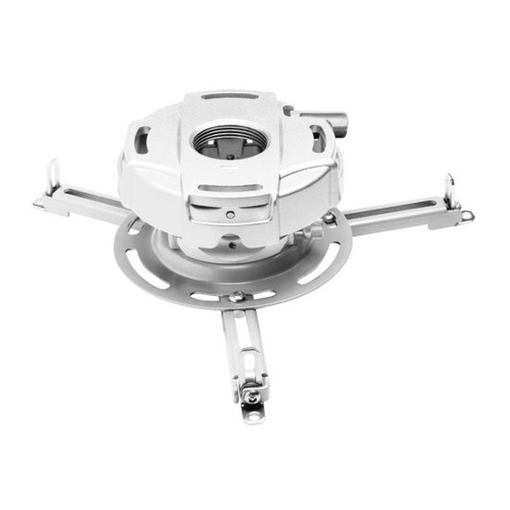
Installation and Assembly:
PRG Precision Gear Projector Mount with
Universal Adapter Plate
Models: PRG-UNV, PRG-UNV-S, PRG-UNV-W
U L
C
US
©
Max Load Capacity: 50 lb (22.7 kg)
Features:
• ImageLockTM alignment prevents picture sag or drift
• Exclusive aluminum track quick release
ISSUED: 09-30-09 SHEET #: 056-9024-3 05-13-10
Advertisement

Related Manuals for PEERLESS PRG-UNV-S


Summary of Contents for PEERLESS PRG-UNV-S
- Page 1 Installation and Assembly: PRG Precision Gear Projector Mount with Universal Adapter Plate Models: PRG-UNV, PRG-UNV-S, PRG-UNV-W © Max Load Capacity: 50 lb (22.7 kg) Features: • ImageLockTM alignment prevents picture sag or drift • Exclusive aluminum track quick release ISSUED: 09-30-09 SHEET #: 056-9024-3 05-13-10...
- Page 2 NOTE: Read entire instruction sheet before you start installation and assembly. WARNING • Do not begin to install your Peerless product until you have read and understood the instructions and warnings contained in this Installation Sheet. If you have any questions regarding any of the instructions or warnings, for US customers please call Peerless customer care at 1-800-865-2112, for all international customers, please contact your local distributor.
-
Page 3: Parts List
Before you start check the parts list to insure all of the parts shown are included. Parts List PRG-UNV PRG-UNV-S PRG-UNV-W Description Qty. Part # Part # Part # projector mount assembly 055-1968 055-4968 055-2968 adapter plate 055-1938 055-4938 055-2838... -
Page 4: Projector Mount Assembly Installation
Installation to Extension Column / Ceiling Plate NOTE: Refer to accompanying instructions with ceiling plates (sold separately) for installing these models to ceiling. Screw projector mount assembly (A) onto extension column as shown in fi gure 1.1. Tighten swivel stop screw against extension column, fl ush mount tube or reducer using 4 mm security allen wrench (I) as shown in fi... - Page 5 Installation To Wood Joist Ceilings WARNING • Installer must verify that the supporting surface will safely support the combined load of the equipment and all attached hardware and components. • Tighten wood screws so that wall plate is fi rmly attached, but do not overtighten. Overtightening can damage the screws, greatly reducing their holding power.
- Page 6 Installation To Concrete Ceilings WARNING • Concrete must be 2000 psi density minimum. Lighter density concrete may not hold concrete anchor. • Make sure that the wall will safely support four times the combined load of the equipment and all attached hardware and components.
- Page 7 WARNING • Always attach concrete expansion anchors directly to load-bearing concrete. • Never attach concrete expansion anchors to concrete covered with plaster, drywall, or other fi nishing material. If mounting to concrete surfaces covered with a fi nishing surface is unavoidable (Not Evaluated By UL), the fi...
- Page 8 Installation to Threaded Rod (Not evaluated by UL - Professional installation only) Thread two 1/4-20 hex thin nylon-insert locknuts (not included) on two 1/4-20 threaded rods (not included) to the desired height of projector mount assembly. Attach projector mount assembly (A) to the two 1/4-20 threaded rods using two 1/4-20 hex thin nylon-insert locknuts as shown in fi...
-
Page 9: Attaching Adapter Plate To Projector
Attaching Adapter Plate to Projector NOTE: The projector you are installing may differ in appearance from the sample illustrated below. Place projector upside down. Locate adapter plate (B) with notch facing forward as close to projector center of gravity as possible without covering any mounting holes. Loosen channels with 4 mm security allen wrench (I), and if there are only three mounting holes remove fourth channel. - Page 10 Attach adapter plate (B) to projector using one screw (J, K, L or M) for each channel as shown below. Tighten all screws, while keeping the center of gravity. Be sure that adapter plate (B) is straight. Adjust the feet of the channels to keep the adapter plate level. Tighten all screws with 4 mm security allen wrench (I) while keeping the center of gravity.
- Page 11 WARNING • Always use an assistant or mechanical lifting equipment to safely lift and position the projector. Slide connection block with projector into projector mount assembly (A) as shown. Push in and tighten captive screw to secure projector to projector mount assembly (A). ARROW INDICATES FRONT OF MOUNT CONNECTION BLOCK...
- Page 12 Cable Management To make an opening to route cables through fi g. 9.1 projector mount assembly, adjust projector CABLES WITH NOTE: INNER mount assembly to full upward tilt position COMBINATION OF VGA DIAMETER OF by turning knob for tilt adjustment as shown CONNECTOR EXTENSION COLUMN AND RCA PLUGS...
- Page 13 Projector Alignment To adjust yaw (swivel) for threaded rod mounting applications: Loosen locknuts for threaded rods (refer to step four) until projector mount can be rotated. Rotate mount to desired position and retighten locknuts. To adjust yaw (swivel) for extension column applications: Loosen screw on projector mount assembly (A) indicated below until projector mount can be rotated.
- Page 14 To prevent tampering with the pitch and roll adjustments: Tighten the two tamper resistant security screws on the projector mount assembly using 4 mm security allen wrench (I) to lock the pitch and roll adjustments as shown below. NOTE: Tighten screws fi rmly, but do not overtighten. Overtightening can damage the mount. WARNING •...
-
Page 15: Accessories
PRG Series Projector Mount Accessories Ceiling Plates Truss Ceiling Adapter ® Escutcheon Ring Unistrut Adapter : ACC 557* : ACC 550 : ACC 640 ODEL ODEL ODEL 250 lbs. (113.4 kg.) 250 lbs. (113.4 kg.) • Covers hole where extension Black Black OLOR... - Page 16 PRG Series Projector Mount Accessories Cord Management • Includes, four, 2' sections Cord Wrap • Designed to externally route cords along the : ACC 852(W)(S)* ODELS outside of an 1/2" extension column • Sections can be stacked to create longer lengths Black, White, or Silver OLOR or cut to desired length...
Need help?
Do you have a question about the PRG-UNV-S and is the answer not in the manual?
Questions and answers