Table of Contents
Advertisement
These instructions are intended for professional garage door
opener installers.
All references are taken from inside looking out.
DOC#
161083_01
RELEASED:
15/12/22
www.bnd.com.au
Smart Pro, Smart
& Secure
Sectional Door Opener
installation instructions
Smart Pro, Smart & Secure
(SDO-9V3, SDO-7V3 & SDO-6V3)
Advertisement
Table of Contents


Need help?
Do you have a question about the Smart Pro SDO-9V3 and is the answer not in the manual?
Questions and answers
My wifi button the the smart hub is flashing red & blue, and no longer connecting to my phone app. Pressing the yellow mode button keeps bypassing the wifi light. Is there a way to completely reboot the unit so I can reconnect to my wifi?
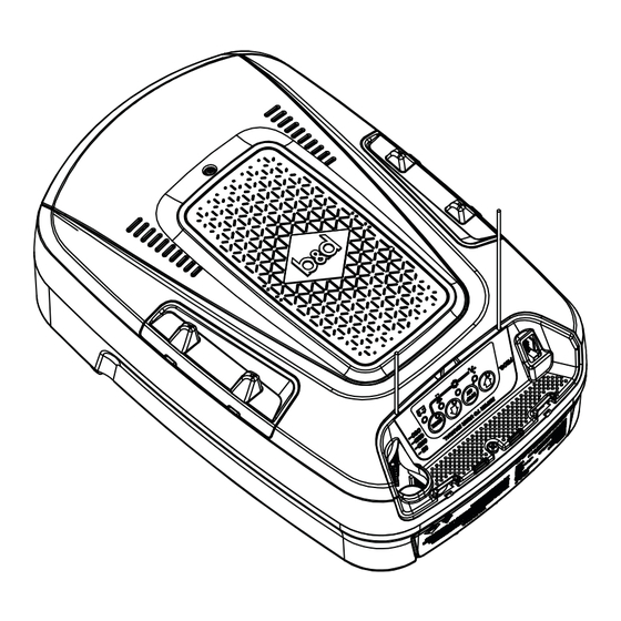
To reboot the B&D SDO-9V3 Smart Hub and reconnect it to Wi-Fi:
1. Remove the controls cover.
2. Press the network button repeatedly until the LED turns purple (Hotspot On).
3. Open the app on your phone.
4. Go to Wi-Fi settings and connect to the network labeled (B&D000000).
5. Return to the app and select "Set up new Smart Hub."
6. Follow the instructions in the app.
7. The Network LED will flash, turn blue, and then stop when connected.
If needed, the device may also show alternating LEDs during reboot.
This answer is automatically generated