Rockwell Automation Allen-Bradley Kinetix 350 Migration Manual
Hide thumbs
Also See for Allen-Bradley Kinetix 350:
- Installation instructions manual (20 pages) ,
- Installation instructions manual (16 pages) ,
- Selection manual (234 pages)
Table of Contents
Advertisement
Kinetix 350 to Kinetix 5300
Servo Drive Migration Guide
Catalog Numbers 2198-C1004-ERS, 2198-C1007-ERS, 2198-C1015-ERS, 2198-C1020-ERS,
2198-C2030-ERS, 2198-C2055-ERS, 2198-C2075-ERS, 2198-C4004-ERS, 2198-C4007-ERS,
2198-C4015-ERS, 2198-C4020-ERS, 2198-C4030-ERS, 2198-C4055-ERS, 2198-C4075-ERS
Reference Manual
Original Instructions
Advertisement
Table of Contents

Related Manuals for Rockwell Automation Allen-Bradley Kinetix 350


Summary of Contents for Rockwell Automation Allen-Bradley Kinetix 350
- Page 1 Kinetix 350 to Kinetix 5300 Servo Drive Migration Guide Catalog Numbers 2198-C1004-ERS, 2198-C1007-ERS, 2198-C1015-ERS, 2198-C1020-ERS, 2198-C2030-ERS, 2198-C2055-ERS, 2198-C2075-ERS, 2198-C4004-ERS, 2198-C4007-ERS, 2198-C4015-ERS, 2198-C4020-ERS, 2198-C4030-ERS, 2198-C4055-ERS, 2198-C4075-ERS Reference Manual Original Instructions...
- Page 2 If this equipment is used in a manner not specified by the manufacturer, the protection provided by the equipment may be impaired. In no event will Rockwell Automation, Inc. be responsible or liable for indirect or consequential damages resulting from the use or application of this equipment.
-
Page 3: Table Of Contents
Kinetix 350 Power Wiring Diagrams......37 Kinetix 5300 Power Wiring Diagrams ......40 Rockwell Automation Publication 2198-RM005A-EN-P - October 2020... - Page 4 Feature Comparison ..........51 Rockwell Automation Publication 2198-RM005A-EN-P - October 2020...
-
Page 5: Preface
See the Kinetix Servo Drives Specifications Technical Data, publication KNX-TD003 for complete specifications. Studio 5000 Logix Designer application is used to configure and program both Application Conversion the Kinetix 350 and Kinetix 5300 drives. Rockwell Automation Publication 2198-RM005A-EN-P - October 2020... -
Page 6: Additional Resources
GMC-RM001 electrical noise. Industrial Automation Wiring and Grounding Guidelines, publication 1770-4.1 Provides general guidelines to install a Rockwell Automation industrial system. Product Certifications website: rok.auto/certifications Provides declarations of conformity, certificates, and other certification details. You can view or download publications at rok.auto/literature. -
Page 7: Replacement Considerations
Verify that the drive size is compatible. • Verify that the drive dimensions are compatible with your available installation space. • Verify that the drive connections and connector wires are all labeled prior to disconnecting the old connectors. Rockwell Automation Publication 2198-RM005A-EN-P - October 2020... -
Page 8: Catalog Number Explanation
The Kinetix 5300 drives with similar current ratings require a similar physical space compared to the Kinetix 350 drives. Factors that affect the redesign effort include these considerations: • Drive sizing (ratings and physical) • Dimension comparison • Drive interconnects and cabling • Accessories Rockwell Automation Publication 2198-RM005A-EN-P - October 2020... -
Page 9: Drive Replacement
6.0 (8.5) 2198-C4007-ERS 2.9 (4.1) 9.3 (13.2) 342…528V, three-phase 2097-V34PR5-LM 4.0 (5.7) 12.0 (17.0) 2198-C4015-ERS three-phase 5.2 (7.4) 18.0 (25.5) (480V nom) (480V nom) 2097-V34PR6-LM 6.0 (8.5) 18.0 (25.5) 2198-C4020-ERS 7.3 (10.3) 23.8 (33.7) Rockwell Automation Publication 2198-RM005A-EN-P - October 2020... -
Page 10: Dimension Comparison
55 (2.16) 200 (7.87) 2097-V34PR6-LM 238 (9.37) 68.0 (2.68) 230 (9.06) 2198-C4020-ERS 265 (10.43) 55 (2.16) 200 (7.87) (1) Height includes connectors. Refer to Dimensions, Cables, and Wiring for additional information on dimensions. Rockwell Automation Publication 2198-RM005A-EN-P - October 2020... -
Page 11: Ac Input Power Cable Length And Fuse Protection
Kinetix 5300 drive connectors. Table 5 - Input and Motor Power Connection Placement for Kinetix 350 and Kinetix 5300 Drives Series Input Power Location Motor Power Location Kinetix 350 Front Kinetix 5300 Bottom Rockwell Automation Publication 2198-RM005A-EN-P - October 2020... -
Page 12: Circuit Breaker And Fuse Considerations
Three-phase KTK-R-12 140U-D6D3-B80 1489-M3C100 140U-D6D3-B80 2198-C4020-ERS 480V Three-phase KTK-R-15 140U-D6D3-C12 1489-M3C130 140U-D6D3-C12 2198-C4030-ERS 480V Three-phase KTK-R-25 140U-D6D3-C15 1489-M3C200 140U-D6D3-C15 2198-C4055-ERS 480V Three-phase LPJ-30SP 140U-D6D3-C30 1489-M3C350 140U-D6D3-C30 2198-C4075-ERS 480V Three-phase LPJ-35SP 140U-D6D3-C30 1489-M3C400 140U-D6D3-C30 Rockwell Automation Publication 2198-RM005A-EN-P - October 2020... -
Page 13: Power Specifications
(2) Peak RMS current allowed for up to 2 seconds with a 50% duty cycle. (3) Nominal continuous power output (kW) applies to 240V AC drives. Value is approximately one-half of this kW rating when using 120V AC. Rockwell Automation Publication 2198-RM005A-EN-P - October 2020... - Page 14 17.3 A 35.4 A Nom 230V input (single-phase) 13.4 A 21.9 A 29.0 A 57.4 A Nom 230V input (three-phase) 13.4 A 21.9 A 41.3 A 57.4 A Line loss ride through 20 ms Rockwell Automation Publication 2198-RM005A-EN-P - October 2020...
- Page 15 (3) For current values when motors include a holding brake, refer to Kinetix Servo Drive Specifications Technical Data, publication KNX-TD003. (4) Peak RMS current allowed for up to 1.0 seconds. (5) This rating is only valid if UL specified fuses are used. Rockwell Automation Publication 2198-RM005A-EN-P - October 2020...
- Page 16 (3) For current values when motors include a holding brake, refer to Kinetix Servo Drive Specifications Technical Data, publication KNX-TD003. (4) Peak RMS current allowed for up to 1.0 seconds. (5) This rating is only valid if UL specified fuses are used. Rockwell Automation Publication 2198-RM005A-EN-P - October 2020...
-
Page 17: I/O Availability And Specifications
Specifications consistent. Digital Inputs This section describes digital inputs for Kinetix 350 and Kinetix 5300 servo drives. Table 15 compares the digital inputs of the two drive families. Rockwell Automation Publication 2198-RM005A-EN-P - October 2020... - Page 18 IOD-27 NEG_OT single-ended active high signal. Current loading is nominally 1 ms Level IOD-28 POS_OT 9 mA per input. The positive/negative limit switch (normally closed contact) inputs for axis require 24V DC (nominal). Rockwell Automation Publication 2198-RM005A-EN-P - October 2020...
- Page 19 Figure 2 - Sinking of Digital Inputs 1.2 kΩ ENABLE, HOME_SW, POS_OT, or NEG_OT 1.2 kΩ ENABLE, HOME_SW, POS_OT, or NEG_OT +24V Figure 3 - Sourcing of Registration Digital Input 1.2 kΩ +24V 1.2 kΩ REG_COM Rockwell Automation Publication 2198-RM005A-EN-P - October 2020...
-
Page 20: Motor Brake Output
The customer-supplied 24V power supply drives the brake output through a solid-state relay. Rockwell Automation Publication 2198-RM005A-EN-P - October 2020... - Page 21 Figure 6 - Motor Brake Circuit 24V PWR INT PWR Control Board MBRK+ (BC-1) Inductive ISP772 Energy Kinetix 5300 Clamp Servo Drive MBRK– (BC-2) 24V COM IMPORTANT Motor parking-brake switching frequency must not exceed 15 cycles/min. Rockwell Automation Publication 2198-RM005A-EN-P - October 2020...
-
Page 22: Control And Auxiliary Power Specifications
Kinetix 5300 safety inputs. The National Electrical Code and local electrical codes take precedence over the values and methods provided. Implementation of these codes is the responsibility of the machine builder. Rockwell Automation Publication 2198-RM005A-EN-P - October 2020... -
Page 23: Kinetix Motor And Actuator Compatibility
The Kinetix 350 drives support multiple types of feedback devices by using the 15-pin (MF) motor feedback connector and shared connector pins in many cases. The drive accepts motor feedback signals from encoders with these general specifications. Rockwell Automation Publication 2198-RM005A-EN-P - October 2020... -
Page 24: Accessories
Kinetix 350 drives in Kinetix 5300 applications. Dimensions, Cables, and Wiring for more details. In some instances, existing shunt resistors used with Kinetix 350 drives can be reused with Kinetix 5300 drives. Rockwell Automation Publication 2198-RM005A-EN-P - October 2020... -
Page 25: Required Accessories
(1) Refer to the Kinetix Servo Drives Specifications Technical Data, publication KNX-TD003, for detailed descriptions and specifications of these drive accessories. (2) Where x equals the cable length in meters. (3) This is an optional accessory. Rockwell Automation Publication 2198-RM005A-EN-P - October 2020... -
Page 26: Optional Drive Accessories
When using an external Ethernet switch for routing traffic between the controller and the drive, switches with IEEE-1588 time synchronization capabilities (boundary or transparent clock) must be used to make sure switch delays are compensated. Rockwell Automation Publication 2198-RM005A-EN-P - October 2020... -
Page 27: Connectors
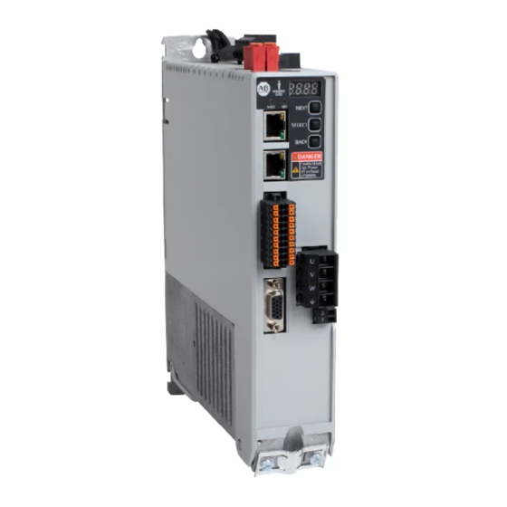
Network status indicator Back-up power (BP) connector Module status indicator Display control push buttons (3) Axis status indicator Motor power (MP) connector Ethernet communication port (Port 1) Safe torque-off (STO) connector I/O (IOD) connector Rockwell Automation Publication 2198-RM005A-EN-P - October 2020... -
Page 28: Kinetix 5300 Servo Drive Connector Locations
Kinetix 5300 drive. There is no separate auxiliary feedback connector used with the Kinetix 350 or Kinetix 5300 drives. The auxiliary encoder signal is wired using the I/O connector. Rockwell Automation Publication 2198-RM005A-EN-P - October 2020... - Page 29 Overtravel detection is available as an optically isolated, single-ended active high signal. IOD-27 NEG_OT Current loading is nominally 9 mA per input. The positive/negative limit switch (normally closed 1 ms Level IOD-28 POS_OT contact) inputs for axis require 24V DC (nominal). Rockwell Automation Publication 2198-RM005A-EN-P - October 2020...
-
Page 30: Motor Feedback
Drives User Manual, publication 2198-UM005 for additional information on supported feedback types. Figure 9 - 15 Pin Motor Feedback Connector Pin Assignment Pin 10 Pin 15 Pin 5 Pin 11 Pin 1 Pin 6 Rockwell Automation Publication 2198-RM005A-EN-P - October 2020... -
Page 31: Safe Torque Off Connector
Kinetix 350 drive safe torque-off (STO) connector. The Kinetix 5300 10-pin connector consists of two parallel 5-pin rows for cascading safety connections from drive-to-drive when drives are joined by the zero-stack feature. Rockwell Automation Publication 2198-RM005A-EN-P - October 2020... - Page 32 Safety bypass minus signal. Connect to safety common to disable the STO function 3 and 8 STO input 1 (SS_IN_CH0) 4 and 9 STO input common (SCOM) 5 and 10 STO input 2 (SS_IN_CH1) Rockwell Automation Publication 2198-RM005A-EN-P - October 2020...
-
Page 33: Dimensions, Cables, And Wiring
230 (9.04) 68.0 (2.68) 2097-V32PR2-LM 230 (9.04) 69.0 (2.70) 2097-V32PR4-LM 230 (9.04) 87.0 (3.42) 2097-V33PR1-LM 185 (7.29) 68.0 (2.68) 2097-V33PR3-LM 185 (7.29) 69.0 (2.70) 2097-V33PR5-LM 185 (7.29) 94.0 (3.72) 2097-V33PR6-LM 230 (9.04) 68.0 (2.68) Rockwell Automation Publication 2198-RM005A-EN-P - October 2020... - Page 34 2198-C2075-ERS 2198-C4075-ERS The 2198-K53CK-D15M feedback connector kit is available for Kinetix 5300 servo drives when flying-lead cable are used. Refer to Kinetix 5300 Feedback Connector Kit Installation Instructions, publication 2198-IN023 for more information. Rockwell Automation Publication 2198-RM005A-EN-P - October 2020...
- Page 35 (10.43) 2090-CTFB-MxDD Feedback Cable Frame 3 clamping plate for large diameter cables. (3.94) (11.81) Clearance required for drive-end cable (3.15) connectors apply to all frame sizes. 2090-CFBM7DD-CEAxxx Feedback Cable (drive-end connector) (1.89) (9.76) Rockwell Automation Publication 2198-RM005A-EN-P - October 2020...
-
Page 36: Cables
MPAS-A/Bxxxx-ALMx2C (direct drive) linear 30 (98.4) TLY-Axxxx-B Tamagawa (17-bit) absolute high- TL-Axxxx-B resolution, multi-turn TLY-Axxxx-H Incremental encoder Hiperface, absolute, LDAT-Sxxxxxx-xDx magnetic scale Incremental, magnetic LDAT-Sxxxxxx-xBx 10 (33.1) scale Sin/Cos or TTL LDC-Cxxxxxx-xH, LDL-xxxxxxx-xH encoder Rockwell Automation Publication 2198-RM005A-EN-P - October 2020... -
Page 37: Power Wiring
Kinetix 5300 drives. Factory-made motor power and feedback cables with premolded connectors are designed to minimize electromagnetic interference (EMI). Rockwell Automation recommends factory-made cables to achieve the expected system performance. For details and drawings of recommended cables see the Kinetix Motion... - Page 38 Figure 16 - Single-phase Grounded Power Configurations 2097-V32PRx-LM Transformer Secondary 2097-V31PRx-LM Kinetix 350 Drives AC Line Single-phase AC Input 240V AC Filter L2/N Output Input Fusing Contactor Bonded Cabinet Ground Bus Ground Grid or Power Distribution Ground Rockwell Automation Publication 2198-RM005A-EN-P - October 2020...
- Page 39 The supply voltage swing can cause undervoltage and overvoltage trips on the drives, and the drive can be damaged if the overvoltage limit is exceeded. Rockwell Automation Publication 2198-RM005A-EN-P - October 2020...
-
Page 40: Kinetix 5300 Power Wiring Diagrams
Kinetix 5300 Power Wiring Diagrams For Kinetix 5300 drive power specifications, see Kinetix Servo Drives Specifications Technical Data, publication KNX-TD003. For Kinetix 5300 drive interconnect diagrams, see Kinetix 5300 Single-axis EtherNet/IP Servo Drives, publication 2198-UM005. Rockwell Automation Publication 2198-RM005A-EN-P - October 2020... - Page 41 Bonded Cabinet Ground Ground Stud Ground Grid or Power Distribution Ground ATTENTION: Ungrounded systems do not reference each phase potential to a power distribution ground. This can result in an unknown potential to earth ground. Rockwell Automation Publication 2198-RM005A-EN-P - October 2020...
- Page 42 Chapter 3 Dimensions, Cables, and Wiring Notes: Rockwell Automation Publication 2198-RM005A-EN-P - October 2020...
-
Page 43: System Architecture
Feedback Connector Kit 2090-K2CK-D15M Low-profile connector kit for motor feedback signals. (1) See Encoder Output Module Installation Instructions, publication 2198-UM003. For information to help you install and wire the 2198-ABQE Encoder Output Module. Rockwell Automation Publication 2198-RM005A-EN-P - October 2020... - Page 44 Supply 2097-R6 and 2097-R7 External Shunt Bulletin 2097 and 2198 external passive shunt resistors are available for when the internal shunt capability of the drive is 2198-R001, 2198-R002, Resistors exceeded. 2198-R004, 2198-R014, 2198-R031 Rockwell Automation Publication 2198-RM005A-EN-P - October 2020...
-
Page 45: Kinetix 350 Servo Drive System Architecture
2097-F1 Filter Shown 24V DC Control Back-up 2097-TB1 Terminal Power Supply Expansion Block (optional equipment) 2090-K2CK-D15M Low-profile Connector Kit Bulletin 2090 Bulletin 2090 Motor Feedback Cables Motor Power Cables Motor Refer to Table 35 Rockwell Automation Publication 2198-RM005A-EN-P - October 2020... -
Page 46: Kinetix 5300 Drive Hardware And Input Power Configurations
Allen-Bradley 1606-XL and Motor Brake Power Power Supply (customer-supplied) Input AC Input Power 2198-C -ERS Drive (front view) MBRK Bulletin 2090 Motor Power Cables Bulletin 2090 Motor Motor Feedback Cables Refer to Table Rockwell Automation Publication 2198-RM005A-EN-P - October 2020... - Page 47 -ERS Drives (front view) MBRK MBRK Bulletin 2090 Motor Power Cables Bulletin 2090 Motor Feedback Cables Motor Refer to Table Bulletin 2090 Bulletin 2090 Motor Feedback Cables Motor Power Cables Motor Refer to Table Rockwell Automation Publication 2198-RM005A-EN-P - October 2020...
-
Page 48: Typical Communication Configurations
EtherNet/IP network. Refer to CompactLogix 5380, Compact GuardLogix 5380, and CompactLogix 5480 Controller Specifications Technical Data, publication 5069-TD002, for more information on CompactLogix 5380 controllers. Rockwell Automation Publication 2198-RM005A-EN-P - October 2020... - Page 49 System EtherNet/IP Adapter Power Field Power Link 2 Activity/ Status 842E-CM Integrated Kinetix 5300 Servo Drive System Motion Encoder 1585J-M8CBJM-OM15 0.15 m (6 in.) Ethernet cable for drive-to-drive connections. MBRK MBRK MBRK MBRK Rockwell Automation Publication 2198-RM005A-EN-P - October 2020...
- Page 50 MBRK MBRK PanelView Plus 7 – Display Terminal 1734-AENTR POINT I/O EtherNet/IP Adapter See Kinetix 5300 Single-axis EtherNet/IP Servo Drives, publication 2198-UM005 for additional motor and auxiliary feedback connection and communication topology configurations. Rockwell Automation Publication 2198-RM005A-EN-P - October 2020...
-
Page 51: Feature Comparison
Dual Loop Control Dual-port Ethernet with DLR support (1) Refer to Replacement Considerations: Figure 1…Figure 4 for more information. (2) Only via interposing relay. (3) Directly drive up to, 2.25A or via interposing relay. Rockwell Automation Publication 2198-RM005A-EN-P - October 2020... - Page 52 Kinetix 350 to Kinetix 5300 Servo Drive Migration Guide Notes: Rockwell Automation Publication 2198-RM005A-EN-P - October 2020...
- Page 53 Rockwell Automation Publication 2198-RM005A-EN-P - October 2020...
- Page 54 Allen-Bradley, Compact GuardLogix, CompactLogix, Connected Components Workbench, ControlLogix, expanding human possibility, Kinetix, Logix 5000, MicorLogix, PanelView, POINT I/O, Rockwell Automation, Rockwell Software, RSLogix 5000, SLC, Stratix, and Studio 5000 Logix Designer are trademarks of Rockwell Automation, Inc. EtherNet/IP is a trademark of ODVA, Inc.
Need help?
Do you have a question about the Allen-Bradley Kinetix 350 and is the answer not in the manual?
Questions and answers