Table of Contents
Advertisement
Quick Links
Advertisement
Table of Contents
Troubleshooting

Subscribe to Our Youtube Channel
Related Manuals for Rockwell Automation Allen-Bradley Kinetix 300 2097-V31PR0


Summary of Contents for Rockwell Automation Allen-Bradley Kinetix 300 2097-V31PR0
- Page 1 Kinetix 300 EtherNet/IP Indexing Servo Drives Catalog Numbers 2097-V31PR0, 2097-V31PR2, 2097-V32PR0, 2097-V32PR2, 2097-V32PR4, 2097-V33PR1, 2097-V33PR3, 2097-V33PR5, 2097-V33PR6, 2097-V34PR3, 2097-V34PR5, 2097-V34PR6 User Manual Original Instructions...
- Page 2 If this equipment is used in a manner not specified by the manufacturer, the protection provided by the equipment may be impaired. In no event will Rockwell Automation, Inc. be responsible or liable for indirect or consequential damages resulting from the use or application of this equipment.
-
Page 3: Table Of Contents
Buffered Encoder Outputs ....... . . 46 Rockwell Automation Publication 2097-UM001F-EN-P - December 2022... - Page 4 Input/Output Categories ........91 Rockwell Automation Publication 2097-UM001F-EN-P - December 2022...
- Page 5 Configure the Logix Controller ......131 Rockwell Automation Publication 2097-UM001F-EN-P - December 2022...
- Page 6 STO Connector Pinouts ........165 Wiring Your Safe Torque Off Circuit......166 Rockwell Automation Publication 2097-UM001F-EN-P - December 2022...
- Page 7 Overtravel Fault Recovery........222 Rockwell Automation Publication 2097-UM001F-EN-P - December 2022...
- Page 8 ............227 Rockwell Automation Publication 2097-UM001F-EN-P - December 2022...
-
Page 9: Preface
Rockwell Automation sales representative for information on available training courses. Rockwell Automation recognizes that some of the terms that are currently used in our industry and in this publication are not in alignment with the movement toward inclusive language in technology. We are proactively collaborating with industry peers to find alternatives to such terms and making changes to our products and content. -
Page 10: Additional Resources
Preface Additional Resources These documents contain additional information concerning related products from Rockwell Automation. You can view or download publications at rok.auto/literature. Resource Description Kinetix Rotary Motion Specifications Technical Data, publication KNX-TD001 Product specifications for Kinetix VPL, VPC, VPF, VPH, and VPS; Kinetix MPL, MPM, MPF, and MPS;... -
Page 11: About The Kinetix 300 Drive System
Compatible stages include Kinetix MPAS integrated linear stages. Linear Actuators Kinetix LDAT Compatible actuators include Kinetix LDAT integrated linear thrusters. Linear Motors Kinetix LDC and LDL Compatible linear motors include Kinetix LDC and LDL linear motors. Rockwell Automation Publication 2097-UM001F-EN-P - December 2022... - Page 12 Kinetix MP and Kinetix TL Electric Cylinders (MPAR-Bxxxx electric cylinders shown) Kinetix MP Heavy-Duty Electric Cylinders (MPAI-Bxxxx electric cylinders shown) Kinetix LDC Linear Motors Kinetix LDL Linear Motors (LDC-Cxxxxxxx linear motor shown) (LDL-xxxxxxx linear motor shown) Rockwell Automation Publication 2097-UM001F-EN-P - December 2022...
-
Page 13: Catalog Number Explanation
Table 5 - Kinetix 300 Drive Accessories Cat. No. Drive Components 2097-Fx AC line filters 2097-TB1 Terminal block for I/O connector 2097-Rx Shunt resistors 2097-PGMR Memory module programmer 2097-MEM Memory modules 12 pack Rockwell Automation Publication 2097-UM001F-EN-P - December 2022... -
Page 14: Agency Compliance
Use shielded cable for power wiring and provide a grounded 360° clamp termination. See Appendix A on page 173 for interconnect diagrams, including input power wiring and drive/motor interconnect diagrams. Rockwell Automation Publication 2097-UM001F-EN-P - December 2022... - Page 15 Metal debris or other foreign matter can become lodged in the circuitry, which can result in damage to components. Rockwell Automation Publication 2097-UM001F-EN-P - December 2022...
-
Page 16: System Design Guidelines
IMPORTANT System performance was tested at these cable length specifications. These limitations are also a CE requirement. See the System Design for Control of Electrical Noise Reference Manual, publication GMC-RM001, for a better understanding the concept of electrical noise reduction. Rockwell Automation Publication 2097-UM001F-EN-P - December 2022... -
Page 17: Transformer Selection
See the Kinetix 3, 300, 350, 2000, 6000, 6200, 6500, 7000 Servo Drives Specifications Technical Data, publication KNX-TD005, for input current and inrush current specifications for your Kinetix 300 drive. Fuse and Circuit Breaker (CB) Specifications page 18 recommended circuit breakers and fuses. Rockwell Automation Publication 2097-UM001F-EN-P - December 2022... - Page 18 For 140M to 140MT device migration details, see Bulletin 140M to 140MT Motor Protection Circuit Breakers Migration Profile, publication MIGRAT-PP049. (2) For UL applications, Bulletin 140M and 140MT devices are applied as self-protected combination motor controllers. Rockwell Automation Publication 2097-UM001F-EN-P - December 2022...
-
Page 19: Enclosure Selection
Because this cabinet size is considerably larger than what is necessary to house the system components. The choice of a smaller cabinet than can be more efficient to cool. Contact your cabinet manufacturer for options available to cool your cabinet. Rockwell Automation Publication 2097-UM001F-EN-P - December 2022... -
Page 20: Power Dissipation Specifications
Use this table to size an enclosure and calculate required ventilation for your Kinetix 300 drive system. Cat. No. Power Dissipation, W 2097-V31PR0 2097-V31PR2 2097-V32PR0 2097-V32PR2 2097-V32PR4 2097-V33PR1 2097-V33PR3 2097-V33PR5 2097-V33PR6 2097-V34PR3 2097-V34PR5 2097-V34PR6 Rockwell Automation Publication 2097-UM001F-EN-P - December 2022... -
Page 21: Minimum Clearance Requirements
Side Clearance Side Clearance 2097-V33PR1 185 (7.29) 2097-V33PR3 185 (7.29) 2097-V33PR5 185 (7.29) 2097-V33PR6 230 (9.04) 2097-V34PR3 185 (7.29) 25.0 mm (1.0 in.) Clearance 2097-V34PR5 185 (7.29) for Airflow and Installation 2097-V34PR6 230 (9.04) Rockwell Automation Publication 2097-UM001F-EN-P - December 2022... -
Page 22: Electrical Noise Reduction
Improper bonding of the metal surfaces blocks the direct return path and allows high-frequency energy to travel elsewhere in the cabinet. Excessive high- frequency energy can affect the operation of other microprocessor-controlled equipment. Rockwell Automation Publication 2097-UM001F-EN-P - December 2022... - Page 23 Flat Washer Star Washer Flat Washer If the mounting bracket is coated with a non-conductive material (anodized Star Washer or painted), scrape the material around the mounting hole. Rockwell Automation Publication 2097-UM001F-EN-P - December 2022...
-
Page 24: Bonding Multiple Subpanels
Wire Braid. 25.4 mm (1.0 in.) by 6.35 mm (0.25 in.) Ground bus that is bonded to the subpanel. Wire Braid. Remove paint 25.4 mm (1.0 in.) by from cabinet. 6.35 mm (0.25 in.) Rockwell Automation Publication 2097-UM001F-EN-P - December 2022... -
Page 25: Establishing The Noise Zones
(3) This is a clean 24V DC available for any device that requires it. The 24V enters the clean wireway and exits to the left. (4) This is a dirty 24V DC available for motor brakes and contactors. The 24V enters the dirty wireway and exits to the right. Rockwell Automation Publication 2097-UM001F-EN-P - December 2022... - Page 26 (3) This is a clean 24V DC available for any device that requires it. The 24V enters the clean wireway and exits to the left. (4) This is a dirty 24V DC available for motor brakes and contactors. The 24V enters the dirty wireway and exits to the right. Rockwell Automation Publication 2097-UM001F-EN-P - December 2022...
-
Page 27: Cable Categories For Kinetix 300 Drive Components
Kinetix 300 drive, and as close to the drive as possible. • Good HF bonding to the panel is critical. For painted panels, see the examples on page • Isolate input and output wiring as far as possible. Rockwell Automation Publication 2097-UM001F-EN-P - December 2022... - Page 28 (2) When space does not permit 150 mm (6.0 in.) clearance, install a grounded steel shield between the drive and clean wireway. For examples, see the System Design for Control of Electrical Noise Reference Manual, publication GMC-RM001. Rockwell Automation Publication 2097-UM001F-EN-P - December 2022...
- Page 29 The brake is mounted inside the motor and how you connect to the drive depends on the motor series. Kinetix 300 Drive/Rotary Motor Wiring Examples beginning on page 178 for the interconnect diagram of your drive/motor combination. Rockwell Automation Publication 2097-UM001F-EN-P - December 2022...
-
Page 30: Mount Your Kinetix 300 Drive
1.1 N•m (9.8 lb•in). Observe bonding techniques as described in Bonding Drives page IMPORTANT To improve the bond between the Kinetix 300 drive and subpanel, construct your subpanel out of zinc plated (paint-free) steel. 3. Tighten all mounting fasteners. Rockwell Automation Publication 2097-UM001F-EN-P - December 2022... - Page 31 Chapter Kinetix 300 Drive Connector Data and Feature Descriptions Topic Page Kinetix 300 Drive Connectors and Indicators Control Signal Specifications Motor Feedback Specifications Rockwell Automation Publication 2097-UM001F-EN-P - December 2022...
-
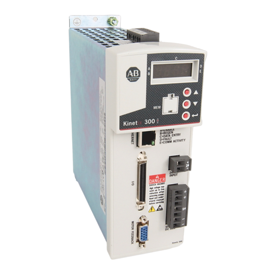
Page 32: Kinetix 300 Drive Connectors And Indicators
15-pin high-density D-shell (male) Back-up power 2-pin quick-connect terminal block Shunt Resistor and DC Bus 7-pin quick-connect terminal block Motor power 6-pin quick-connect terminal block Safe Torque Off (STO) terminal 6-pin quick-connect terminal block Rockwell Automation Publication 2097-UM001F-EN-P - December 2022... -
Page 33: Safe Torque Off Connector Pinout
IMPORTANT Use Pins STO-1 (+24V DC Control) and STO-2 (Control COM) only for the motion-allowed jumpers to defeat the Safe Torque Off function. When the Safe Torque Off function is in operation, the 24V supply must come from an external source. Rockwell Automation Publication 2097-UM001F-EN-P - December 2022... -
Page 34: I/O Connector Pinout
Programmable output #3 emitter OUT3-E Positive travel limit switch IN_A2 Programmable output #4 collector OUT4-C Inhibit/enable input IN_A3 Programmable output #4 emitter OUT4-E Figure 11 - Pin Orientation for 50-pin SCSI I/O (IOD) Connector Rockwell Automation Publication 2097-UM001F-EN-P - December 2022... -
Page 35: Motor Feedback (Mf) Connector Pinout
Transmit Port (-) Data Terminal - TX Receive Port (-) Data Terminal - RX Receive Port (+) Data Terminal + RX — — — — — — Figure 13 - Pin Orientation for 8-pin Ethernet Communication Port Rockwell Automation Publication 2097-UM001F-EN-P - December 2022... -
Page 36: Ac Input Power Connector Pinout
Shunt Resistor and DC Bus Connector Pinout BC Designator Description Signal Positive DC bus/Shunt resistor Shunt Resistor Negative DC bus Motor-Power Connector Pinout MP Designator Description Signal Protective Earth (ground) Motor power out Motor power out Motor power out Rockwell Automation Publication 2097-UM001F-EN-P - December 2022... -
Page 37: Control Signal Specifications
You can configure the inputs that are listed as N/A for any of these functions. • Abort Homing • Abort Index • Start Homing • Start Index • Fault Reset • Home Sensor • Index Select Rockwell Automation Publication 2097-UM001F-EN-P - December 2022... - Page 38 Table 12 - Enable Truth Table (configured for Inhibit) Drive Input Value Enable Input Drive Enable bit in Output Assembly Move to On Move to Off – Resulting Drive State Enabled Disabled Disabled Rockwell Automation Publication 2097-UM001F-EN-P - December 2022...
- Page 39 Start Motion Bit in Output Assembly Abort Index Input (digital I/O from MotionView software) Abort Index (from Output Image) Drive Status Indexing TIP The drive must be enabled for homing and indexing mode. Rockwell Automation Publication 2097-UM001F-EN-P - December 2022...
- Page 40 Table 15 page 41. You can configure the inputs for PNP sourcing or NPN sinking. Figure 18 - Sourcing of Digital Inputs 1.2 k +24V IN_A1 1.2 k IN_A2 IN_A_COM Rockwell Automation Publication 2097-UM001F-EN-P - December 2022...
- Page 41 1.2 k IN_A2 IN_A_COM +24V Table 15 - Digital Input Signal Specifications Parameter Value Scan time 500 µs Current, max 9 mA, typical Input impedance 1.2 k , typical Voltage range 5…24V DC Rockwell Automation Publication 2097-UM001F-EN-P - December 2022...
-
Page 42: Digital Outputs
Table 16 - Digital Output Signal Specifications Parameter Value Scan time 500 µs Current, max 100 mA Voltage, max 30V DC Figure 20 - Digital Output Circuit Kinetix 300 Drive Logic Power OUT1-C OUT1-E Rockwell Automation Publication 2097-UM001F-EN-P - December 2022... -
Page 43: Analog Reference Input
Analog Common (ACOM) terminal. Table 17 - Analog Signal Input Specifications Parameter Value Scan time 0.0625 ms Current, max Depend on load Input impedance 47 k , typical Voltage range -10…10V DC Rockwell Automation Publication 2097-UM001F-EN-P - December 2022... -
Page 44: Analog Output
Table 18 - Analog Output Specifications Parameter Value Scan time 0.0625 ms Current, max 10 mA Voltage range -10…10V DC For configuration/setup of the analog outputs, see Configure the Drive Parameters and System Variables beginning on page 145. Rockwell Automation Publication 2097-UM001F-EN-P - December 2022... -
Page 45: Master Gearing/Step And Direction Inputs
Input frequency, max 2 MHz Pulse width 500 ns (negative or positive) 700 Input impedance Figure 24 - Master Gearing/Step and Direction Input Circuit Diagram MA+/STEP+ 600 W MB+/DIR+ 100 W 5.6V MA-/STEP- MB-/DIR- Rockwell Automation Publication 2097-UM001F-EN-P - December 2022... -
Page 46: Buffered Encoder Outputs
If a motor with encoder feedback is being used, the A+, A-, B+, B-, Z+, and Z- signals are passed directly through drive pins IOD-7…IOD-12 with no filtering, up to a speed of 2 MHz. The encoder pass through delay is approximately 100 ns. Rockwell Automation Publication 2097-UM001F-EN-P - December 2022... -
Page 47: Ethernet Connections
BP connector, the logic and communication circuits remain active during a mains input-power loss. Table 21 - 24V DC Back-up Power Specifications Attribute Value Input voltage 20…26V DC Current 500 mA Inrush, max 30 A Rockwell Automation Publication 2097-UM001F-EN-P - December 2022... -
Page 48: Motor Feedback Specifications
(2) 300 mA on the 5V supply with 150 mA on the 9V supply. (3) 275 mA on the 9V supply with no load on the 5V supply. TIP Auto configuration is possible by using the Kinetix 300 drive MotionView OnBoard software for Allen-Bradley® motors. Rockwell Automation Publication 2097-UM001F-EN-P - December 2022... -
Page 49: Motor Feedback Specifications
Figure 25 - Motor Thermostat Interface 6.81 kW 1 kW MTR_TS 0.01 µF Kinetix 300 Drive Table 24 - Motor Thermostat State Specifications State Resistance at TS 500 No Fault Fault 10 k Rockwell Automation Publication 2097-UM001F-EN-P - December 2022... - Page 50 10 W Shaded area indicates components that are part of the circuit, but support other feedback device types (not used for SICK-Stegmann Hiperface support). to UART from UART Kinetix 300 Drive from UART Rockwell Automation Publication 2097-UM001F-EN-P - December 2022...
- Page 51 Shaded area indicates components that are part of the circuit, but support other feedback device types (not used for Generic TTL incremental support). 1 kW AM+ or to AqB Counter 1K W 1 kW AM- or 56 pF 56 pF Rockwell Automation Publication 2097-UM001F-EN-P - December 2022...
- Page 52 2.5 Mbps, 8 data bits, no parity Battery 3.6V, located external to drive in Low Profile connector kit Figure 27 for the Tamagawa 17-bit serial interface schematic. It is identical to the SICK-Stegmann Hiperface (DATA) signals schematic. Rockwell Automation Publication 2097-UM001F-EN-P - December 2022...
-
Page 53: Feedback Power Supply
Current mA Nominal +5V DC EPWR_5V 5.13 5.67 +9V DC EPWR_9V Figure 31 - Pin Orientation for 15-pin Motor Feedback (MF) Connector Pin 10 Pin 15 Pin 5 Pin 11 Pin 1 Pin 6 Rockwell Automation Publication 2097-UM001F-EN-P - December 2022... - Page 54 Chapter 3 Kinetix 300 Drive Connector Data and Feature Descriptions Notes: Rockwell Automation Publication 2097-UM001F-EN-P - December 2022...
-
Page 55: Basic Wiring Requirements
IMPORTANT This section contains common PWM servo system wire configurations, size, and practices that can be used in most applications. National Electrical Code, local electrical codes, special operating temperatures, duty cycles, or system configurations take precedence over the values and methods provided. Rockwell Automation Publication 2097-UM001F-EN-P - December 2022... -
Page 56: Build Your Own Cables
Match your secondary to one of the examples and be certain to include the grounded neutral connection. Table 93 on page 224 on for more information on leakage current. Rockwell Automation Publication 2097-UM001F-EN-P - December 2022... -
Page 57: Three-Phase Power Wired To Three-Phase Drives
Input Fusing Contactor Bonded Cabinet Ground Bus Ground Grid or Power Distribution Ground (1) Leakage current from the line filter, in this configuration, typically is higher than a balanced (center ground) configuration. Rockwell Automation Publication 2097-UM001F-EN-P - December 2022... -
Page 58: Single-Phase Power Wired To Single-Phase Drives
For Kinetix 300 drive power specifications, see the Kinetix 3, 300, 350, 2000, 6000, 6200, 6500, 7000 Servo Drives Specifications Technical Data, publication KNX-TD005. For Kinetix 300 drive-input wiring diagrams, see Power Wiring Examples on page 175. Rockwell Automation Publication 2097-UM001F-EN-P - December 2022... -
Page 59: Isolation Transformer In Grounded Power Configurations
(1) Contactors (MI, M2, and M3) can be optional. For more information, see Understanding the Machinery Directive, publication SHB-900. AC line filter is optional, but is required for CE compliance. Feeder short-circuit protection is not illustrated. Rockwell Automation Publication 2097-UM001F-EN-P - December 2022... - Page 60 Figure 37. The neutral connection applies if three-phase is brought directly into the filter and no isolating transformer is present. Rockwell Automation Publication 2097-UM001F-EN-P - December 2022...
-
Page 61: Voiding Of Ce Compliance
ATTENTION: The three-phase isolation transformer and neutral in-line filter applications that are described in this document have not been tested for EMC by Rockwell Automation and products that are used in such installations are not considered CE Marked by Rockwell Automation. -
Page 62: Ground Your Kinetix 300 Drive System
Ground Strap Ground Bus Ground Stud Ground Grid or Power Distribution Ground For drive dimensions, See the Kinetix 3, 300, 350, 2000, 6000, 6200, 6500, 7000 Servo Drives Specifications Technical Data, publication KNX-TD005. Rockwell Automation Publication 2097-UM001F-EN-P - December 2022... -
Page 63: Ground Multiple Subpanels
AC power is arbitrary and earth ground connection is required for improve safety and proper operation. Power Wiring Examples on page 175 for interconnect diagrams. IMPORTANT The National Electrical Code and local electrical codes take precedence over the values and methods provided. Rockwell Automation Publication 2097-UM001F-EN-P - December 2022... - Page 64 (1) Applies to 2097-V33PRx, and 2097-V34PRx drive modules. (2) Applies to 2097-V31PRx drive modules. (3) Applies to 2097-V32PRx drive modules. (4) Use for shunt resistor connection only. (5) Use for bypassing the STO circuit only. Rockwell Automation Publication 2097-UM001F-EN-P - December 2022...
-
Page 65: Wiring Guidelines
5. Gently pull on each wire to make sure that it does not come out of its terminal; reinsert and tighten any loose wires. 6. Insert the connector plug into the module connector. Rockwell Automation Publication 2097-UM001F-EN-P - December 2022... -
Page 66: Wiring The Kinetix 300 Drive Connectors
Table 30 - Back-up Power (BP) Connector Recommended Strip Length Torque Value Drive Cat. No. Terminals Wire Size mm (in.) N•m (lb•in) (AWG) +24V DC 2097-V3xPRx 1.5 (16) 6 (0.25) 0.5 (4.5) -24V DC Rockwell Automation Publication 2097-UM001F-EN-P - December 2022... -
Page 67: Wire The Input Power (Ipd) Connector
7 (0.28) 0.5 (4.5) 2097-V33PR5 2097-V31PR2 0.56…0.79 6.0 (10) 7 (0.28) 2097-V33PR6 (5.0…7.0) (1) Applies to 2097-V33PRx, and 2097-V34PRx drive modules. (2) Applies to 2097-V31PRx drive modules. (3) Applies to 2097-V32PRx drive modules. Rockwell Automation Publication 2097-UM001F-EN-P - December 2022... -
Page 68: Wire The Motor Power (Mp) Connector
IMPORTANT For Kinetix TL motors, also connect the 152 mm (6.0 in.) termination wire to the closest earth ground. Pigtail Terminations page 69 for more information. Rockwell Automation Publication 2097-UM001F-EN-P - December 2022... - Page 69 KInetix LDC linear motors LDC-Cxxxx — Kinetix LDL linear motors LDL-xxxxxxx — Kinetix LDAT linear motors LDAT-Sxxxxxxxx — Kinetix TL rotary motors TLY-Axxxx 2090-CPWM6DF-16AAxx Circular Plastic 2090-CPBM6DF-16AAxx (standard) (standard) Kinetix TL rotary motors TLAR-Axxxx Rockwell Automation Publication 2097-UM001F-EN-P - December 2022...
- Page 70 Shield Clamp Kinetix 300 Drive The cable shield clamp that is shown in Figure 43 is mounted to the subpanel. Ground and secure the motor power cable in your system following instructions on page Rockwell Automation Publication 2097-UM001F-EN-P - December 2022...
- Page 71 (3) Diode 1N4004 rated 1.0 A @ 400V DC. See Interconnect Diagram Notes beginning on page 174. (4) Exposed shield under clamp and place within 50…75 mm (2…3 in.) of drive, see page 73 for details. Rockwell Automation Publication 2097-UM001F-EN-P - December 2022...
- Page 72 Torque Value Drive Cat. No. Terminals Wire Size mm (in.) N•m (lb•in) (AWG) 2097-V31PR0 2097-V31PR2 2097-V32PR0 2097-V32PR2 2097-V32PR4 2097-V33PR1 2.5 (14) 7 (0.28) 0.5 (4.5) 2097-V33PR3 2097-V33PR5 2097-V34PR3 2097-V34PR5 2097-V34PR6 2097-V33PR6 4.0 (12) Rockwell Automation Publication 2097-UM001F-EN-P - December 2022...
-
Page 73: Apply The Motor-Cable Shield Clamp
5. Clamp the exposed shield to the panel by using the clamp and 2 #6-32 x 1 screws provided. 6. Repeat step 1…step 5 for each Kinetix 300 drive you are installing. Rockwell Automation Publication 2097-UM001F-EN-P - December 2022... -
Page 74: Feedback And I/O Cable Connections
MPF-A/Bxxxx-M/S MPAR-A/B1xxxx and MPAR-A/B2xxxx (series B) 2090-CFBM7DF-CEAAxx or 2090-CFBM7DD-CEAAxx (standard, non-flex) Absolute Linear LDAT-Sxxxxxx-xDx Encoder Feedback 2090-CFBM7DF-CEAFxx 2090-CFBM7DD-CEAFxx (continuous-flex) TLY-Axxxx-B High-resolution encoder Circular 2090-CFBM6DF-CBAAxx TLAR-Axxxxx page 75 Plastic (standard) TLY-Axxxx-H Incremental encoder 2090-CFBM6DD-CCAAxx Rockwell Automation Publication 2097-UM001F-EN-P - December 2022... -
Page 75: Flying-Lead Feedback Cable Pinouts
Table 39 - 2090-CFBM6DF-CBAAxx Feedback Cable High Resolution Incremental Feedback Drive MF Connector Pin TLY-Axxxx-B Connector Pin TLY-Axxxx-H TLAR-Axxxxx BAT+ Reserved BAT+ Reserved DATA+ DATA- Reserved EPWR 5V EPWR 5V ECOM and BAT- ECOM Shield Shield Connector housing Rockwell Automation Publication 2097-UM001F-EN-P - December 2022... -
Page 76: Wiring The Feedback And I/O Connectors
Terminal Expansion Block. See the Kinetix 300 I/O Terminal Expansion Block Installation Instructions, publication 2097-IN005. Figure 46 - Kinetix 300 Drive (IOD connector and terminal block) 2097-TB1 I/O Terminal Expansion Block I/O (IOD) Connector Rockwell Automation Publication 2097-UM001F-EN-P - December 2022... -
Page 77: Wire The Low Profile Connector Kit
Exposed Braid Under Clamp Tie Wrap Turn clamp over to hold small wires secure. Kinetix 2090 Feedback Cable See Low Profile Connector Kit Installation Instructions, publication 2093-IN005, for connector kit specifications. Rockwell Automation Publication 2097-UM001F-EN-P - December 2022... -
Page 78: Shunt Resistor Connections
Front view is shown. Shunt /DC Bus (BC) Connector Table 40 - Shunt-Resistor Power Wiring Requirements Recommended Wire Torque Value Connects to Size Accessory Description N•m (lb•in) Terminals (AWG) 2097-Rx Shunt Resistor 2.5 (14) 0.5 (4.5) Rockwell Automation Publication 2097-UM001F-EN-P - December 2022... -
Page 79: Ethernet Cable Connections
The Port 1 Ethernet connection is used for connecting to a web browser and configuring your Logix module. Figure 51 - Ethernet Wiring Example - External Switch 1783-EMS08T CompactLogix Controller Platform CompactLogix L23E Stratix® 6000 1769-L23E-QB1B Shown Switch Personal Computer Kinetix 300 Drives Rockwell Automation Publication 2097-UM001F-EN-P - December 2022... - Page 80 Chapter 4 Connecting the Kinetix 300 Drive System Notes: Rockwell Automation Publication 2097-UM001F-EN-P - December 2022...
- Page 81 MotionView Software Configuration Topic Page Drive Organizer and Identification Motor Category General Category Communication Categories Input/Output Categories Limits Categories Dynamics Category Tools Category Monitor Category Faults Category Indexing Category Homing Category Upgrade Firmware Rockwell Automation Publication 2097-UM001F-EN-P - December 2022...
-
Page 82: Drive Organizer And Identification
006 in this example Allen-Bradley® motors and actuators with intelligent feedback devices are Motor Category automatically populated into the motor configuration. In this example, the MPL-A1510V-Hxx2 servo motor is attached to the drive. Rockwell Automation Publication 2097-UM001F-EN-P - December 2022... -
Page 83: Synchronous Motor Database
Synchronous>Motor Database. In this example, the MPL-A1510V-Hxx2 motor is configured. Table 42 - Motor Category Parameter Name Description Value/Notes Motor ID Motor serial number (for Rockwell Automation® motor) Motor Model Motor catalog number (for Rockwell Automation motor) Motor Vendor Rockwell Automation Halls Order Hallcode index Range: 0…5... -
Page 84: Linear Motor Database
Resolution (x1) Linear encoder resolution Range: 0.4…40 µm Nominal Drive Bus Voltage Nominal motor-terminal voltage Range: 50…800V Intermittent Current Intermittent current Range: 0…100 A Thermal resistance Range: 0…10000000 C/W Thermal capacitance Range: 0…10000000 W-s/C Rockwell Automation Publication 2097-UM001F-EN-P - December 2022... -
Page 85: General Category
The General category provides access to the basic configuration of motion. The parameters that are displayed depend on the motor type that is chosen in the Motor Category. Figure 52 - General Category for Synchronous Motors Rockwell Automation Publication 2097-UM001F-EN-P - December 2022... - Page 86 (2) These values apply only if the drive is in Velocity mode over EtherNet/IP External Reference. In Indexing mode, the limits within the individual indexes apply. In Positioning mode, over EtherNet/IP External Reference, the limits in the Output Assembly apply. Rockwell Automation Publication 2097-UM001F-EN-P - December 2022...
- Page 87 MotionView Software Configuration Chapter 5 Figure 53 - General Category for Linear Motors Rockwell Automation Publication 2097-UM001F-EN-P - December 2022...
- Page 88 (2) These values apply only if the drive is in Velocity mode over EtherNet/IP External Reference. In Indexing mode, the limits within the individual indexes apply. In Positioning mode, over EtherNet/IP External Reference, the limits in the Output Assembly apply. Rockwell Automation Publication 2097-UM001F-EN-P - December 2022...
-
Page 89: Communication Categories
Mask changes at next powerup. 32-bit value. Default Gateway Ethernet Gateway IP address Address changes at next powerup. 32-bit value. Obtain IP address Use DHCP Checked = Use DHCP service using DHCP Unchecked = Manual Rockwell Automation Publication 2097-UM001F-EN-P - December 2022... -
Page 90: Ethernet/Ip (Cip) Communication
Datalink D for input assembly UserDefinedIntegerReal1 Enable - Output Assembly Datalink A for output assembly UserDefinedIntegerData0 Links Datalink B for output assembly UserDefinedIntegerData1 Datalink C for output assembly UserDefinedIntegerReal0 Datalink D for output assembly UserDefinedIntegerReal1 Rockwell Automation Publication 2097-UM001F-EN-P - December 2022... -
Page 91: Input/Output Categories
2 = In Speed Window motion is allowed to begin (brake is released). 3 = Current Limit 4 = Runtime fault Output 4 Function (OUT4) 5 = Ready 6 = Brake 7 = In position Rockwell Automation Publication 2097-UM001F-EN-P - December 2022... -
Page 92: Analog I/O
Analog Input deadband Analog input #1 deadband. Applied when Range: 0…100 mV used as current or velocity reference Analog Input Offset Analog input #1 offset. Applied when used Range: -10,000…+10,000 mV as current/velocity reference Rockwell Automation Publication 2097-UM001F-EN-P - December 2022... -
Page 93: Limits Categories
At Speed Value in user units/s for the target velocity for which the drive sets the In-Speed Range: -10000…+10000 rpm Window Digital Output (if configured) and the VelocityLockStatus bit in the EtherNet/IP Input Assembly. Rockwell Automation Publication 2097-UM001F-EN-P - December 2022... -
Page 94: Position Limits
If Soft Limits are On, the position that when reached, the drive asserts a Software User units Overtravel fault. Negative Limit User units (1) Soft Limits parameters can only be used in Positioning mode. Rockwell Automation Publication 2097-UM001F-EN-P - December 2022... -
Page 95: Dynamics Category
A 2x factor that is applied to the gains in the velocity loop useful for Range: -16…+4 scaling the gains when using encoders with a high number of counts per revolution. See the Servo Loop diagram on page 96 for more information on these parameters. Rockwell Automation Publication 2097-UM001F-EN-P - December 2022... -
Page 96: Tools Category
Saturation by Sv = 2 (11 + GainScaling) Scalled Current Limit Velocity P-Gain Velocity Feedback Feedback Low-pass Filter Tools Category The tools category provides access to the oscilloscope and digitally monitor drive performance parameters. Rockwell Automation Publication 2097-UM001F-EN-P - December 2022... -
Page 97: Monitor Category
Temperatures > 40 °C (104 °F) ME Counter Master Encoder (ME) input counter-value, reset by writing zero or other value to the Counts parameter. Phase Current Phase current Amps Target Position (EC) Target position Encoder pulses Rockwell Automation Publication 2097-UM001F-EN-P - December 2022... -
Page 98: Faults Category
Clear Fault History Clear the fault history of the drive. Clear Faults Clear the current fault in the drive. (1) Clear Fault History is password protected for quality assurance purposes. You cannot use this function. Rockwell Automation Publication 2097-UM001F-EN-P - December 2022... -
Page 99: Indexing Category
• Index Select 3 = 8 if active, 0 if not. • Index Select 4 = 16 if active, 0 if not. If an Index Select is not assigned to a digital input, the Index Select is considered inactive. Rockwell Automation Publication 2097-UM001F-EN-P - December 2022... - Page 100 (2) Numerical values (0 =, 1=, 2=, for example) for menu choices appear only in explicit messages that are sent when using RSLogix 5000 and RSLogix 500 software or the Logix Designer application. Rockwell Automation Publication 2097-UM001F-EN-P - December 2022...
-
Page 101: Index Type Parameter
Distance, provided the registration sensor input is not detected. If the registration sensor input is detected, the move is adjusted such that the Registration Distance setting determines the end position. Figure 55 - Registration Index Type Registration Registration Distance Position Rockwell Automation Publication 2097-UM001F-EN-P - December 2022... - Page 102 Rotary Absolute mode is only possible when Rotary Unwind mode is configured in the General category. Figure 57 - Rotary Absolute Move 0° 30° 315° 225° Rockwell Automation Publication 2097-UM001F-EN-P - December 2022...
- Page 103 Rotary Shortest Path mode is only possible when Rotary Unwind mode is configured in the General category. Figure 58 - Rotary Shortest Path Absolute Move 0° 30° 315° 225° Rockwell Automation Publication 2097-UM001F-EN-P - December 2022...
- Page 104 Rotary Negative mode is only possible when Rotary Unwind mode is configured in the General category. Figure 60 - Rotary Negative Absolute Move 0° 315° 45° 225° Rockwell Automation Publication 2097-UM001F-EN-P - December 2022...
- Page 105 All thermal protections continue to be active if the specified current exceeds the continuous current rating of the drive or motor. Figure 61 shows an example of a current index. Figure 61 - Current Indexing Dwell Time Time Rockwell Automation Publication 2097-UM001F-EN-P - December 2022...
-
Page 106: Action Parameter
This action immediately moves to the next index as defined by the Next Index parameter. Figure 64 - Example of Next Index Action Dwell time at zero velocity Index 1 Index 2 Position Rockwell Automation Publication 2097-UM001F-EN-P - December 2022... -
Page 107: Start Index
The configuration for Abort Index can be set in the Add-on Profile (AOP) or through MotionView software interface as a digital input. Reset Index Reset Index sets the current index to the Start Index. Rockwell Automation Publication 2097-UM001F-EN-P - December 2022... -
Page 108: Explicit Messages For Indexing
This DINT contains the action that the drive takes once this index is complete. Index Registration Distance This REAL contains the displacement from the registration position the axis moves to if a registration index is used. Rockwell Automation Publication 2097-UM001F-EN-P - December 2022... - Page 109 Table Table 60 - Index Configuration Assembly Example Byte Parameter Value Index Number - Low byte Index Number - Low middle byte Index Number - High middle byte Index Number - High byte Rockwell Automation Publication 2097-UM001F-EN-P - December 2022...
- Page 110 Dwell Velocity Accel Decel Next Index Action Table 62 - ID Tag Numbers for Indexes 16…31 Parameter Name Index Type Move Distance Register Distance Batch Count Dwell Velocity Accel Decel Next Index Action Rockwell Automation Publication 2097-UM001F-EN-P - December 2022...
-
Page 111: Homing Category
113. Home Switch The digital input that is used as a home switch for the Do not assign to A1, A2, A3, or C3 as these inputs appropriate homing method. have predefined functions. Rockwell Automation Publication 2097-UM001F-EN-P - December 2022... -
Page 112: Homing Methods
IMPORTANT All homing methods write to the nonvolatile memory in the drive, which is limited to 1 million write cycles. The drive must not be homed more often than 1 million times. Rockwell Automation Publication 2097-UM001F-EN-P - December 2022... -
Page 113: Immediate Homing
After a power cycle, the drive continues to operate as though it was homed. For absolute homing on motors with absolute encoders, execute an Immediate Home. Rockwell Automation Publication 2097-UM001F-EN-P - December 2022... -
Page 114: Home To Marker
0…11. Inputs A1…A4 are assigned 0…3 respectively; inputs B1…B4 are assigned 4…7 respectively; and inputs C1…C4 are assigned 8…11 respectively. Do not assign to A1, A2, A3, or C3 as these inputs have predefined functions. Rockwell Automation Publication 2097-UM001F-EN-P - December 2022... -
Page 115: Homing Firmware Algorithm
Homing Start Select Homing Method Start Homing Motor with Absolute Encoder? Execute Immediate Home State offset value and set Home Flag. Store motor-serial number for use during next power-up session. Homing Done? Homing Complete Rockwell Automation Publication 2097-UM001F-EN-P - December 2022... -
Page 116: Homing Methods Timing Diagrams
Figure 67 - Homing Methods 7…10 (forward initial move) Index Pulse Home Switch Positive Limit Switch Figure 68 - Homing Methods 11…14 (reverse initial move) Index Pulse Home Switch Positive Limit Switch Rockwell Automation Publication 2097-UM001F-EN-P - December 2022... -
Page 117: Homing Method 23
Upon activating the positive limit switch the axis changes direction (reverse), following the procedure that is detailed in Homing Method but ignoring the initial move in the forward direction. Figure 69 - Homing Method 23 Home Switch Rockwell Automation Publication 2097-UM001F-EN-P - December 2022... -
Page 118: Homing Method 25
(reverse) and continue motion until it sees the rising edge of the homing switch. The axis stops and follows the procedure as detailed Homing Method Figure 70 - Homing Method 25 Home Switch Rockwell Automation Publication 2097-UM001F-EN-P - December 2022... -
Page 119: Homing Method 27
(forward) and continues motion until it sees the rising-edge of the homing switch. The axis stops and follows the procedure as detailed Homing Method Figure 71 - Homing Method 27 Home Switch Rockwell Automation Publication 2097-UM001F-EN-P - December 2022... -
Page 120: Homing Method 29
(A1). Upon activating the negative limit switch, the axis changes direction (forward) following the procedure as detailed in Homing Method 29, but ignoring the initial move in the reverse direction. Figure 72 - Homing Method 29 Home Switch Rockwell Automation Publication 2097-UM001F-EN-P - December 2022... -
Page 121: Homing Method 33
Using this method, the current position is assumed to be the home position. There is no motion of the motor shaft during this procedure. Any offset specified is added to the stored home position. Rockwell Automation Publication 2097-UM001F-EN-P - December 2022... -
Page 122: Upgrade Firmware
Do not turn off power to the computer or the drive. 8. When the upgrade is finished, restart the drive. Access the upgraded MotionView software by entering the drives IP address in a web browser. Rockwell Automation Publication 2097-UM001F-EN-P - December 2022... -
Page 123: Configure And Start Up The Kinetix 300 Drive
Test and Tune the Axis Select Drive Operating Mode Master Gearing Mode Examples Configure the Drive Parameters and System Variables Configure Drive Mode with Explicit Messaging Configure Drive for Linear Motors and Direct Drive Stages Rockwell Automation Publication 2097-UM001F-EN-P - December 2022... -
Page 124: Keypad Input
Ethernet DHCP Configuration: 0=dHCP is disabled; 1=dHCP is enabled. IP_1 First octet of the IP address. IP_2 Second octet of the IP address. IP_3 Third octet of the IP address. IP_4 Fourth octet of the IP address (changeable). Rockwell Automation Publication 2097-UM001F-EN-P - December 2022... -
Page 125: Status Indicators
Yellow status indicator means the drive is in Regeneration mode. Data entry Yellow status indicator flashes when changing. Drive fault Red status indicator illuminates upon a drive fault. Comm activity Green status indicator flashes to indicate communication activity. Rockwell Automation Publication 2097-UM001F-EN-P - December 2022... -
Page 126: Configure The Kinetix 300 Drive Ethernet/Ip Address
DHCP (Dynamic Host Configuration Protocol) enabled server, or you can assign the drive IP address manually (static IP address). Both methods to configure the drives IP address are shown here. Rockwell Automation Publication 2097-UM001F-EN-P - December 2022... -
Page 127: Current Ip Address Ethernet Setting
0. 4. Cycle power to the drive. The change takes effect. When DHCP is disabled and the drive power is cycled, The IP address reverts to the previous static IP address. Rockwell Automation Publication 2097-UM001F-EN-P - December 2022... - Page 128 9. To make changes to take effect, cycle power. The first time that you change an Ethernet parameter, the following dialog box opens. Click OK and cycle power for changes to take effect. Rockwell Automation Publication 2097-UM001F-EN-P - December 2022...
-
Page 129: Configure The Ip Address Automatically (Dynamic Address)
Kinetix 300 drive is the ability to assign the drive a name (text string). This name can then be used to discover the drives IP address and is useful when the drive has its IP address automatically assigned by the server. Rockwell Automation Publication 2097-UM001F-EN-P - December 2022... -
Page 130: Install The Kinetix 300 Add-On Profile
3. Click Download. 4. Scroll down to Add On Profiles and check Select Files. 5. Scroll down and check AOP for 2097 Kinetix 300 Drives v2.01.02. 6. Click Downloads. 7. Continue with the AOP download. Rockwell Automation Publication 2097-UM001F-EN-P - December 2022... -
Page 131: Configuring The Logix Ethernet/Ip Module
Enter the slot where your module resides (leftmost slot = 0). This step applies only for ControlLogix controllers. e. Name the file. 4. Click OK. 5. From the Edit menu, choose Controller Properties. Rockwell Automation Publication 2097-UM001F-EN-P - December 2022... -
Page 132: Configure The Ethernet Port
Configure the Ethernet Port This section applies when the CompactLogix controller, catalog number 1769- L23E-QB1, is used. Follow these steps to configure the Ethernet port. 1. Right-click the embedded 1769-L23E-QB1 Ethernet port and choose Properties. Rockwell Automation Publication 2097-UM001F-EN-P - December 2022... -
Page 133: Configure The Ethernet Module
This section applies when the ControlLogix controller, catalog number 1756- ENET/B, is used. Follow these steps to configure the Ethernet module. 1. Right-click I/O Configuration in the Controller Organizer and choose New Module. The Select Module dialog box opens. Rockwell Automation Publication 2097-UM001F-EN-P - December 2022... -
Page 134: Configure The Kinetix 300 Drive
Enter the slot where your module resides (leftmost slot = 0). 5. Click OK. Configure the Kinetix 300 Drive Follow these steps to configure the Kinetix 300 drive. 1. Right-click the embedded 1769-L23E Ethernet port and choose New Module. Rockwell Automation Publication 2097-UM001F-EN-P - December 2022... - Page 135 Name the module. b. Set the drive Ethernet address. Set the Ethernet address in the software to match the Ethernet address scrolls on the drive. See Current IP Address Ethernet Setting page 127. Rockwell Automation Publication 2097-UM001F-EN-P - December 2022...
-
Page 136: Download The Program
6. Configure the Requested Packet Interval (RPI) for your application. The default setting is 20 ms. Yours could be different. 7. Click Ok. Download the Program After you complete the Logix configuration, you must download your program to the Logix processor. Rockwell Automation Publication 2097-UM001F-EN-P - December 2022... -
Page 137: Apply Power To The Kinetix 300 Drive
Is from (24V DC) back-up power Apply mains input power to the drive (IPD connector) Mains input power Go to step 6 6. Verify that Hardware Enable Input signal IOD connector pin 29 is at Rockwell Automation Publication 2097-UM001F-EN-P - December 2022... -
Page 138: Test And Tune The Axis
5. Apply Enable Input signal (IOD-29) for the axis you are testing. ATTENTION: To avoid personal injury or damage to equipment, apply Enable Input (IOD-29) only to the axis you are testing. 6. Click Start Autophasing. Rockwell Automation Publication 2097-UM001F-EN-P - December 2022... -
Page 139: Tune The Axis
150 Hz. You can configure the filter in the Dynamics category. 7. Click Autotuning. Rockwell Automation Publication 2097-UM001F-EN-P - December 2022... - Page 140 2. Verify that the Enable Input signal is applied to the axis you are testing. 3. Verify the motor feedback is wired as required. 4. Verify the safe torque-off is wired correctly. 5. Return to main step 6 and run the test again. Rockwell Automation Publication 2097-UM001F-EN-P - December 2022...
- Page 141 These filters are configured from the Dynamics view of the MotionView software and their placement within the servo loops are shown in the figure on page Rockwell Automation Publication 2097-UM001F-EN-P - December 2022...
-
Page 142: Select Drive Operating Mode
4. From the Drive Mode pull-down menu, choose your drive mode. Table 66 - Available Drive Modes Mode Drive Object Value Auto Tune EtherNet/IP External Reference Master Gearing Step and Direction Analog Velocity Input Analog Current Input Indexing Rockwell Automation Publication 2097-UM001F-EN-P - December 2022... -
Page 143: Master Gearing Mode Examples
The drive interpolated counts are 262,144 counts/rev x 5 motor rev/1 output gear box revolution. The master encoder is 2048 x 4 (8192) counts/rev. The [Master] parameter is 1 and the [System] parameter is 262,144 x 5/8192 or 160. Rockwell Automation Publication 2097-UM001F-EN-P - December 2022... -
Page 144: Configure Master Gearing Mode
143. 4. Enter the values into the Master and System ratio fields. Use a negative value in the Master field to reverse the relative direction of the drive relative to the master. Rockwell Automation Publication 2097-UM001F-EN-P - December 2022... -
Page 145: Configure The Drive Parameters And System Variables
RSLogix 5000 software or the Studio 5000 Logix Designer Parameters and System application. Variables Tools for Viewing Parameters Follow these steps to view parameters. 1. From MotionView software, click Tools. 2. Click Parameter>IO View. Rockwell Automation Publication 2097-UM001F-EN-P - December 2022... - Page 146 Chapter 6 Configure and Start Up the Kinetix 300 Drive 3. Click Add to add a parameter to the viewer. 4. Select a parameter from within the tree structure. 5. Click Add. Rockwell Automation Publication 2097-UM001F-EN-P - December 2022...
-
Page 147: Tools For Changing Parameters
4. Use the Attribute value to reflect the format of the value and the nonvolatile status of the value. Attribute Format Memory Stored In 32-bit integer Volatile 32-bit integer Nonvolatile 32-bit floating point Volatile 32-bit floating point Nonvolatile String Volatile String Nonvolatile Rockwell Automation Publication 2097-UM001F-EN-P - December 2022... -
Page 148: Configure Drive Mode With Explicit Messaging
Value Drive Mode Set to Step and Direction M2SRatioMaster Master to system ratio numerator Range: -32768…+32768 (master counts) EnableSwitchType Enable switch function 0 = Inhibit only 1 = Enable as soon as asserted Rockwell Automation Publication 2097-UM001F-EN-P - December 2022... - Page 149 7 = Iq current 8 = Id current AnalogOutCurrentScale Analog output scale for current related quantities. Range: 0…10V/A EnableSwitchType Enable switch function 0 = Inhibit only 1 = Enable as soon as asserted Rockwell Automation Publication 2097-UM001F-EN-P - December 2022...
-
Page 150: Configure Drive For Linear Motors And Direct Drive Stages
Figure 77 - Relationship between Resolution (1x) and Resolution (4x) Enc A Enc B Here is a simple example. EXAMPLE If Resolution (x1) = 4 µ m, then Resolution (x4) = 1 µ m Rockwell Automation Publication 2097-UM001F-EN-P - December 2022... -
Page 151: Change The Encoder Resolution For An Incremental Encoder
11. Click Update Drive. This important message appears. 12. Answer yes or no according to your motor needs. This important message appears. IMPORTANT We recommended that you do auto-phasing when you wire and commission new motors. Rockwell Automation Publication 2097-UM001F-EN-P - December 2022... - Page 152 Appendix A, then you get the following results. Table 71 - Feedback Parameters Parameter Value Resolution (x1) 20 µm Resolution (x4) 5 µm Halls order Inverted Checked B lead A for forward Unchecked Rockwell Automation Publication 2097-UM001F-EN-P - December 2022...
-
Page 153: Safety Precautions
Couper l’alimentation et patienter pendant au moins 5 minutes avant de toucher l’entraînement. Le non-respect de cette précaution peut entraîner des blessures corporelles graves ou la mort. Rockwell Automation Publication 2097-UM001F-EN-P - December 2022... -
Page 154: General Troubleshooting
If the Kinetix 300 drive is faulted, the drive displays the fault code (non- scrolling). Then after 30 seconds, the drive alternately scrolls the drives' IP address along with its fault code. Rockwell Automation Publication 2097-UM001F-EN-P - December 2022... -
Page 155: Error Codes
Motor speed has exceeded 125% of maximum • Check cables for noise. rated speed. • Check tuning. Excess position error. Position error limit was exceeded. • Increase following error limit or time. • Check position loop tuning. Rockwell Automation Publication 2097-UM001F-EN-P - December 2022... - Page 156 DC bus to the U, V, and W motor outputs. If a continuity exists, check for wire fibers between terminal or send drive in for repair. Rockwell Automation Publication 2097-UM001F-EN-P - December 2022...
- Page 157 Wrong Indexing Mode Index Type or ReferenceSource not supported in • Change the Index Type or ReferenceSource to configured Linear/Rotary Unwind mode. values that are supported by selecting Linear or Rotary Unwind mode Rockwell Automation Publication 2097-UM001F-EN-P - December 2022...
-
Page 158: Clearing Faults
Send Explicit Messages from within the RSLogix 5000® software or the Studio 5000 Logix Designer® application to Class 374 (hex) Instance 53, Attribute 0 to set it to a 1 and then back to a 0 when the fault is cleared. Rockwell Automation Publication 2097-UM001F-EN-P - December 2022... - Page 159 MotionView software is configured for On Disable. For the drive to be enabled, the DriveEn bit in the Output Assembly must be set to 1. By changing that from 1 back to 0, the fault clears as the drive disables. Rockwell Automation Publication 2097-UM001F-EN-P - December 2022...
- Page 160 Chapter 7 Troubleshooting the Kinetix 300 Drive System Notes: Rockwell Automation Publication 2097-UM001F-EN-P - December 2022...
-
Page 161: Certification
The TÜV Rheinland group has approved the Kinetix® 300 drives for use in safety-related Performance Level d (PLd) safety category 3, in which the de- energized state is considered to be the safe state. All safe state for typical machine safety systems. Rockwell Automation Publication 2097-UM001F-EN-P - December 2022... -
Page 162: Important Safety Considerations
See the EN ISO 13849-1, EN 61508, and EN 62061 standards for complete information on requirements for PL and SIL determination. Rockwell Automation Publication 2097-UM001F-EN-P - December 2022... -
Page 163: Description Of Operation
(1) Drive display changes to condition shown on enable of the drive (IN_ A3 Enable). Normal operation of the Safe Torque Off function, if monitored and verified, constitutes the proof test. A Safe Torque Off mismatch results in error code E39. Rockwell Automation Publication 2097-UM001F-EN-P - December 2022... -
Page 164: Troubleshooting The Safe Torque Off Function
This table provides data for a 20-year proof test interval and demonstrates the worst-case effect of various configuration changes on the data. Table 74 - PFD and PFH for 20-year Proof Test Interval Attribute Value PFH [1e-9] PFD [1e-3] Rockwell Automation Publication 2097-UM001F-EN-P - December 2022... -
Page 165: Safe Torque Off Connector Data
+24V DC output common Control COM Safety status Safety Status Safety input 1 (+24V DC to enable) Safety Input 1 Safety common Safety COM Safety input 2 (+24V DC to enable) Safety Input 2 Rockwell Automation Publication 2097-UM001F-EN-P - December 2022... -
Page 166: Wiring Your Safe Torque Off Circuit
These units are tested to meet Council Directive 2014/35/EU Low Voltage Directive. The EN 60204-1 Safety of Machinery-Electrical Equipment of Machines, Part 1-Specification for General Requirements standard applies in whole or in part. Rockwell Automation Publication 2097-UM001F-EN-P - December 2022... -
Page 167: Safe Torque Off Wiring Requirements
Safe Torque Off function is in operation, the 24V supply must come from an external source. IMPORTANT To be sure of system performance, run wires and cables in the wireways as established in the user manual for your drive. Rockwell Automation Publication 2097-UM001F-EN-P - December 2022... -
Page 168: Kinetix 300 Drive Safe Torque Off Feature
IMPORTANT Pins STO-1 (+24V DC Control) and STO-2 (Control COM) are used only by the motion-allowed jumpers to defeat the Safe Torque Off function. When the Safe Torque Off function is in operation, the 24V supply must come from an external source. Rockwell Automation Publication 2097-UM001F-EN-P - December 2022... -
Page 169: Kinetix 300 Drive Safe Torque Off Wiring Diagrams
Wiring Header +24V DC Status Safety Input 1 Safety Common External 24V COM Safety Input 2 Pins 1 and 2 are not used when using Safety Inputs. Pin 3 is a sinking output. Rockwell Automation Publication 2097-UM001F-EN-P - December 2022... -
Page 170: Safe Torque Off Signal Specifications
6.8 k Input impedance Safety status Isolated Open Collector (Emitter is grounded.) Output load capability 100 mA Digital outputs max voltage 30V DC (1) Safety inputs are not designed for pulse testing. Rockwell Automation Publication 2097-UM001F-EN-P - December 2022... -
Page 171: Safety Input And Output Schematics
Kinetix 300 drive. Schematics Figure 84 - Safety Input Safety Input 1/2 STO-4/6 Safety COM STO-5 SAFETYCOM Figure 85 - Safety Status Output - Sinking Type Safety Status STO-3 Safety COM STO-5 SAFETYCOM Rockwell Automation Publication 2097-UM001F-EN-P - December 2022... - Page 172 Chapter 8 Kinetix 300 Drive Safe Torque Off Feature Notes: Rockwell Automation Publication 2097-UM001F-EN-P - December 2022...
- Page 173 Kinetix 300 Drive/Rotary Motor Wiring Examples Kinetix 300 Drive/Actuator Wiring Examples Kinetix 300 Drive/Linear Motor Wiring Examples Kinetix 300 Drive to MicroLogix Controller Wiring Examples Kinetix 300 Drive Master Gearing Wiring Example Motor Brake Currents System Block Diagrams Rockwell Automation Publication 2097-UM001F-EN-P - December 2022...
-
Page 174: Interconnect Diagram Notes
Brake connector pins are labeled plus (+) and minus (-) or F and G respectively. Power connector pins are labeled U, V, W, and GND or A, B, C, and D respectively. Kinetix LDAT linear thrusters do not have a brake option, so only the 2090-CPWM7DF-xxAAxx or 2090-CPWM7DF-xxAFxx motor power cables apply. Rockwell Automation Publication 2097-UM001F-EN-P - December 2022... -
Page 175: Power Wiring Examples
Use discrete logic or PLC Cable Shield ACOM I/O (IOD) to control ENABLE to drive Clamp and monitor RDY signal Connector Note 8 RDY + back from drive. RDY - * Indicates User Supplied Component Rockwell Automation Publication 2097-UM001F-EN-P - December 2022... - Page 176 Use discrete logic or PLC ACOM to control ENABLE to drive Cable Shield I/O (IOD) and monitor RDY signal Clamp Connector back from drive. RDY + Note 8 RDY - * Indicates User Supplied Component Rockwell Automation Publication 2097-UM001F-EN-P - December 2022...
-
Page 177: Shunt-Resistor Wiring Example
2097-Rx shunt resistors available for the Kinetix 300 drives. See the Kinetix 300 Shunt Resistor Installation Instructions, publication 2097-IN002, for more installation information. Figure 89 - Shunt-Resistor Wiring Example 2097-Rx 2097-V3xPRx Shunt Kinetix 300 Drive Resistor Shunt/DC Bus (BC) Connector Rockwell Automation Publication 2097-UM001F-EN-P - December 2022... -
Page 178: Kinetix 300 Drive/Rotary Motor Wiring Examples
Clamp Screws (2) See low profile connector Turn the clamp over to secure illustration (lower left) small cables. for proper grounding technique. 2090-XXNFMF-Sxx (non-flex) or 2090-CFBM4DF-CDAFxx (continuous-flex) (flying lead) Feedback Cable Note 9, 11 Rockwell Automation Publication 2097-UM001F-EN-P - December 2022... - Page 179 Clamp Screws (2) Turn the clamp over to secure See Low Profile Connector small cables. illustration (lower left) for proper ground technique. 2090-XXNFMF-Sxx (standard) or 2090-CFBM7DF-CDAFxx (continuous-flex) (Flying lead) Feedback Cable Note 9, 11 Rockwell Automation Publication 2097-UM001F-EN-P - December 2022...
- Page 180 Clamp Screws (2) Turn the clamp over to See low-profile connector secure small cables. illustration (lower left) Motor for proper grounding technique. Brake 2090-CFBM6DF-CBAAxx (flying lead) or 2090-CFBM6DD-CCAAxx (with drive-end connector) Feedback Cable Note 9 Rockwell Automation Publication 2097-UM001F-EN-P - December 2022...
-
Page 181: Kinetix 300 Drive/Linear Motor Wiring Examples
+5VDC ECOM TTL Encoder Grounding Technique for Feedback Cable Shield Low Profile Connector (2090-K2CK-D15M shown) Clamp Exposed shield secured under clamp. Clamp Screws (2) Turn the clamp over to secure small cables. Rockwell Automation Publication 2097-UM001F-EN-P - December 2022... - Page 182 +5VDC ECOM TTL Encoder Grounding Technique for Feedback Cable Shield Low Profile Connector (2090-K2CK-D15M shown) Clamp Exposed shield secured under clamp. Clamp Screws (2) Turn the clamp over to secure small cables. Rockwell Automation Publication 2097-UM001F-EN-P - December 2022...
-
Page 183: Kinetix 300 Drive/Actuator Wiring Examples
Turn the clamp over to secure YELLOW small cables. WHT/YELLOW See low profile connector illustration (lower left) for proper grounding technique. 2090-XXNFMF-Sxx (standard) or 2090-CFBM4DF-CDAFxx (continuous-flex) (flying lead) Feedback Cable Notes 9, 11 Rockwell Automation Publication 2097-UM001F-EN-P - December 2022... - Page 184 MPAI-A/B3xxxx Exposed shield secured (continuous-flex) (standard) under clamp. 2090-CFBM7DF-CEAFxx MPAI-A/B4xxxx Clamp Screws (2) (continuous-flex) Turn the clamp over to MPAI-B5xxxx secure small cables. Low Profile Connector 2090-CPxM7DF-14AAxx (2090-K2CK-D15M shown) (standard) MPAI-A5xxxx 2090-CPxM7DF-14AFxx (continuous-flex) Rockwell Automation Publication 2097-UM001F-EN-P - December 2022...
- Page 185 Feedback Cable Shield (2090-K2CK-D15M shown) 3.6V battery (2090-DA-BAT2) required for use with TLAR-Axxxxx-B electric cylinders (high-resolution 17-bit encoders). Exposed shield secured under clamp. Clamp Clamp Screws (2) Turn the clamp over to secure small cables. Rockwell Automation Publication 2097-UM001F-EN-P - December 2022...
-
Page 186: Kinetix 300 Drive To Micrologix Controller Wiring Examples
Figure 98 - Step and Direction 2097-V3xPRx MicroLogix 1400 Kinetix 300 Drive Controller 1766-L32BXB 1766-L32BXBA I/O (IOD) Connector Step + Step - Direction + Direction - Chassis Rockwell Automation Publication 2097-UM001F-EN-P - December 2022... -
Page 187: Kinetix 300 Drive Master Gearing Wiring Example
Feedback (MF) Connector Kinetix MPL or Kinetix TLY Incremental Feedback Motor Kinetix MPL or Kinetix TLY Incremental Feedback Motor IMPORTANT The buffered encoder outputs are not supported with Tamagawa high- resolution motor feedback. Rockwell Automation Publication 2097-UM001F-EN-P - December 2022... -
Page 188: Motor Brake Currents
TLY-A110T, TLY-A120T, and TLY-A130T 0.18…0.22 A TLY-A220T and TLY-A230T 0.333…0.407 A TLY-A2530P, TLY-A2540P, and TLY-A310M 0.351…0.429 A (1) Use of the variable x indicates that this specification applies to 230V and 460V motors. Rockwell Automation Publication 2097-UM001F-EN-P - December 2022... -
Page 189: System Block Diagrams
Interconnect Diagrams Appendix A System Block Diagrams This power block diagram applies to 2097-V32PRx, 2097-V33PRx, and 2097- V34PRx servo drives. Figure 100 - Power Block Diagram Rockwell Automation Publication 2097-UM001F-EN-P - December 2022... - Page 190 This power block diagram applies to 2097-V31PRx servo drives. The voltage- doubler circuitry lets the drives with 120V input power get full performance from 240V motors. Figure 101 - Voltage Doubler Block Diagram Rockwell Automation Publication 2097-UM001F-EN-P - December 2022...
-
Page 191: Input And Output Assembly
• Output (enable and reference value going to the drive) • Index Configuration (see Indexing Category page Assembly instances are accessible by using Class 3 explicit messages and the Class 1 I/O messaging. Rockwell Automation Publication 2097-UM001F-EN-P - December 2022... - Page 192 A nonzero value in this field means that the drive is homing as configured by the Homing section of the MotionView software. AxisHomedStatus A nonzero value in this field means that the drive has been successfully homed. Rockwell Automation Publication 2097-UM001F-EN-P - December 2022...
- Page 193 This field is a copy of the current value of whatever parameter it was configured to be in the MotionView software (Data Link). UserDefinedIntegerReal1 This field is a copy of the current value of whatever parameter it was configured to be in the MotionView software (Data Link). Rockwell Automation Publication 2097-UM001F-EN-P - December 2022...
- Page 194 These values are typical for each parameter in Table Table 81 - Input Assembly Example Byte Parameter Value ActiveIndex - Low byte ActiveIndex - Low middle byte ActiveIndex - High middle byte ActiveIndex - High byte Rockwell Automation Publication 2097-UM001F-EN-P - December 2022...
- Page 195 The value in this field is written to whatever parameter it was configured to be in the MotionView software (Data Link). UserDefinedIntegerReal1 The value in this field is written to whatever parameter it was configured to be in the MotionView software (Data Link). Rockwell Automation Publication 2097-UM001F-EN-P - December 2022...
- Page 196 StartingIndex - Low byte StartingIndex - Low middle byte StartingIndex - High middle byte StartingIndex - High byte The Attribute Values in this example only apply to Class 374 and not to Class 4 (Assembly Objects). Rockwell Automation Publication 2097-UM001F-EN-P - December 2022...
-
Page 197: Output Assembly Examples
Figure 103 - Turn-on the Output Assembly Tag Figure 104 is an example of turning on the .StartMotion bit of the Output Assembly by editing the tag directly. Figure 104 - Changing a Value in the Output Assembly Tag Structure Rockwell Automation Publication 2097-UM001F-EN-P - December 2022... -
Page 198: Incremental Position Point-To-Point Profile
Enabled, for the values to be used. Decel value for Velocity mode DriveEn Enable the drive by turning the tag “On.” (1) You can also set these parameters by using MotionView software, General category > Velocity Mode Acceleration. Rockwell Automation Publication 2097-UM001F-EN-P - December 2022... -
Page 199: Tag Number Descriptions
IMPORTANT Memory module writes are limited to 1,000,000 per device. Make sure that all writes that are targeted at the memory module are necessary and not done as part of a background or cyclic task. Rockwell Automation Publication 2097-UM001F-EN-P - December 2022... - Page 200 Appendix C Kinetix 300 Drive ID Tag Numbers Rockwell Automation Publication 2097-UM001F-EN-P - December 2022...
- Page 201 Kinetix 300 Drive ID Tag Numbers Appendix C Rockwell Automation Publication 2097-UM001F-EN-P - December 2022...
- Page 202 Appendix C Kinetix 300 Drive ID Tag Numbers Rockwell Automation Publication 2097-UM001F-EN-P - December 2022...
- Page 203 Kinetix 300 Drive ID Tag Numbers Appendix C Rockwell Automation Publication 2097-UM001F-EN-P - December 2022...
- Page 204 Appendix C Kinetix 300 Drive ID Tag Numbers Rockwell Automation Publication 2097-UM001F-EN-P - December 2022...
- Page 205 Kinetix 300 Drive ID Tag Numbers Appendix C Rockwell Automation Publication 2097-UM001F-EN-P - December 2022...
- Page 206 Appendix C Kinetix 300 Drive ID Tag Numbers Rockwell Automation Publication 2097-UM001F-EN-P - December 2022...
- Page 207 Kinetix 300 Drive ID Tag Numbers Appendix C Rockwell Automation Publication 2097-UM001F-EN-P - December 2022...
- Page 208 Appendix C Kinetix 300 Drive ID Tag Numbers Rockwell Automation Publication 2097-UM001F-EN-P - December 2022...
- Page 209 Kinetix 300 Drive ID Tag Numbers Appendix C Rockwell Automation Publication 2097-UM001F-EN-P - December 2022...
- Page 210 Appendix C Kinetix 300 Drive ID Tag Numbers Rockwell Automation Publication 2097-UM001F-EN-P - December 2022...
- Page 211 Kinetix 300 Drive ID Tag Numbers Appendix C Rockwell Automation Publication 2097-UM001F-EN-P - December 2022...
-
Page 212: Index Base Addressing
Next index to execute if action so indicates for index 0…31 Next Index (next index to execute if any) B+10 DINT Action to execute upon completing motion for index 0…31 0 - Stop 1 = Wait for Start 2 = Next Index Rockwell Automation Publication 2097-UM001F-EN-P - December 2022... -
Page 213: Explicit Messaging Data Types
N11:0, by the MSG instruction and then copied into a string file element. Similarly strings must be copied into integer file elements first before being written by the MSG instruction. Rockwell Automation Publication 2097-UM001F-EN-P - December 2022... -
Page 214: Explicit Messaging Data Type Examples
In this example, the instance decimal is ID tag 73 (bus voltage). Figure 105 - Reading DINT from Volatile Memory In this example, the instance decimal is ID tag 232 (homing method). Figure 106 - Writing DINT into Nonvolatile Memory Rockwell Automation Publication 2097-UM001F-EN-P - December 2022... -
Page 215: Real Data Type Examples
In this example, the instance decimal is ID tag 183 (phase current). Figure 107 - Reading REAL from Volatile Memory In this example, the instance decimal is ID tag 58 (zero speed window). Figure 108 - Writing REAL into Nonvolatile Memory Rockwell Automation Publication 2097-UM001F-EN-P - December 2022... -
Page 216: String Data Type Examples
Appendix D MicroLogix Explicit Messaging String Data Type Examples In this example, the instance decimal is ID tag 3 (drive serial number). Figure 109 - Reading String from Volatile Memory Rockwell Automation Publication 2097-UM001F-EN-P - December 2022... - Page 217 MicroLogix Explicit Messaging Appendix D In this example, the instance decimal is ID tag 2 (drive symbolic name). Figure 110 - Writing String into Nonvolatile Memory Rockwell Automation Publication 2097-UM001F-EN-P - December 2022...
- Page 218 Appendix D MicroLogix Explicit Messaging Notes: Rockwell Automation Publication 2097-UM001F-EN-P - December 2022...
-
Page 219: Modes Of Operation
Analog Velocity Input mode 2 = Incremental Position 3 = Absolute Position 4 = Incremental Registration 5 = Absolute Registration Jog Profiler mode Analog Current Input mode Figure 111 - Modes of Operation in MotionView Software Rockwell Automation Publication 2097-UM001F-EN-P - December 2022... -
Page 220: Overtravel Hardware Inputs
Analog Velocity Mode. • Decel and Disable - uses the Abort Decel rate to stop the servo and then disable the drive. Decel and Disable is not available for Analog Velocity Mode. Rockwell Automation Publication 2097-UM001F-EN-P - December 2022... -
Page 221: Operation
CommandCurrentOrVelocity parameter of the drive Add-on Profile, and that value is in the incorrect direction, the axis continues to move in that direction regardless of overtravel condition. Figure 113 - MotionView Monitor Category Rockwell Automation Publication 2097-UM001F-EN-P - December 2022... -
Page 222: Overtravel Fault Recovery
IMPORTANT With a nonzero command reference, motion begins immediately upon Enable when in a current or velocity mode of operation. 4. Verify that the user program code permits continued axis motion and manages the motion routine. Rockwell Automation Publication 2097-UM001F-EN-P - December 2022... - Page 223 Leakage Current Specifications This appendix contains leakage current specifications to be expected for center-grounded wye and corner-grounded delta input power configurations for Kinetix® 300 drives when installed with or without a mains AC line filter. Rockwell Automation Publication 2097-UM001F-EN-P - December 2022...
- Page 224 Appendix F Leakage Current Specifications Rockwell Automation Publication 2097-UM001F-EN-P - December 2022...
- Page 225 Leakage Current Specifications Appendix F Rockwell Automation Publication 2097-UM001F-EN-P - December 2022...
- Page 226 Appendix F Leakage Current Specifications Notes: Rockwell Automation Publication 2097-UM001F-EN-P - December 2022...
- Page 227 78 length, CE 16 feedback 74 motor feedback 74 I/O 74 motor power 69 motor shield clamp 73 shield clamp 73 connector catalog numbers 13 designators 32 locations 32 controller properties 131 Rockwell Automation Publication 2097-UM001F-EN-P - December 2022...
- Page 228 99 Ethernet port CompactLogix 132 input and output assembly 191 EtherNet/IP input assembly address 126 instance 194 dynamic address 129 tags 192 static address 127 DHCP 129 EtherNet/IP external reference 142 Rockwell Automation Publication 2097-UM001F-EN-P - December 2022...
- Page 229 94 wiring 77 tools category 96 low voltage directive 166 velocity limits category 93 motor category 82 motor database 83 motor feedback master gearing 45 pinouts 35 examples 143 specifications Rockwell Automation Publication 2097-UM001F-EN-P - December 2022...
- Page 230 94 master gearing 45 power block diagram 189 motor feedback 48 generic TTL 51 power dissipation specifications 20 SICK-Stegmann 50 power supply, feedback 53 power up 137 proof tests 163 Rockwell Automation Publication 2097-UM001F-EN-P - December 2022...
- Page 231 190 operation 58 power diagram 175 who should use this manual 9 wiring build your own cables 56 diagram, safe torque-off 169 drive BP connector 66 IPD connector 67 MP connector 68 Rockwell Automation Publication 2097-UM001F-EN-P - December 2022...
- Page 232 Index Notes: Rockwell Automation Publication 2097-UM001F-EN-P - December 2022...
- Page 233 Kinetix 300 EtherNet/IP Indexing Servo Drives User Manual Rockwell Automation Publication 2097-UM001F-EN-P - December 2022...
- Page 234 Rockwell Automation maintains current product environmental compliance information on its website at rok.auto/pec. Allen-Bradley, CompactLogix, ControlFLASH, ControlLogix, expanding human possibility, Kinetix, Logix PAC, Micro850, MicroLogix, RSLogix 500, RSLogix 5000, SoftLogix, Rockwell Automation, Stratix, Studio 5000, and Studio 5000 Logix Designer are trademarks of Rockwell Automation, Inc.
Need help?
Do you have a question about the Allen-Bradley Kinetix 300 2097-V31PR0 and is the answer not in the manual?
Questions and answers