Table of Contents
Advertisement
Quick Links
Advertisement
Chapters
Table of Contents

Subscribe to Our Youtube Channel
Related Manuals for probst EASYCLEAN EC-60

Summary of Contents for probst EASYCLEAN EC-60
- Page 1 Betriebsanleitung Operating Instructions Instructions d'emploi EASYCLEAN EC-60 Pflasterreinigungsgerät EASYCLEAN EC-60 Paver Cleaning Device EASYCLEAN EC-60 Nettoyeur haute pression avec protection contre les projections 51700004 DE/GB/FR...
- Page 5 Betriebsanleitung Original Betriebsanleitung EASYCLEAN EC-60 Pflasterreinigungsgerät EC-60 51700004...
- Page 6 Bitte beachten Sie, dass das Produkt ohne vorliegende Betriebsanleitung in Landessprache nicht eingesetzt / in Betrieb gesetzt werden darf. Sollten Sie mit der Lieferung des Produkts keine Betriebsanleitung in Ihrer Landessprache erhalten haben, kontaktieren Sie uns bitte. In Länder der EU / EFTA senden wir Ihnen diese kostenlos nach. Für Länder außerhalb der EU / EFTA erstellen wir Ihnen gerne ein Angebot für eine Betriebsanleitung in Landessprache, falls die Übersetzung nicht durch den Händler/Importeur organisiert werden kann.
-
Page 7: Table Of Contents
Störungsbeseitigung ........................16 Reparaturen ........................... 17 Prüfungspflicht ..........................17 Hinweis zum Typenschild ....................... 18 Hinweis zur Vermietung/Verleihung von PROBST-Geräten ............18 Entsorgung / Recycling von Geräten und Maschinen ..............18 Änderungen gegenüber den Angaben und Abbildungen in der Betriebsanleitung sind vorbehalten. 51700004... -
Page 8: Eg-Konformitätserklärung
Sicherheit von Maschinen - Sicherheitsabstände gegen das Erreichen von Gefährdungsbereichen mit den oberen und unteren Gliedmaßen DIN EN 1829-1 Hochdruckreiniger – Hochdruckwasserstrahlmaschinen – Sicherheitstechnische Anforderungen. Dokumentationsbevollmächtigter: Name: Jean Holderied Anschrift: Probst GmbH; Gottlieb-Daimler-Straße 6; 71729 Erdmannhausen, Germany Unterschrift, Angaben zum Unterzeichner: Erdmannhausen, 08.02.2023................(Eric Wilhelm, Geschäftsführer) 51700004 3 / 18... -
Page 9: Sicherheit
Sicherheit Sicherheit Sicherheitshinweise Lebensgefahr! Bezeichnet eine Gefahr. Wenn sie nicht gemieden wird, sind Tod und schwerste Verletzungen die Folge. Gefährliche Situation! Bezeichnet eine gefährliche Situation. Wenn sie nicht gemieden wird, können Verletzungen oder Sachschäden die Folge sein. Verbot! Bezeichnet ein Verbot. Wenn es nicht eingehalten wird, sind Tod und schwerste Verletzungen, oder Sachschäden die Folge. -
Page 10: Definition Fachpersonal/ Sachkundiger
Sicherheit Querspülung öffnen/schließen. 29040300 20x86 mm Mindest-Wasserdruck 0,3 bar 29040395 180x20 Bei Temperaturen um den Gefrierpunkt unbedingt die Pumpe und alle Wasserleitungen komplett entleeren. 29040565 125x75 mm Bei allen Wartungsarbeiten, bei denen das Gerät geneigt werden muss, darf der Neigungswinkel >30° nicht überschreiten! Definition Fachpersonal/ Sachkundiger Installations-, Wartungs- und Reparaturarbeiten an diesem Gerät dürfen nur von Fachpersonal oder Sachkundigen... -
Page 11: Sicherheit Im Betrieb
Sicherheit Sicherheit im Betrieb • Das Gerät darf nicht in geschlossenen Räumen betrieben werden (Vergiftungsgefahr durch Abgase). • Das Betanken des Gerätes darf nur erfolgen, wenn der Motor soweit abgekühlt ist, dass keine Brand und Explosionsgefahr besteht. • Wartungsarbeiten dürfen nur bei stillgelegtem Gerät erfolgen, d.h. der Rotationsarm darf sich nicht mehr Bewegen (nach dem Ausschalten mindestens eine Minute warten!) und die Auspuffanlage muss soweit abgekühlt sein, dass keine Verbrennungsgefahr besteht. -
Page 12: Allgemeines
Allgemeines Allgemeines Bestimmungsgemäßer Einsatz Das Gerät dient ausschließlich zum Reinigen von ebenen Platten und Pflasterflächen. Das Gerät ist nicht selbst ansaugend, d.h. das Gerät muss mit sauberem, blasenfreiem Leitungswasser versorgt werden. Es ist darauf zu achten, dass der Reinigungsbereich durch die Schutzhaube und die daran angebrachten Bürsten abgedichtet ist. -
Page 13: Übersicht Und Aufbau
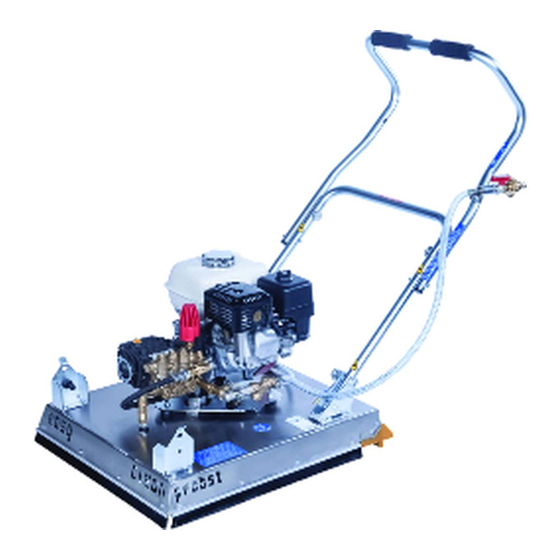
Allgemeines Übersicht und Aufbau Handgriff Wasserzuleitung Benzintank (Einfüllöffnung) Druckeinstellung mit Überdruckventil Hochdruckpumpe Verbrennungsmotor Räder Düse Rotationsarm Technische Daten Die genauen technischen Daten (wie z.B. Tragfähigkeit, Eigengewicht, etc.) sind dem Typenschild zu entnehmen. 51700004 8 / 18... -
Page 14: Installation
Installation Installation Transport Gerät nur an den Handgriffen tragen! ➔ Hierbei ist zu beachten, dass die Federriegel an allen 4 Positionen eingerastet sind und der Bügel sicher in der Transportposition verankert ist. Federriegel Federriegel Aufbau Zum Aufbau des Gerätes die vier Federriegel herausziehen und verdrehen, den Handgriff aufrichten und in der Endposition wieder arretieren (zurückdrehen und einrasten lassen). -
Page 15: Wasseranschluss
Installation Wasseranschluss Wasserschlauch mit dem ¾“-Anschluss am Handgriff des EC-60 verbinden. Es ist darauf zu achten, dass sich der Kugelhahn in geschlossener Stellung befindet. ➔ Ist nur ein ½“-Anschluss (mit Stecksystem) vorhanden, so muss ein Adapterstück verwendet werden. ➔ 51700004 10 / 18... -
Page 16: Bedienung
Bedienung Bedienung Allgemein Die Pumpe darf nicht im Trockenlauf (ohne Wasserzufuhr) betrieben werden! Die Pumpe darf max. 5 Minuten mit Lanze/Strahldüse im Dauerlauf betrieben werden, ohne Wasseraustritt. Um Schäden am Gerät (EC-60) zu vermeiden, darf die Wasserzulauftemperatur 40° C nicht überschreiten. -
Page 17: Arbeiten Mit Lanze/Hochdruck- Und Niederdruckdüse
Bedienung Motor starten Drehzahl- regelung • Starthebel auf ON stellen (Bild 2) • Kraftstoffhahn öffnen (Bild 3) Choke Starthebel • Choke aktivieren (Bild 3) Kraftstoff- hahn Bild 2 Bild 3 Bei Bedarf Querspülung öffnen (auf/open). (Schmutz wird dadurch nach rechts weggespült) Siehe Bild 4 Querspülung Bild 4... -
Page 18: Zumischen Von Reinigungsmitteln
Bedienung 5.2.1 Zumischen von Reinigungsmitteln Soll bei starkem Verschmutzungsgrad der Oberfläche zusätzlich ein Reinigungsmittel zugemischt werden, muss ein Saugschlauch angeschlossen werden (siehe Bild 5, 5b). Beim Zumischen von Reinigungsmitteln muss die Lanze auf Niederdruck umgestellt werden! Pistole mit Lanze (Flachstrahldüse) Wechselsatz Lanze mit Rotationsdüse (Fräskopf) Bild 6... -
Page 19: Wartung Und Pflege
Wartung und Pflege Wartung und Pflege Wartung Um eine einwandfreie Funktion, Betriebssicherheit und Lebensdauer des Gerätes zu gewährleisten, sind die in der unteren Tabelle aufgeführten Wartungsarbeiten nach Ablauf der angegebenen Fristen durchzuführen. Es dürfen nur Original-Ersatzteile verwendet werden, ansonsten erlischt die Gewährleistung. Alle Arbeiten dürfen nur bei stillgelegtem Gerät erfolgen! Bei allen Arbeiten muss sichergestellt sein, dass sich das Gerät nicht unabsichtlich schließen kann. - Page 20 Wartung und Pflege Schmutzfänger (Filtersieb) Zur Gewindeabdichtung: Loctite 542 (flüssig) verwenden Als Montagefett: Lithiumverseiftes, wasserbeständiges Fett verwenden Als Öl (für Kurbelbetrieb): Mineralisches Motorenöl 15W40 verwenden Da bei längeren Stillstandszeiten des Gerätes Kalkablagerungen entstehen, unbedingt mit kalkarmen Wasser die Leitungen durchspülen. Bei Temperaturen um den Gefrierpunkt unbedingt die Pumpe und alle Wasserleitungen komplett entleeren.
-
Page 21: Störungsbeseitigung
Wartung und Pflege Störungsbeseitigung STÖRUNG URSACHE BEHEBUNG • Siehe Bedienungsanleitung des • Fehler am Motor Motors (Anhang) Motor startet nicht. • Beim Startvorgang Pistole an • Sprühlanze erzeugt Gegendruck Sprühlanze betätigen • Wasserzuleitung prüfen • Kein Wasserzufluss • Drehdurchführung prüfen •... -
Page 22: Reparaturen
• Die dementsprechenden gesetzlichen Bestimmungen u. die der Konformitätserklärung sind zu beachten! • Die Durchführung der Sachkundigenprüfung kann auch durch den Hersteller Probst GmbH erfolgen. Kontaktieren Sie uns unter: service@probst-handling.de • Wir empfehlen, nach durchgeführter Prüfung und Mängelbeseitigung des Gerätes die Prüfplakette „Sachkundigenprüfung/ Expert inspection“... -
Page 23: Hinweis Zum Typenschild
(z.B. Kran, Kettenzug, Gabelstapler, Bagger...) mit zu berücksichtigen. Beispiel: Hinweis zur Vermietung/Verleihung von PROBST-Geräten Bei jeder Verleihung/Vermietung von PROBST-Geräten muss unbedingt die dazu gehörige Original- Betriebsanleitung mitgeliefert werden (bei Abweichung der Sprache des jeweiligen Benutzerlandes, ist zusätzlich die jeweilige Übersetzung der Original-Betriebsanleitung mit zuliefern)! Entsorgung / Recycling von Geräten und Maschinen... - Page 24 11/07/04 17:29:49 34Z4M600_001 EINFÜHRUNG Vielen Dank, dass Sie sich für einen Motor von Honda entschieden haben. Wir möchten Ihnen dabei helfen, die besten Ergebnisse mit Ihrem neuen Motor zu erzielen und ihn sicher zu betreiben. Dieses Handbuch enthält BEDIENUNGSANLEITUNG diesbezügliche Informationen; bitte lesen Sie es sorgfältig durch, bevor Sie den Motor in Betrieb nehmen.
-
Page 25: Sicherheitsinformation
11/07/04 17:30:09 34Z4M600_002 SICHERHEITSINFORMATION POSITION VON SICHERHEITSPLAKETTEN Machen Sie sich mit der Funktion aller Bedienungselemente vertraut, Diese Plaketten warnen Sie vor möglichen Gefahren. Sie können ernsthafte und prägen Sie sich ein, wie der Motor im Notfall schnell abzustellen ist. Verletzungen vermeiden helfen. Lesen Sie sie bitte aufmerksam. Stellen Sie sicher, dass die Bedienungsperson vor Benutzung der Wenn sich eine Plakette abgelöst hat oder schwer leserlich geworden ist, Ausrüstung ausreichende Anweisungen erhält. -
Page 26: Ausstattungsmerkmale
11/07/04 17:30:22 34Z4M600_003 LAGE VON TEILEN UND BEDIENUNGSELEMENTEN AUSSTATTUNGSMERKMALE KRAFTSTOFFEINFÜLLVERSCHLUSS OIL ALERT -SYSTEM (Typen mit entsprechender Ausstattung) ‘‘Oil Alert ist eine eingetragene Marke in den USA’’ KRAFTSTOFFTANK Das Oil Alert-System dient zur Verhinderung von Motorschäden, die durch unzureichende Ölmenge im Kurbelgehäuse verursacht werden. Bevor der Ölstand im Kurbelgehäuse unter die Sicherheitsgrenze fallen kann, stoppt das Oil Alert-System den Motor automatisch (der Motorschalter verbleibt in der Position ON). -
Page 27: Kontrollen Vor Dem Betrieb
11/07/04 17:30:46 34Z4M600_004 KONTROLLEN VOR DEM BETRIEB BETRIEB IST DER MOTOR BETRIEBSBEREIT? VORKEHRUNGEN FÜR SICHEREN BETRIEB Um Ihre Sicherheit zu gewährleisten, die Einhaltung von Bitte lesen Sie die Abschnitte SICHERHEITSINFORMATION auf Seite und Umweltvorschriften sicherzustellen und die Lebensdauer der Ausrüstung KONTROLLEN VOR DEM BETRIEB auf Seite , bevor Sie den Motor zum zu maximieren, ist der Zustand des Motors vor jeder Inbetriebnahme zu ersten Mal in Betrieb nehmen. - Page 28 11/07/04 17:31:06 34Z4M600_005 Den Gashebel um etwa 1/3 des Weges von der Position MIN. weg auf Den Starter betätigen. die Position MAX. zu bewegen. STARTZUG: GASHEBEL Den Startgriff leicht ziehen, bis Widerstand zu spüren ist, dann den Griff kräftig in Pfeilrichtung durchziehen, wie unten gezeigt. Den Startgriff sachte zurückführen.
-
Page 29: Stoppen Des Motors
11/07/04 17:31:23 34Z4M600_006 STOPPEN DES MOTORS EINSTELLEN DER MOTORDREHZAHL Zum Stoppen des Motors in einem Notfall schalten Sie einfach den Den Gashebel auf die gewünschte Motordrehzahl einstellen. Motorschalter aus (Stellung OFF). Bei normalen Verhältnissen gehen Sie wie nachfolgend beschrieben vor. Siehe Anweisungen des Für manche Motoranwendungen wird anstelle des hier gezeigten Ausrüstungsherstellers. -
Page 30: Wartung Des Motors
11/07/04 17:31:49 34Z4M600_007 WARTUNG DES MOTORS walten. Zum Reinigen von Teilen nur ein nicht entflammbares Lösungsmittel, kein Benzin verwenden. Zigaretten, Funken und Flammen von allen Kraftstoffteilen fern halten. DIE BEDEUTSAMKEIT RICHTIGER WARTUNG Gute Wartung ist für sicheren, wirtschaftlichen und störungsfreien Betrieb Denken Sie daran, dass ein autorisierter Honda-Wartungshändler Ihren von ausschlaggebender Bedeutung. -
Page 31: Tanken
11/07/04 17:32:07 34Z4M600_008 TANKEN Sorgfältig tanken, um Verschütten von Kraftstoff zu vermeiden. Den Tank nicht ganz auffüllen. Je nach Betriebsbedingungen muss der Empfohlener Kraftstoff Kraftstoffstand eventuell gesenkt werden. Nach dem Tanken den Bleifreies Benzin Tankdeckel wieder andrehen, bis er klickt. ‘‘Pump Octane Number’’... -
Page 32: Ölstandkontrolle
11/07/04 17:32:34 34Z4M600_009 Ölstandkontrolle Den Öleinfüllverschluss/Messstab einsetzen und sicher anziehen. UNTERLEGSCHEIBE Den Motorölstand bei gestopptem und waagerecht stehendem Motor prüfen. ABLASSSCHRAUBE Den Öleinfüllverschluss/Messstab abnehmen und sauber wischen. Den Öleinfüllverschluss/Messstab wie gezeigt in den Öleinfüllstutzen einführen, ohne ihn einzudrehen, und dann zum Prüfen des Ölstands herausnehmen. - Page 33 11/07/04 17:32:58 34Z4M600_010 6 : 1-Untersetzungsgetriebe 6 : 1-Untersetzungsgetriebe ÖLSTAND ÖLEINFÜLLSCHRAUBE Ölstandkontrollschraube mit Scheibe Das Öl bei warmem Motor ablassen. Warmes Öl läuft schnell und abnehmen und prüfen, ob sich der vollständig ab. Ölstand am Rand der Schraubenbohrung befindet. Zum Auffangen des Öls einen geeigneten Behälter unter das Untersetzungsgetriebe setzen, dann Einfüllschraube, Wenn sich der Ölstand unter der Ölstandkontrollschraube und Scheiben abnehmen.
- Page 34 11/07/04 17:33:21 34Z4M600_011 Reinigung STANDARD-DOPPELFILTEREINSATZTYP Schmutz von der Innenseite des Luftfiltergehäuses und -deckels mit einem feuchten Lappen abwischen. Darauf achten, dass kein Schmutz in Typen mit Doppel-Filtereinsatz den zum Vergaser führenden Luftkanal gelangt. FLÜGELMUTTER LUFTFILTERDECKEL Die Flügelmutter vom Den Schaumfiltereinsatz auf den Papiereinsatz setzen, und den Luftfilterdeckel abschrauben, und zusammengesetzten Luftfilter einbauen.
- Page 35 11/07/04 17:33:47 34Z4M600_012 Flachprofiltypen Den Kraftstoffhahn auf ON stellen und auf Undichtigkeit prüfen. Den KLAMMER LUFTFILTERDECKEL O-Ring auswechseln, falls Undichtigkeit vorhanden ist. Die Luftfilterdeckelklipps aufschnappen, den ZÜNDKERZE Luftfilterdeckel abnehmen, und Empfohlene Zündkerzen: BPR6ES (NGK) den Luftfiltereinsatz entnehmen. W20EPR-U (DENSO) Den Luftfiltereinsatz in einer Lösung aus Haushalt- Die empfohlene Zündkerze hat den korrekten Wärmewert für normale Reinigungsmittel und warmem...
- Page 36 11/07/04 17:34:15 34Z4M600_013 NÜTZLICHE TIPPS UND EMPFEHLUNGEN FUNKENSCHUTZ (Typen mit entsprechender Ausstattung) In Europa und anderen Ländern, wo die Maschinenrichtlinie 2006/42/EC LAGERN DES MOTORS anzuwenden ist, empfiehlt es sich, diese Reinigung von Ihrer Kundendienstwerkstatt vornehmen zu lassen. Lagerungsvorbereitung Eine sachgemäße Lagerungsvorbereitung ist ausschlaggebend, um Je nach Motortyp ist ein Funkenschutz serienmäßig eingebaut oder als störungsfreien Betrieb und gutes Aussehen des Motors aufrechtzuerhalten.
- Page 37 11/07/04 17:34:40 34Z4M600_014 Entleeren von Kraftstofftank und Vergaser Lagerungsvorkehrungen Soll der Motor mit Benzin in Kraftstofftank und Vergaser gelagert werden, ist es wichtig, die Gefahr einer Benzindampfentflammung zu verringern. Wählen Sie einen gut belüfteten Lagerraum fern von Geräten, die mit Benzin ist äußerst feuergefährlich und explosiv, und Sie Flammen arbeiten, wie z.B.
- Page 38 11/07/04 17:34:57 34Z4M600_015 BEHEBUNG UNERWARTETER PROBLEME SICHERUNGSAUSTAUSCH (Typen mit entsprechender Ausstattung) Die Starterrelaisschaltung und die Batterie-Ladeschaltung sind durch eine MOTOR SPRINGT Mögliche Ursache Korrektur Sicherung geschützt. Falls die Sicherung durchbrennt, funktioniert der NICHT AN Elektrostart (Typen Batterie entladen. Batterie nachladen. elektrische Starter nicht.
- Page 39 11/07/04 17:35:19 34Z4M600_016 TECHNISCHE INFORMATION Fernsteuergestänge Position der Seriennummer Gas- und Choke-Hebel sind mit Löchern für optionale Seilzugbefestigung Tragen Sie bitte versehen. Die folgenden Abbildungen zeigen Installationsbeispiele für Motorseriennummer, Typ und einen Festdrahtzug und einen flexiblen Flechtdrahtzug. Bei Verwendung Kaufdatum in die Felder unten ein. eines flexiblen Flechtdrahtzugs ist eine Rückholfeder anzubringen, wie Sie benötigen diese Information zur gezeigt.
- Page 40 11/07/04 17:35:37 34Z4M600_017 Vergasermodifikationen für Betrieb in Höhenlagen Informationen zum Schadstoffbegrenzungssystem In Höhenlagen ist das Standard-Kraftstoff-/Luftgemisch des Vergasers zu Emissionsursache fett. Die Leistung nimmt ab, der Kraftstoffverbrauch hingegen zu. Ein sehr Durch den Verbrennungsprozess werden Kohlenmonoxid, Stickstoffoxide fettes Gemisch führt auch zu einer Verschmutzung der Zündkerze und zu und Kohlenwasserstoffe erzeugt.
- Page 41 11/07/04 17:36:02 34Z4M600_018 Abscheidungsgrad Technische Daten (Für Vertrieb in Kalifornien zertifizierte Modelle) GX120 (Zapfwellentyp S, mit Kraftstofftank) × × 329 mm Motoren mit Zertifikation für eine Emissionshaltbarkeitsdauer in Länge × Breite × Höhe 13,0 kg Übereinstimmung mit den California Air Resources Board-Anforderungen Trockengewicht [gewicht] Obengesteuerter Viertakt-Einzylindermotor sind mit einem Abscheidungsgrad-Informationsetikett versehen.
- Page 42 11/07/04 18:10:02 34Z4M600_019 Abstimmspezifikationen GX120/160/200 Schaltschemata GEGENSTAND TECHNISCHE WARTUNG Mit Ölstandswarnung und elektrischem Starter DATENSPECIFICATION Elektrodenabstand 0,7 0,8 mm − Siehe Seite: 12 Leerlaufdrehzahl 1.400 + min (U/min) Siehe Seite: 13 − Ventilspiel GX120 EINLASS: 0,15 ± 0,02 mm Wenden Sie sich bitte (kalt) GX200 AUSLASS: 0,20...
-
Page 43: Verbraucherinformation
11/07/04 17:36:52 34Z4M600_020 《 》 VERBRAUCHERINFORMATION Honda-Geschäftsstelle Wenn Sie schreiben oder anrufen, geben Sie bitte diese Informationen an: Garantie und Vertrieb-/Händlersuchinformation Name des Ausrüstungsherstellers und Modellnummer der Ausrüstung, Vereinigte Staaten, Puerto Rico und Amerikanische Jungferninseln: an der der Motor montiert ist Besuchen Sie unsere Website: www.honda-engines.com Motormodell, Seriennummer und Typ (siehe Seite Name des Händlers, bei dem Sie den Motor gekauft haben... - Page 44 POMPE A PISTONI AD ALTA PRESSIONE HIGH-PRESSURE PISTON PUMPS POMPES A PISTONS A HAUTE PRESSION HOCHDRUCK-KOLBENPUMPE BOMBAS DE PISTÓN DE ALTA PRESIÓN LW - LW-K - FW - ZW - ZW-K - HW - AX - TW MANUALE DI USO E MANUTENZIONE USE AND MAINTENANCE MANUAL (GB) MANUEL D’UTILISATION ET D’ENTRETIEN...
- Page 45 LW - ZW LW-K - ZW-K...
- Page 48 INHALT ERSTER TEIL 1. ALLGEMEINE INFORMATIONEN _______________________________60 1.1 GARANTIEBEDINGUNGEN ..............61 1.2 HERSTELLERANSCHRIFT.................61 1.3 GEBRAUCH UND AUFBEWAHRUNG DER ANWENDUNGS- UND WARTUNGSANLEITUNG .........61 1.4 ZEICHENERKLÄRUNG UND DEFINITIONEN ........62 1.4.1 SYMBOLE ........................62 1.4.2 DEFINITIONEN......................62 2. EIGENSCHAFTEN UND TECHNISCHE DATEN ____________________62 2.1 BESTANDTEILIDENTIFIKATION .............64 2.2.
-
Page 49: Erster Teil
VORWORT Das vorliegende Handbuch besteht aus zwei gesonderten Teilen. Der erste ist sowohl für den Endverbraucher, als auch für den Spezialisierten Techniker bestimmt, der zweite richtet sich ausschließlich an den Spezialisierten Techniker. Unter Spezialisierter Techniker ist zu verstehen: Der Hersteller der Maschine (z.B. der Motorpumpe), in die die Pumpe eingebaut ist (ab hier •... -
Page 50: Herstelleranschrift
(Kassenzettel, Rechnung usw.), unter der Bedingung, dass die der Pumpenunterlagen beiliegende Garantiebescheinigung komplett ausgefüllt innerhalb von 10 Tagen nach dem Kaufdatum an den Hersteller zurückgesandt wird. Der Käufer hat ausschließlich Recht auf den Ersatz der Teile, die nach Urteil des Herstellers oder eines hierzu befugten Vertreters, Material- oder Fabrikationsfehler aufweisen, mit Ausschluss jedes Rechts auf Entschädigung jeglichen direkten oder indirekten Schadens jeglicher Art. -
Page 51: Symbole
und Wartungshandbuch bei. Das vorliegende Handbuch wurde von uns mit Sorgfalt ausgearbeitet. Sollten Sie jedoch auf Fehler stoßen, teilen Sie diese bitte dem Hersteller oder einem befugten Kundendienstzentrum mit. Der Hersteller behält sich zudem das Recht vor, ohne Vorankündigung sämtliche für die Erneuerung und die Korrektur dieser Veröffentlichung erforderlichen Änderungen anzubringen. - Page 52 Die ersten Buchstaben der Pumpenmodellkennzeichnung ermöglichen es, das spezifische Modell zu ermitteln (LW, FW, ZW, HW, TW, SW, AX); der dritte Buchstabe ermöglicht es, die maximale Drehgeschwindigkeit nach der nachfolgenden Tabelle zu ermitteln: Dritter Buchstable D/min 1000 Nicht vorhanden 1450 1750 2800 3400...
-
Page 53: Bestandteilidentifikation
2.1 BESTANDTEILIDENTIFIKATION Halten Sie sich an die Abbildungen 1 und 2 am Anleitungsbeginn. 2.2 SICHERHEITSVORRICHTUNGEN ACHTUNG Die Maschine, in welcher die Pumpe eingebaut wird, muss immer mit einem • Druckbegrenzungs/Druckeinstellventil ausgestattet sein. Sollte , die mit der Pumpe eingebauten Maschine mit einem Sicherheitsventil ausgestattet •... -
Page 54: Betrieb
- Brennstoffe und Schmiermittel jeglicher Art; - Entzündliche Flüssigkeiten oder verflüssigte Gase; - Flüssigkeiten, die als Lebensmittel dienen; - Wasser mit einer Temperatur über 60°C oder unter 5°C; Die Pumpe darf nicht zum Reinigen von: Personen, Tieren, unter Spannung stehenden •... -
Page 55: Hydraulischer Anschluss
Die von der gewöhnlichen Wartung vorgesehenen Kontrollen mit besonderem Bezug auf die • das Öl betreffenden vornehmen. a) Den Öldeckel ohne Entlüftung (17) mit dem Öldeckel mit Entlüftung (8) ersetzen. Diese Operation könnte schon vom Hersteller der Maschine, welche die Pumpe beinhaltet, vorgenommen worden sein. -
Page 56: Standardfunktion (Bei Hochdruck)
Die Pumpe nicht mit Unreinheiten enthaltendem Wasser speisen. Sollte es dazu kommen, • die Pumpe einige Minuten lang mit sauberem Wasser betreiben. 4.2 STANDARDFUNKTION (MIT HOCHDRUCK) ACHTUNG Der Gebrauch der Pumpe erfordert Aufmerksamkeit und Vorsicht. Nicht Anderen die Pumpe •... -
Page 57: Reinigungsmittel-Funktion
Der Arbeitsdruck darf niemals den für die Pumpe vorgesehenen Maximalwert überschreiten • (siehe auch Abschnitt „TECHNISCHE EIGENSCHAFTEN“). Der Anschluss an das Stromnetz der Maschine, in die die Pumpe eingebaut ist, muss • in Übereinstimmung mit den im Land des Gebrauchs geltenden Vorschriften von einem qualifizierten Elektriker vorgenommen werden. -
Page 58: Maschinenhalt
AX. serienmäig vorgesehen. Für die Anwendungsmodalität des Reinigungsmittels, sich auf die Etikettenanweisungen an der Reinigungsmittelverpackung halten und die Dosierung besonders beachten. Um nachfolgendes korrekt durchzuführen, auch die Anwendungs- und Wartungsanleitung der Maschine, welche die eingebaute Pumpe beinhaltet, beachten. a) Den Pumpendruck unter 30 Bar/435 psi verringern (z.B. bei einer Wasserreinigungsmaschine wird dies erzielt, wenn die Niederdruckfunktion auf einem mit entsprechendem Düsenkopf ausgestatteten Wasserwerfer, eingeschaltet wird). -
Page 59: Gewöhnliche Wartung
WARNUNG Nach Anwendung, immer die Flüssigkeit komplett aus der Pumpe leeren und die Gebrauchs- • und Wartungsanleitungen der Maschine (in der die Pumpe eingebaut ist) beachten. Die Pumpe ist frostempfindlich. Befindet sich die Maschinen in kalten Räumen kann, um die Eisbildung im Pumpeninneren zu vermeiden, vor Operationsbeginn „MASCHINENHALT“... -
Page 60: Aussergewöhnliche Wartung
6.3 AUSSERGEWÖHNLICHE WARTUNG ACHTUNG Die außergewöhnlichen Wartungsvorgänge sind ausschließlich von einem Spezialisierten • Techniker vorzunehmen. Um die Sicherheit der Pumpe zu gewähren, dürfen nur die vom Hersteller gelieferten oder • von ihm genehmigten Originalersatzteile benützt werden. Das Altöl muss angemessen entsorgt und nicht in der Umwelt verbreitet werden. •... -
Page 61: Zweiter Teil
URSACHEN BETRIEBSSTÖRUNGEN ABHILFE Die Pumpe füllt nicht an. Luftansaugung Die Integrität des Ansaugkreislaufs überprüfen. Der Auslass ist geschlossen(z.B. bei einer Den Förderdruck nullstellen (z.B. bei einer Wasserreinigungsmaschine befindet sich die Wasserreinigungsmaschine muss der Wasserpistole in geschlossener Position) Wasserpistolenhebel gedrückt werden) Die Pumpe erreicht den Höchstdruck Das Druckbegrenzungs/Druckeinstellventil ist Den korrekten Druckwert einstellen(bei den... -
Page 62: Standardausstattung
Hat man die Pumpe ausgepackt, ist sich über deren Unversehrtheit zu vergewissern und • darauf zu achten, dass das Identifikationsschild vorhanden und lesbar ist. Im Zweifelsfall darf die Pumpe keineswegs verwendet werden und es ist sich an den Händler zu wenden. 1.1 STANDARDAUSSTATTUNG Vergewissern Sie sich darüber, dass folgende Teile stets die Pumpe begleiten: Öldeckel mit Entlüftung (8);... -
Page 63: Applikationen
Ansaugfitting verschiedener Formen und Abmessungen; • Manometer; • u.s.w. • Für weitere Informationen wenden Sie sich bitte an Ihren Detailhändler. 2.2 APPLIKATIONEN ACHTUNG • Die beweglichen Maschinenteile mit zweckmäßigen Protektionen schützen. Besondere Vorsicht ist den Riemenscheiben-Applikationen vorbehalten. • Die Pumpe darf nicht mit einer Drehgeschwindigkeit über der am Datenschild entnehmbaren, arbeiten (siehe auch Abschnitt „EIGENSCHAFTEN UND TECHNISCHE DATEN“. -
Page 64: Wasseranschluss
Nachfolgend eine Tabelle mit der Zusammenfassung der in diesen Anleitungen beschriebenen zahlreichen Pumpenapplikationen. Wenden Sie sich immer an den Detailhändler oder Hersteller, um die korrekte Applikation zu ermitteln. Unter Beachtung der Mechanikregeln, die Anbringung dieser an der Pumpe durchführen. Der Technische Servicedienst des Herstellers steht dem Installateur für die notwendigen Informationen zur Verfügung. -
Page 65: Aussergewöhnliche Wartung
1000 1300 1500 1600 1700 1900 2000 2200 2300 2500 2600 3000 3600 4000 11,3 13,2 15,2 17,5 18,0 21,0 22,4 3. AUSSERGEWÖHNLICHE WARTUNG Halten Sie sich an den Inhalt des Abschnittes 6.3., erster Teil. Die anzuwendenden Anzugsmomente sind in der nachfolgenden Tabelle angeführt (sich an die Abb.4 halten). -
Page 66: Fabrikantenerklärung
FABRIKANTENERKLÄRUNG Gemäss EG-Richtlinie 98/37 Comet S.p.A. Via G. Dorso, 4 - 42100 Reggio Emilia - Italien Erklärt unter eigener Verantwortung, dass die Pumpe der Serie: LW LW-K FW ZW ZW-K Mit Seriennummer (vom Käufer anzugeben, aus dem Schild mit den technischen Daten erkenntlich): ________________________________________________________ auf die diese Erklärung sich bezieht, mit den Anforderungen der EG-Richtlinie 98/37 übereinstimmt. - Page 67 LWD-K VERSION - 3400 RPM POS. CODICE DESCRIZIONE Q.tà MODELLI POS. CODICE DESCRIZIONE Q.tà MODELLI ITEM PART No. DESCRIPTION Qty. MODELS ITEM PART No. DESCRIPTION Qty. MODELS 3218.0112.00 MANIFOLD Ø 15 mm 3011.0014.00 WRIST. PIN 3202.0018.00 CAP G1/8 0205.0048.00 CON. ROD 2010 E - 2010 G 2015 E - 2015 G 3609.0108.00...
- Page 68 LWD-K VERSION - 3400 RPM E version POS. CODICE DESCRIZIONE Q.tà MODELLI ITEM PART No. DESCRIPTION Qty. MODELS POS. CODICE DESCRIZIONE Q.tà MODELLI 0009.0206.00 E-F BACK-UP RING ITEM PART No. DESCRIPTION Qty. MODELS 0009.0207.00 SEAT 3609.0032.00 SCREW M6X20 1802.0181.00 SPRING 2010 E - 2010 G 3016.0016.00 FLANGE...
- Page 69 (durch eine autorisierte Fachwerkstatt)! Nach jeder erfolgten Durchführung eines Wartungsintervalls muss unverzüglich dieser Wartungsnachweis (mit Unterschrift u. Stempel) an uns übermittelt werden. per E-Mail an: service@probst-handling.de / per Fax oder Post Betreiber: _ _ _ _ _ _ _ _ _ _ _ _ _ Gerätetyp:...
- Page 73 Operating Instructions Translation of original operating instructions EASYCLEAN EC-60 Paver Cleaning Device EC-60 51700004...
- Page 74 Bitte beachten Sie, dass das Produkt ohne vorliegende Betriebsanleitung in Landessprache nicht eingesetzt / in Betrieb gesetzt werden darf. Sollten Sie mit der Lieferung des Produkts keine Betriebsanleitung in Ihrer Landessprache erhalten haben, kontaktieren Sie uns bitte. In Länder der EU / EFTA senden wir Ihnen diese kostenlos nach. Für Länder außerhalb der EU / EFTA erstellen wir Ihnen gerne ein Angebot für eine Betriebsanleitung in Landessprache, falls die Übersetzung nicht durch den Händler/Importeur organisiert werden kann.
- Page 75 Safety procedures .......................... 17 Hints to the type plate ........................18 Hints to the renting/leasing of PROBST devices ................18 Disposal / recycling of devices and machines .................. 18 We hereby reserve the right to make changes to the information and illustrations in the operating instructions.
-
Page 76: Ec-Declaration Of Conformity / Ukca-Declaration Of Conformity
Address: Probst GmbH; Gottlieb-Daimler-Straße 6; 71729 Erdmannhausen, Germany Authorized person for UK-documentation: Name: Nigel Hughes Address: Probst Ltd ; Unit 2 Fletcher House; Stafford Park 17; Telford Shropshire TF3 3DG, United Kingdom Signature, information to the subscriber: Erdmannhausen, 08.02.2023................(Eric Wilhelm, Managing director) -
Page 77: Safety
Safety Safety Safety symbols Danger to life! Identifies imminent hazard. If you do not avoid the hazard, death or severe injury will result. Hazardous situation! Identifies a potentially hazardous situation. If you do not avoid the situation, injury or damage to property can result. -
Page 78: Definition Skilled Worker / Specialist
Safety Open/close cross-flushing. 29040300 20x86 mm Minimum water pressure 0.3 bar 29040395 180x20 At temperatures around freezing point, it is essential to drain the pump and all water lines completely. 29040565 125x75 mm For all maintenance work requiring the unit to be tilted, the angle of inclination must not exceed >30°! Definition skilled worker / specialist Only skilled workers or specialists are allowed to carry out the installation-, maintenance-, and repair work on this... -
Page 79: Safety Procedures
Safety Safety procedures • The device may not be operated in closed areas (danger of poisoning by exhaust gases). • Refuelling the device may take place only, if the engine is so far cooled down that no fire and danger of explosion exist. -
Page 80: General
General General Authorized use The device is intended exclusively for cleaning flat slabs and paved surfaces. The device is not self- priming, i.e. the device must be supplied with clean, bubble-free tap water. Make sure that the cleaning area is sealed by the protective hood and the brushes attached to it. The surface to be cleaned must be able to withstand the pressurization by the water jet without damage. -
Page 81: Survey And Construction
General Survey and construction Handle Water supply line Gasoline tank (filler opening) Pressure adjustment with relief valve High pressure pump Internal combustion engine Wheels Nozzle Rotationsarm Technical data The exact technical data (carrying capacity / working load limit (WLL), dead weight, etc.) are listed on the type plate. 51700004 8 / 18... -
Page 82: Installation
Installation Installation Transport Carry the device by the handles only! ➔ Make sure that the spring latches are engaged in all 4 positions and that the stirrup is securely anchored in the transport position. Spring bolt Spring bolt Structure To assemble the unit, pull out and twist the four spring latches, straighten the handle and lock it again in the end position (turn back and let it click into place). -
Page 83: Water Connection
Installation Water connection Connect the water hose to the ¾" connection on the handle of the EC 60.*. It must be ensured that the ball valve is in the closed position. ➔ If only a ½" connection (with plug-in system) is available, an adapter piece must be used. -
Page 84: Operation
Operation Operation General The pump must not be operated in dry running mode (without water supply)! The pump may be operated for max. 5 minutes with lance/jet nozzle in continuous operation, without water discharge. In order to avoid damage to the unit (EC-60), the water feed temperature must not exceed 40° The feed water from the piping system must be filtered with 300-400 µ. -
Page 85: Working With Lance/High-Pressure And Low-Pressure Nozzle
Operation Start engine Speed control • Set start lever to ON (Fig. 2) • Open fuel cock (picture 3) Choke Start lever • - Activate choke (picture 3) Fuel tap Fig 2 Fig 3 If necessary, open cross-flushing (open/open). (Dirt is thereby flushed away to the right) Fig. 4 Cross-flushing Fig 4 The speed of rotation of the motor and the feed rate of the (EC-60) must be adjusted and optimized depending... -
Page 86: Adding Cleaning Agents
Operation 5.2.1 Adding cleaning agents If an additional cleaning agent is to be added if the surface is heavily soiled, a suction hose must be connected (see Fig. 5, 5b). When mixing cleaning agents, the lance must be switched to low pressure! Gun with lance (flat spray nozzle) Exchange set lance with rotary nozzle (cutter head) -
Page 87: Maintenance And Care
Maintenance and care Maintenance and care Maintenance To ensure the correct function, safety and service life of the device the following points must be executed in the maintenance interval. Used only original spare parts, otherwise the warranty expires. All operations may only be made in closed state of the device! For all operations you have to make sure, that the device will not close unintended. - Page 88 Maintenance and care Clean dirt filter 1x per month (rinse with water jet, tap out if necessary). Dirt trap (Filter sieve) For thread sealing: Use Loctite 542 (liquid) As assembly grease: Use lithium saponified, water-resistant grease As oil (for crank operation): Use mineral engine oil 15W40 Since limescale deposits are formed when the unit is not used for longer periods of time, it is essential to flush the lines with low-lime water.
-
Page 89: Trouble Shooting
Maintenance and care Trouble shooting ERROR CAUSE REPAIR Engine does not start. • • Error at the engine See operating instructions of the engine (Appendix) • • Spray gun produces back When starting press pistol on pressure spray gun Engine runs but no pressure is •... -
Page 90: Repairs
The corresponding legal regulations and the regulations of the declaration of conformity must be observed! • The expert inspection can also be done by the manufacturer Probst GmbH. Contact us at: service@probst-handling.de We recommend affixing the inspection sticker "„Sachkundigenprüfung / Expert inspection" in a •... -
Page 91: Hints To The Type Plate
Example: Hints to the renting/leasing of PROBST devices With every renting/leasing of PROBST devices the original operating instructions must be included unconditionally (in deviation of the user´s country's language, the respective translations of the original operating instructions must be delivered additionally)! - Page 92 11/07/04 17:14:33 32Z4M600_001 INTRODUCTION Thank you for purchasing a Honda engine. We want to help you to get the best results from your new engine and to operate it safely. OWNER’S MANUAL This manual contains information on how to do that; please read it carefully before operating the engine.
-
Page 93: Safety Information
11/07/04 17:14:52 32Z4M600_002 SAFETY INFORMATION SAFETY LABEL LOCATIONS Understand the operation of all controls and learn how to stop These labels warn you of potential hazards that can cause serious the engine quickly in case of emergency. Make sure the operator injury. -
Page 94: Locations
11/07/04 17:15:04 32Z4M600_003 COMPONENT & CONTROL LOCATIONS FEATURES FUEL FILLER CAP OIL ALERT SYSTEM (applicable types) ‘‘Oil Alert is a registered trademark in the United States’’ FUEL TANK The Oil Alert system is designed to prevent engine damage caused by an insufficient amount of oil in the crankcase. Before the oil level in the crankcase can fall below a safe limit, the Oil Alert system will automatically stop the engine (the engine switch will remain in the ON position). -
Page 95: Checks
11/07/04 17:15:28 32Z4M600_004 BEFORE OPERATION CHECKS OPERATION IS YOUR ENGINE READY TO GO? SAFE OPERATING PRECAUTIONS For your safety, to ensure compliance with environmental Before operating the engine for the first time, please review the regulations, and to maximize the service life of your equipment, it SAFETY INFORMATION section on page and the BEFORE is very important to take a few moments before you operate the OPERATION CHECKS on page . - Page 96 11/07/04 17:15:48 32Z4M600_005 Move the throttle lever away from the MIN. position, about 1/3 Operate the starter. of the way toward the MAX. position. RECOIL STARTER: THROTTLE LEVER Pull the starter grip lightly until you feel resistance, then pull briskly in the direction of the arrow as shown below. Return the starter grip gently.
-
Page 97: Stopping The Engine
11/07/04 17:16:06 32Z4M600_006 STOPPING THE ENGINE SETTING ENGINE SPEED To stop the engine in an emergency, simply turn the engine switch Position the throttle lever for the desired engine speed. to the OFF position. Under normal conditions, use the following procedure. -
Page 98: Servicing Your Engine
11/07/04 17:16:31 32Z4M600_007 SERVICING YOUR ENGINE MAINTENANCE SCHEDULE THE IMPORTANCE OF MAINTENANCE REGULAR SERVICE PERIOD (3) Each First Every 3 Every 6 Every Refer Good maintenance is essential for safe, economical, and trouble- Perform at every Month Months Months Year free operation. - Page 99 11/07/04 17:16:49 32Z4M600_008 REFUELING Refuel carefully to avoid spilling fuel. Do not fill the fuel tank completely. It may be necessary to lower the fuel level depending Recommended Fuel on operating conditions. After refueling, screw the fuel filler cap Unleaded gasoline back on until it clicks.
- Page 100 11/07/04 17:17:15 32Z4M600_009 Oil Level Check Install the oil filler cap/dipstick and tighten securely. Check the engine oil level with the engine stopped and in a level WASHER position. DRAIN PLUG Remove the oil filler cap/dipstick and wipe it clean. Insert the oil filler cap/dipstick into the oil filler neck as shown, OIL FILLER CAP/ DIPSTICK...
- Page 101 11/07/04 17:17:40 32Z4M600_010 6 : 1 Reduction Case 6 : 1 Reduction Case OIL LEVEL FILLER BOLT Remove the oil-level-check bolt Drain the used oil while the engine is warm. Warm oil drains and washer, and see whether the quickly and completely. oil level is at the edge of the bolt hole.
- Page 102 11/07/04 17:18:02 32Z4M600_011 Cleaning Wipe dirt from the inside of the air cleaner case and cover using STANDARD DUAL-FILTER- ELEMENT TYPE a moist rag. Be careful to prevent dirt from entering the air duct Dual-Filter Element Types that leads to the carburetor. WING NUT Place the foam air filter element over the paper element, and Remove the wing nut from...
- Page 103 11/07/04 17:18:29 32Z4M600_012 Low Profile Types Move the fuel valve to the ON position, and check for leaks. CLIP AIR CLEANER COVER Replace the O-ring if there is any leakage. Unsnap the air cleaner cover clips, remove the air cleaner SPARK PLUG cover, and remove the air filter element.
- Page 104 11/07/04 17:18:57 32Z4M600_013 HELPFUL TIPS & SUGGESTIONS SPARK ARRESTER (applicable types) In Europe and other countries where the machinery directive STORING YOUR ENGINE 2006/42/EC is enforced, this cleaning should be done by your servicing dealer. Storage Preparation Proper storage preparation is essential for keeping your engine The spark arrester may be standard or an optional part, depending trouble-free and looking good.
- Page 105 11/07/04 17:19:22 32Z4M600_014 Draining the Fuel Tank and Carburetor Storage Precautions If your engine will be stored with gasoline in the fuel tank and carburetor, it is important to reduce the hazard of gasoline vapor ignition. Select a well ventilated storage area away from any Gasoline is highly flammable and explosive, and you appliance that operates with a flame, such as a furnace, water can be burned or seriously injured when handling...
- Page 106 11/07/04 17:19:39 32Z4M600_015 TAKING CARE OF UNEXPECTED PROBLEMS FUSE REPLACEMENT (applicable types) ENGINE WILL Possible Cause Correction The electric starter relay circuit and battery charging circuit are NOT START protected by a fuse. If the fuse burns out, the electric starter will Battery Recharge battery.
- Page 107 11/07/04 17:20:01 32Z4M600_016 TECHNICAL INFORMATION Remote Control Linkage Serial Number Location The throttle and choke control levers are provided with holes for Record the engine serial optional cable attachment. The following illustrations show number, type and purchase installation examples for a solid wire cable and for a flexible, date in the spaces below.
- Page 108 11/07/04 17:20:18 32Z4M600_017 Carburetor Modifications for High Altitude Operation Emission Control System Information At high altitude, the standard carburetor air-fuel mixture will be Source of Emissions too rich. Performance will decrease, and fuel consumption will The combustion process produces carbon monoxide, oxides of increase.
- Page 109 11/07/04 17:20:43 32Z4M600_018 Air Index Specifications (Models certified for sale in California) GX120 (PTO shaft type S, with fuel tank) × × × × An Air Index Information label is applied to engines certified to an Length Width 329 mm ×...
- Page 110 11/07/04 17:21:04 32Z4M600_019 Tuneup Specifications GX120/160/200 Wiring Diagrams ITEM SPECIFICATION MAINTENANCE − With Oil Alert and Electric Starter Spark plug gap 0.7 0.8 mm Refer to page: 12 − (0.028 0.031 in) + Idle speed 1,400 Refer to page: 13 −...
- Page 111 11/07/04 17:21:32 32Z4M600_020 《 》 CONSUMER INFORMATION Honda’s Office When you write or call, please provide this information: Warranty and Distributor/Dealer Locator Information Equipment manufacturer’s name and model number that the United States, Puerto Rico, and U.S. Virgin Islands: engine is mounted on Visit our website: www.honda-engines.com Engine model, serial number, and type (see page Name of dealer who sold the engine to you...
- Page 112 POMPE A PISTONI AD ALTA PRESSIONE HIGH-PRESSURE PISTON PUMPS POMPES A PISTONS A HAUTE PRESSION HOCHDRUCK-KOLBENPUMPE BOMBAS DE PISTÓN DE ALTA PRESIÓN LW - LW-K - FW - ZW - ZW-K - HW - AX - TW MANUALE DI USO E MANUTENZIONE USE AND MAINTENANCE MANUAL (GB) MANUEL D’UTILISATION ET D’ENTRETIEN...
- Page 113 LW - ZW LW-K - ZW-K...
- Page 116 INDEX FIRST PART 1. GENERAL INFORMATION ______________________________________24 1.1 G ...................24 uarantee conditions 1.2 a ................25 ddress producer 1.3 u ......25 preservation this maintenance manual 1.4 s .................25 ymbol definitions 1.4.1 Simbols ......................25 1.4.2 Definitions ......................26 2. FEATuRES AND TEchNIcAL DATA _____________________________26 2.1 ................27 identification...
- Page 117 FOREWORD This manual is made up of two separate parts. The first one is directed to final user and Skilled Engineer, while the second is only for the Skilled Engineer. By Skilled Engineer we mean: • The producer of the machine (for instance of the motor pump) with built-in pump (from now on, by “machine with built-in pump”...
- Page 118 The product sent to the Producer for repairs in guarantee must be sent complete with any original and not tampered component, otherwise any guarantee request will be refused. The replaced parts become a property of the Producer. Possible failures or breaks that should take place during and after the guarantee period do not give right to the payment suspension not to further delays.
- Page 119 The symbol: WARNING that highlights some parts of the text indicates the possibility to damage the pump if the relevant instructions are not followed. The symbols: 1.4.2 Definitions • By-pass: identifies that particular pump operation that takes place when, during the normal use, you must interrupt the flow rate (for instance, in case of a water cleaner when you release the lever of the water gun).
- Page 120 For instance: TWN 5636 (1000 RPM), LW 2020 (1450 RPM), HWD 4040 (3400 RPM). The presence of letter K, preceded by a hyphen, means that the pump (LW-K, ZW-K) is equipped with an already built-in pressure limiting/adjusting valve (for instance: LWR-K 2020, ZW-K 4022): This rule cannot be applied to the AX models, because they are all already equipped with a built-in pressure limiting/adjusting valve.
- Page 121 Pressure limiting/adjusting valve Mounted as standard on LW-K, ZW-K, AX and available as optional accessory for the other models. It is a valve that makes it possible to adjust the working pressure and that allows the pump fluid to reflow towards the by-pass duct, thus avoiding the onset of dangerous pressures, when you interrupt the flow rate or when you try to set pressure values above the maximum allowed ones.
- Page 122 guaranteed by the presence of the CE marking and by the Declaration of Conformity of the producer of the machine with the built-in pump. • Before commissioning the machine, carefully read the indications of this manual and the instructions of the machine with the built-in pump. In particular, make sure that you have well understood the operation of the pump and of the machine with the built-in pump as far as the fluid sensing operations are concerned.
- Page 123 WARNING • The pressure of the supplied water must not be higher than 8 bar/116 psi. • Do not operate the pump with priming depth higher than 1 m/3.3 ft (AX and pumps at 1000, 1450 and 1750 RPM) or higher than 0.5 m/1.7 ft (pumps at 2800 and 3400 RPM). •...
- Page 124 • Do not remove the protections of the moving parts. • Do not operate on pipes containing fluids under pressure. • Do not carry out maintenance on the pump if it is working. • Observe the instruction of chapter “INTENDED USE”. • Do not change in any way the pump installation conditions and in particular do not change its fixing and hydraulic connections. • Do not deactivate or tamper with the controls, the safety devices and the pressure limiting/ adjusting valve. • The working pressure must never overcome the maximum value that is intended for the pump (see also the paragraph “TECHNICAL FEATURES”. • The connection to the mains of the machine with the built-in pump must be carried out by a Skilled Engineer according to the standard which are valid in the relevant country. To carry out correctly what described below, refer also to the use and maintenance manual of the machine with the built-in pump. Set the delivery pressure to zero, by keeping the delivery circuit opened. In case of a water cleaner, for instance, you just need to press the lever of the water gun.
- Page 125 In case of ingestion, do not induce vomiting and immediately apply to a doctor by bringing with you the detergent package. The possibility to suck detergent is intended as standard only for the models LW-K, ZW-K and For the detergent use modes, refer to the instructions on the label on the detergent package by observing the doses. To carry out correctly what described below, refer also to the use and maintenance manual of the machine with the built-in pump.
- Page 126 cAuTION • By referring to the use and maintenance manual of the machine with the built-in pump, after the use, always empty completely the fluid pump. • The pump is sensitive to frost. In case of very low temperatures, in order to avoid the formation of ice inside the pump, it is possible to activate, before activating the «S »...
- Page 127 EXTRAORDINARY MAINTENANcE cAuTION • The extraordinary maintenance interventions must be carried out only by a Skilled Engineer. • To guarantee the pump safety, only use original spare parts supplied by the Producer or approved by this latter. • The used oil must be duly disposed of and not dispersed in the environment. For the extraordinary maintenance, observe what is reported in the following table. WARNING •...
- Page 128 PROBLEMS CAUSES SOLUTIONS The pump does not prime Air suction Chek the integrity of the suction circuit Delivery side closed (for istance, in case of Set the delivery pression to zero (for istance, water cleaner, water gun in closed position) in case of a water cleaner, press the lever of the water gun) The pump does not reach the maximum...
- Page 129 • After having unpacked the pump, it is necessary to make sure that the device is integer by paying attention that the identification plate is present and readable. In case of doubts, do not absolutely use the pump, but apply to the dealer. 1.1 STANDARD EQuIPMENT Make sure that the package of the purchased product contains the following elements: • oil plug with vent (8); • use and maintenance manual; • guarantee certificate. In case of problems, apply to the dealer or an authorised service centre. ...
- Page 130 2.2 APPLIcATIONS cAuTION • Protect the moving parts with suitable guards. Pay special attention to the pulley applications. • The pump must not work at a rotation speed that is higher than the one indicated on the relevant plate (see also what described in paragraph “F ”. eatures and technical data • The pump must be fixed firmly to the motor flange or on a stable base by means of the (optional) feet. Male Female Female Female Female Female Female Female Female Female Hydraulic shaft shaft...
- Page 131 hYDRAuLIc cONNEcTION Follow the connection prescriptions already explained in paragraph 4.1.1 in the first part. In particular, the sizes of the suction circuit must be suitable not to determine on the suction pump connector: • a pressure value higher than 8 bar /116 psi; •...
- Page 132 3. EXTRAORDINARY MAINTENANcE Observe what described in paragraph 6.3 of the first part. The torque wrench settings to be used are indicated in the following table (refer to fig. 4). Torque wrench setting Nm (lb.ft) LW-Z Fluid to be applied Description on the thread ZW-K...
- Page 133 DEcLARATION OF ThE PRODucER according to Directive: 98/37/EEC. Comet S.p.A. Via G. Dorso, 4 - 42100 Reggio Emilia - Italia declares under its own responsibility that the pump of the series: LW-K ZW-K with serial number (to be reported by the purchaser by referring to the identification plate): ________________________________________________________ to which this declaration refers, conforms with the requirements of Directive 798/37/EEC.
- Page 134 LWD-K VERSION - 3400 RPM POS. CODICE DESCRIZIONE Q.tà MODELLI POS. CODICE DESCRIZIONE Q.tà MODELLI ITEM PART No. DESCRIPTION Qty. MODELS ITEM PART No. DESCRIPTION Qty. MODELS 3218.0112.00 MANIFOLD Ø 15 mm 3011.0014.00 WRIST. PIN 3202.0018.00 CAP G1/8 0205.0048.00 CON. ROD 2010 E - 2010 G 2015 E - 2015 G 3609.0108.00...
- Page 135 LWD-K VERSION - 3400 RPM E version POS. CODICE DESCRIZIONE Q.tà MODELLI ITEM PART No. DESCRIPTION Qty. MODELS POS. CODICE DESCRIZIONE Q.tà MODELLI 0009.0206.00 E-F BACK-UP RING ITEM PART No. DESCRIPTION Qty. MODELS 0009.0207.00 SEAT 3609.0032.00 SCREW M6X20 1802.0181.00 SPRING 2010 E - 2010 G 3016.0016.00 FLANGE...
- Page 136 After each completed performance of a maintenance interval the included form must be fill out, stamped, signed and send back to us immediately. via e-mail to service@probst-handling.de / via fax or post Operator: _ _ _ _ _ _ _ _ _ _ _ _ _...
- Page 137 Instructions d'emploi Traduction des instructions d'emploi originales EASYCLEAN EC-60 Nettoyeur haute pression avec protection contre les projections EC-60 51700004...
- Page 138 Devoir de contrôle .......................... 17 Informations concernant la plaque signalétique ................18 Remarque concernant la location/le prêt des engins PROBST ............. 18 Elimination / recyclage des appareils et des machines ..............18 Nous nous réservons le droit de modifier les informations et les illustrations du mode d'emploi.
-
Page 139: Ce-Déclaration De Conformité
CE-Déclaration de Conformité CE-Déclaration de Conformité Description: EASYCLEAN EC-60 Nettoyeur haute pression avec protection contre les Type: projections N° de commande: EC-60 51700004 Fabricant: Probst GmbH Gottlieb-Daimler-Straße 6 71729 Erdmannhausen, Germany info@probst-handling.de www.probst-handling.com La machine décrite ci-dessus est conforme aux exigences applicables des directives UE suivantes : Idée directrice EC 2006/42/CE... -
Page 140: Sécurité
Sécurité Sécurité Instructions de sécurité Danger de mort ! Désigne un danger. Provoque des blessures graves ou la mort s’il n’est pas évité. Situation dangereuse ! Désigne une situation dangereuse. Risque de blessures légères ou mineures, ou de dommages matériels si elle n’est pas évitée. Interdiction ! Désigne une interdiction. -
Page 141: Définition Personnel Spécialisé / Expert
Sécurité Ouvrir/fermer la chasse d'eau transversale. 29040300 20x86 mm Pression minimale de l'eau 0,3 bar 29040395 180x20 Lorsque les températures avoisinent le point de congélation, il est impératif de vider complètement la pompe et toutes les conduites d'eau. 29040565 125x75 mm Pour tous les travaux de maintenance nécessitant une inclinaison de l'appareil, l'angle d'inclinaison ne doit pas dépasser >30°! -
Page 142: Sécurité En Cours De Fonctionnement
Sécurité Sécurité en cours de fonctionnement • L'appareil ne doit pas être utilisé dans des locaux fermés (risque d'intoxication due aux gaz d'échappement). • Avant de verser du carburant dans l'appareil, le moteur doit être suffisamment refroidi afin d'éviter les risques d'incendie et d'explosion. -
Page 143: Généralités
Généralités Généralités Utilisation conforme L'appareil sert exclusivement au nettoyage de dalles et de surfaces pavées planes. L'appareil n'est pas auto-amorçant, c'est-à-dire que l'appareil doit être alimenté en eau du robinet propre et sans bulles. Il faut veiller à ce que la zone de nettoyage soit rendue étanche par le capot de protection et les brosses qui y sont fixées. -
Page 144: Vue D´ensemble Et Structure
Généralités Vue d´ensemble et structure Poignée Conduite d'eau Réservoir d'essence (ouverture de remplissage) Réglage de la pression avec soupape de surpression Pompe haute pression Moteur à combustion Roues Buse Bras de rotation Caractéristiques techniques Les caractéristiques techniques détaillées (par ex. charge maximale, poids propre, etc.) figurent dans la plaque signalétique. -
Page 145: Installation
Installation Installation Transport Ne porter l'appareil que par les poignées! ➔ Il faut alors veiller à ce que les verrous à ressort soient enclenchés dans les 4 positions et que l'arceau soit bien ancré dans la position de transport. Verrou à ressort Verrou à... -
Page 146: Raccordement À L'eau
Installation Raccordement à l'eau Raccorder le tuyau d'eau au -raccord ¾" -sur la poignée de l'-EC60 Il faut veiller à ce que le robinet à boisseau sphérique soit en position fermée. ➔ S'il -n'y a qu'un seul -raccord ½" -(avec système de connexion), il faut utiliser une pièce d'adaptation. -
Page 147: Maniement
Maniement Maniement Généralités La pompe ne doit pas fonctionner à sec (sans alimentation en eau) ! La pompe peut fonctionner en continu pendant 5 minutes maximum avec lance/buse de projection, sans fuite d'eau. Pour éviter d'endommager l'appareil (EC-60), la température d'arrivée d'eau ne doit pas dépasser 40°... -
Page 148: Travailler Avec Une Lance/Buse Haute Pression Et Basse Pression
Maniement Démarrer le moteur Régulation de la vitesse • Mettre le levier de démarrage sur ON (image 2) Levier de démarrage • Ouvrir le robinet de carburant (image 3) Choke • Activer le starter (image 3) Robinet de carburant Image 2 Image 3 Si nécessaire, ouvrir le rinçage transversal (ouvrir/open). -
Page 149: Ajouter Des Produits De Nettoyage
Maniement 5.2.1 Ajouter des produits de nettoyage Si, en cas de fort encrassement de la surface, un produit de nettoyage doit également être mélangé, un tuyau d'aspiration doit être raccordé (voir figure 5, 5b). Lors du mélange de produits de nettoyage, la lance doit être commutée sur basse pression ! Pistolet avec lance (buse à... -
Page 150: Maintenance Et Entretien
Maintenance et entretien Maintenance et entretien Maintenance Pour que l´appareil fonctionne parfaitement, pour assurer sa sécurité de fonctionnement et une longue durée de vie, il est impératif d’effectuer les opérations de maintenance spécifiées dans le tableau ci- dessous aux intervalles prescrits. Utiliser exclusivement des pièces de rechange d’origine ;... - Page 151 Maintenance et entretien Filtre à tamis (tamis filtrant) Pour l'étanchéité des filetages : Utiliser du Loctite 542 (liquide) Comme graisse de montage : utiliser une graisse saponifiée au lithium et résistante à l'eau Comme huile (pour le fonctionnement à la manivelle) : Utiliser une huile moteur minérale 15W40 Comme des dépôts de calcaire se forment en cas d'arrêt prolongé...
-
Page 152: Élimination Des Dérangements
Maintenance et entretien Élimination des dérangements DERANGEMENT CAUSE SOLUTION Le moteur ne démarre pas. • • défaut au niveau du moteur voir notice d'instructions du moteur (annexe) • • la lance génère une contre- au démarrage, actionner le pistolet de la pression lance Le moteur fonctionne, mais ne... -
Page 153: Réparations
Observer les prescriptions correspondantes des associations professionnelles déclaration de conformité. • Le contrôle expert peut également être effectué par le fabricant Probst GmbH. Contactez-nous à : service@probst-handling.de Lorsqu’un contrôle a été effectué et que les déficiences ont été réparées sur l´appareil, nous •... -
Page 154: Informations Concernant La Plaque Signalétique
Exemple: Remarque concernant la location/le prêt des engins PROBST Lors de chaque location/prêt d’un engin PROBST, les instructions d’emploi originales correspondantes doivent impérativement être jointes (si la langue n’est pas celle de l’utilisateur, une traduction des instructions d’emploi originales dans la langue adéquate doit être fournie) ! Elimination / recyclage des appareils et des machines Le produit ne doit être mis hors service et préparé... - Page 155 11/07/04 17:22:04 33Z4M600_001 INTRODUCTION Nous vous remercions d’avoir porté votre choix sur un moteur Honda. Nous désirons vous aider à faire le meilleur usage de votre nouveau moteur et à l’utiliser en sécurité. Vous trouverez dans ce manuel des informations sur la manière d’y parvenir; veuillez le lire attentivement MANUEL DE L’UTILISATEUR avant d’utiliser le moteur.
-
Page 156: Informations De Securite
11/07/04 17:22:22 33Z4M600_002 INFORMATIONS DE SECURITE EMPLACEMENT DES ETIQUETTES DE SECURITE Comprenez bien le fonctionnement de toutes les commandes et Ces étiquettes mettent en garde contre les risques potentiels de blessures apprenez comment arrêter le moteur rapidement en cas d’urgence. graves. - Page 157 11/07/04 17:22:35 33Z4M600_003 EMPLACEMENT DES COMPOSANTS ET PARTICULARITES COMMANDES SYSTEME OIL ALERT (types applicables) BOUCHON DE REMPLISSAGE D’ESSENCE ‘‘Oil Alert est une marque déposée aux Etats-Unis’’ RESERVOIR D’ESSENCE Le système Oil Alert protège le moteur contre les dommages dus au manque d’huile dans le carter moteur.
- Page 158 11/07/04 17:22:59 33Z4M600_004 CONTROLES AVANT L’UTILISATION UTILISATION LE MOTEUR EST-IL PRET A FONCTIONNER? CONSIGNES DE SECURITE D’UTILISATION Pour la sécurité, le respect de la réglementation sur l’environnement et la Avant d’utiliser le moteur pour la première fois, lire la section longévité...
- Page 159 11/07/04 17:23:19 33Z4M600_005 Eloigner le levier des gaz de la position MIN. jusqu’à 1/3 environ de la Actionner le démarreur. position MAX. LANCEUR: LEVIER DES GAZ Tirer doucement la poignée de lancement jusqu’à ce que l’on ressente une résistance, puis la tirer d’un coup sec dans le sens de la flèche comme sur la figure ci-dessous.
- Page 160 11/07/04 17:23:37 33Z4M600_006 ARRET DU MOTEUR REGLAGE DU REGIME MOTEUR Pour arrêter le moteur en cas d’urgence, placer simplement l’interrupteur Placer le levier des gaz sur la position correspondant au régime moteur du moteur sur la position FERME (ARRET). Dans des conditions normales, désiré.
-
Page 161: L'importance De L'entretien
11/07/04 17:24:02 33Z4M600_007 ENTRETIEN DU MOTEUR Ne pas oublier que c’est le concessionnaire Honda agréé qui connaît le mieux le moteur et qu’il est parfaitement outillé pour son entretien et sa L’IMPORTANCE DE L’ENTRETIEN réparation. Un bon entretien est essentiel pour un fonctionnement sûr, économique et Pour la meilleure qualité... -
Page 162: Plein De Carburant
11/07/04 17:24:20 33Z4M600_008 PLEIN DE CARBURANT Faire le plein avec précaution pour éviter de renverser du carburant. Ne pas remplir le réservoir de carburant complètement. Dans certaines Carburant recommandé conditions d’utilisation, il peut être nécessaire de baisser le niveau du Essence sans plomb carburant. -
Page 163: Vérification Du Niveau D'huile
11/07/04 17:24:46 33Z4M600_009 Vérification du niveau d’huile Reposer la jauge/bouchon de remplissage d’huile et la serrer à fond. RONDELLE Vérifier le niveau d’huile du moteur avec le moteur arrêté et à l’horizontale. BOUCHON DE VIDANGE Retirer la jauge/bouchon de remplissage d’huile et l’essuyer. Introduire la jauge/bouchon de remplissage d’huile dans le goulot de remplissage d’huile comme sur la figure, sans la visser, puis la retirer pour vérifier le niveau d’huile. -
Page 164: Renouvellement D'huile
11/07/04 17:25:10 33Z4M600_010 Carter de réducteur 6 : 1 Transmission à démultiplication 6 : 1 NIVEAU D’HUILE BOULON DE REMPLISSAGE Retirer le boulon de contrôle de niveau Vidanger l’huile usée alors que le moteur est chaud. La vidange s’effectue d’huile et la rondelle, puis vérifier si le plus rapidement et plus complètement lorsque l’huile est chaude. - Page 165 11/07/04 17:25:32 33Z4M600_011 Nettoyage TYPE A DOUBLE ELEMENT FILTRANT Essuyer la saleté à l’intérieur du boîtier et du couvercle de filtre à air à STANDARD l’aide d’un chiffon humide. Veiller à ce que la saleté ne pénètre pas dans Types à double élément filtrant ECROU A OREILLES le conduit d’air menant au carburateur.
-
Page 166: Coupelle De Decantation
11/07/04 17:25:59 33Z4M600_012 Types à profil bas Placer le robinet de carburant sur la position MARCHE et vérifier s’il n’y AGRAFE COUVERCLE DE a pas de fuites. S’il y a des fuites, remplacer le joint torique. FILTRE A AIR Défaire les clips du couvercle de filtre à... - Page 167 11/07/04 17:26:27 33Z4M600_013 CONSEILS ET SUGGESTIONS UTILES PARE-ETINCELLES (types applicables) En Europe et dans les autres pays ou la directive 2006/42/CE relative aux REMISAGE DU MOTEUR machines est en vigueur, ce nettoyage doit être effectué par le concessionnaire. Préparation au remisage Une préparation au remisage appropriée est essentielle pour maintenir le Selon le type de moteur, le pare-étincelles peut être une pièce standard ou moteur en bon état de fonctionnement et lui conserver son bel aspect.
- Page 168 11/07/04 17:26:53 33Z4M600_014 Vidange du réservoir de carburant et du carburateur Précautions de remisage Si l’on remise le moteur avec de l’essence dans le réservoir de carburant et le carburateur, il est important de réduire les risques d’inflammation des vapeurs d’essence. Choisir une zone de remisage bien aérée loin de tout L’essence est très inflammable et explosive et l’on peut se appareil à...
- Page 169 11/07/04 17:27:10 33Z4M600_015 EN CAS DE PROBLEME INATTENDU REMPLACEMENT DES FUSIBLES (types applicables) LE MOTEUR NE Cause possible Remède Le circuit de relais du démarreur électrique et le circuit de charge de la DEMARRE PAS batterie sont protégés par un fusible. Si le fusible saute, le démarreur Démarrage Batterie déchargée.
- Page 170 11/07/04 17:27:32 33Z4M600_016 INFORMATIONS TECHNIQUES Tringlerie de commande à distance Emplacement des numéros de série Les leviers des gaz et de starter comportent des orifices pour la fixation Noter le numéro de série du moteur, d’un câble en option. Les illustrations suivantes présentent des exemples le type et la date d’achat dans les d’installation d’un câble métallique massif et d’un câble métallique tressé...
- Page 171 11/07/04 17:27:50 33Z4M600_017 Modifications du carburateur pour une utilisation à haute altitude Informations sur le système antipollution En haute altitude, le mélange air-carburant standard du carburateur Source des émissions polluantes s’enrichit excessivement. Les performances diminuent alors et la La combustion du carburant s’accompagne d’un rejet de monoxyde de consommation de carburant augmente.
- Page 172 11/07/04 17:28:15 33Z4M600_018 Indice atmosphérique Caractéristiques (Modèles homologués pour la vente en Californie) GX120 (Arbre de prise de force type S, avec réservoir de carburant) × × × × 329 mm Une étiquette d’informations sur l’indice atmosphérique est apposée sur Longueur Largeur les moteurs certifiés pour une période d’endurance des pièces...
- Page 173 11/07/04 17:28:38 33Z4M600_019 Caractéristiques de mise au point GX120/160/200 Schémas de câblage DESCRIPTION CARACTERISTIQUES ENTRETIEN Ecartement des 0,7 0,8 mm − Voir page: 12 Avec témoin de niveau d’huile et démarreur électrique électrodes Régime de ralenti 1.400 + min (tr/mn) Voir page: 13 −...
- Page 174 11/07/04 17:29:06 33Z4M600_020 《 》 INFORMATION DU CONSOMMATEUR Bureau Honda Lorsque vous écrivez ou appelez, veuillez fournir les informations Informations sur la garantie et le localisateur de distributeurs/ suivantes: concessionnaires Nom du fabricant et numéro de modèle de l’équipement sur lequel est Etats-Unis, Puerto Rico et Iles vierges américaines: monté...
- Page 175 POMPE A PISTONI AD ALTA PRESSIONE HIGH-PRESSURE PISTON PUMPS POMPES A PISTONS A HAUTE PRESSION HOCHDRUCK-KOLBENPUMPE BOMBAS DE PISTÓN DE ALTA PRESIÓN LW - LW-K - FW - ZW - ZW-K - HW - AX - TW MANUALE DI USO E MANUTENZIONE USE AND MAINTENANCE MANUAL (GB) MANUEL D’UTILISATION ET D’ENTRETIEN...
- Page 176 LW - ZW LW-K - ZW-K...
- Page 179 SOMMAIRE PREMIERE PARTIE 1. INFORMATIONS GENERALES __________________________________42 1.1 CONDITIONS DE GARANTIE..............42 1.2 ADRESSE DU FABRICANT ...............43 1.3 UTILISATION ET CONSERVATION DE CE MANUEL ......43 1.4 SYMBOLES ET DEFINITIONS ..............44 1.4.1 Symboles ........................44 1.4.2 Définitions........................44 2. CARACTERISTIQUES ET DONNEES TECHNIQUES _______________44 2.1 IDENTIFICATION DES ELEMENTS ............45 2.2 DISPOSITIFS DE SECURITE ..............46 2.3 PLAQUE SIGNALETIQUE................46...
-
Page 180: Premiere Partie
AVANT-PROPOS Ce manuel est composé de deux parties distinctes. La première s’adresse à l’utilisateur final et au Technicien Spécialisé ; la deuxième s’adresse exclusivement au Technicien Spécialisé. On entend par Technicien Spécialisé : le Constructeur de la machine (par exemple une motopompe) qui incorpore la pompe (on •... -
Page 181: Adresse Du Fabricant
compter de la date d’achat. L’Acquéreur a droit exclusivement au remplacement des pièces qui, à l’appréciation Fabricant ou de son représentant autorisé, présentent des défauts de matériel ou de fabrication, avec exclusion de tous droits au dédommagement de préjudices, directs ou indirects, de quelque nature que ce soit. -
Page 182: Symboles Et Definitions
SYMBOLES ET DEFINITIONS 1.4.1 SYMBOLES Le symbole : ATTENTION qui accompagne certaines parties de texte, indique le risque important de dommages à la personne si les prescriptions et les indications relatives ne sont pas respectées. Le symbole : AVERTISSEMENT qui accompagne certaines parties de texte, indique le risque d’endommager la pompe, si les instructions relatives ne sont pas respectées. -
Page 183: Identification Des Elements
Les premières lettres du code du modèle de pompe permettent d’identifier le modèle spécifique (LW, FW, ZW, HW, TW, SW, AX) ; la troisième lettre permet de déterminer la vitesse de rotation maximale, sur la base du tableau suivant: Troisième lettre D/min 1000 Absente... -
Page 184: Dispositifs De Securite
DISPOSITIFS DE SECURITE ATTENTION La machine qui incorpore la pompe doit toujours être dotée d’un clapet de limitation/ • régulation de la pression. Si la machine qui incorpore la pompe est dotée d’une soupape de sûreté et si cette dernière •... -
Page 185: Fonctionnement
Les accessoires (standards et en option) utilisés avec la pompe doivent être du type approuvé • par le Fabricant. La pompe n’est pas adaptée à une utilisation en environnements présentant des conditions • particulières telles que, par exemple, atmosphères corrosives ou explosives. Pour l’emploi à... -
Page 186: Raccordement Hydraulique
complètement refroidie. Pour d’éventuelles remises à niveau, se reporter aux types de lubrifiant indiqués au paragraphe « CARACTERISTIQUES ET DONNEES TECHNIQUES». En consultant le manuel d’utilisation et d’entretien de la machine qui incorpore la pompe, vérifier la propreté du filtre d’aspiration. 4.1.1 RACCORDEMENT HYDRAULIQUE ... - Page 187 Respecter les consignes de sécurité contenues dans le manuel d’utilisation et d’entretien de • la machine qui incorpore la pompe, avec une attention particulière à l’utilisation éventuelle de dispositifs de protection individuelle (lunettes de protection, casques, masques, etc.). Respecter les consignes de sécurité contenues dans le manuel d’utilisation et d’entretien des •...
- Page 188 Mettre en marche la pompe pour permettre l’amorçage. S’il est possible de réguler la pression de refoulement, définir la valeur désirée. Dans les modèles LW-K, ZW-K et AX, la régulation de la pression s’obtient en agissant sur le bouton rotatif (15) : en tournant dans le sens des aiguilles d’une montre, la pression augmente ; en tournant dans le sens inverse aux aiguilles d’une montre, elle diminue.
-
Page 189: Fonctionnement Standard (A Haute Pression)
5. ARRÊT ATTENTION Effectuer les opérations relatives à l’arrêt recommandées par le Constructeur de la machine • qui incorpore la pompe. Aucune partie de la pompe ne devra être en mouvement et aucun tuyau ne devra contenir du liquide sous pression. a)Arrêter la pompe et fermer l’alimentation en eau. -
Page 190: Entretien Ordinaire
Ce dégouttement disparaît généralement après quelques heures de fonctionnement. S’il devait persister, s’adresser à un Technicien Spécialisé. NTRETIEN ORDINAIRE Exécuter les opérations décrites au paragraphe « A » et suivre les indications contenues dans RRÊT le tableau suivant. INTERVALLE D’ENTRETIEN INTERVENTION A chaque utilisation •... -
Page 191: Demolition Et Demantelement
AVERTISSEMENT Les données figurant dans ce tableau sont fournies à titre indicatif. Des interventions plus • fréquentes peuvent être nécessaires en cas d’utilisation particulièrement intense. 7. DÉMOLITION ET DEMANTELEMENT La démolition de la pompe ne doit être exécutée que par un personnel qualifié et conformément à la législation en vigueur dans le pays où... -
Page 192: Deuxieme Partie
DEUXIEME PARTIE (réservée exclusivement au Technicien Spécialisé) ATTENTION Cette partie du manuel est réservée au Technicien Spécialisé, elle ne s’adresse pas à • l’utilisateur de la pompe. 1. DEBALLAGE ATTENTION • Pendant les opérations de déballage, porter des gants et des lunettes de protection, afin d’éviter les dommages aux mains et aux yeux. -
Page 193: Accessoires En Option
La pompe, étant de type volumétrique, doit toujours être équipée d’un clapet de limitation/ • régulation de la pression (ce clapet est déjà incorporé dans la pompe dans les modèles LW- K, ZW-K et AX). ACCESSOIRES EN OPTION ATTENTION •... -
Page 194: Clapet De Limitation/Regulation De La Pression
Sur les modèles LW, ZW, FW, HW, TW et SW sont disponibles des raccords d’aspiration et de refoulement tant sur le côté droit de la tête que sur le côté gauche. CLAPET DE LIMITATION/RÉGULATION DE LA PRESSION Pour les modèles dans lesquels il est déjà incorporé (LW-K, ZW-K, AX), il est réglé en usine, afin d’atteindre la pression maximale admise pour la pompe, en utilisant la sélection de buses figurant dans le tableau suivant. -
Page 195: Entretien Extraordinaire
Pour effectuer un nouveau réglage du clapet, opérer comme suit (se reporter à la figure 4) : ôter le bouton rotatif en plastique en le tirant vers le haut ; desserrer la vis à six pans creux (m) ; tourner dans le sens inverse aux aiguilles d’une montre la bague de blocage (1), de manière à... -
Page 196: Declaration Du Fabricant
DECLARATION DU FABRICANT aux termes de la Directive : 98/37/CEE Comet S.p.A. Via G. Dorso, 4 - 42100 Reggio Emilia - Italien déclare sous sa responsabilité que la pompe: LW-K ZW-K avec le numéro de série (à indiquer par l’Acquéreur, figurant sur la plaque signalétique) : ________________________________________________________ à... - Page 197 LWD-K VERSION - 3400 RPM POS. CODICE DESCRIZIONE Q.tà MODELLI POS. CODICE DESCRIZIONE Q.tà MODELLI ITEM PART No. DESCRIPTION Qty. MODELS ITEM PART No. DESCRIPTION Qty. MODELS 3218.0112.00 MANIFOLD Ø 15 mm 3011.0014.00 WRIST. PIN 3202.0018.00 CAP G1/8 0205.0048.00 CON. ROD 2010 E - 2010 G 2015 E - 2015 G 3609.0108.00...
- Page 198 LWD-K VERSION - 3400 RPM E version POS. CODICE DESCRIZIONE Q.tà MODELLI ITEM PART No. DESCRIPTION Qty. MODELS POS. CODICE DESCRIZIONE Q.tà MODELLI 0009.0206.00 E-F BACK-UP RING ITEM PART No. DESCRIPTION Qty. MODELS 0009.0207.00 SEAT 3609.0032.00 SCREW M6X20 1802.0181.00 SPRING 2010 E - 2010 G 3016.0016.00 FLANGE...
- Page 199 (signée et revêtue de votre cachet). par email à: service@probst-handling.de / par fax ou par courier. Opéateur: _ _ _ _ _ _ _ _ _ _ _ _ _ Modèle:...
- Page 200 Länge 1193 Breite 614 Arbeitsbreite / Working Width 60 cm Gewicht / Weight 50 kg Antriebsleistung / Power 4 kW / 5,5 PS Hochdruckpumpe / Pressure Pump 0,3 - 150 bar / 13 l/min © all rights reserved conform to ISO 16016 Datum Name Benennung...
- Page 201 Komplett 26110032 28000004 28000018 51700004 ohne Motor gez. Einzelteile Artikel Nr. Beschreibung 26110033 Easy Clean EC 51700004 Hochdruckreiniger mit Spritzschutz Lanze kompl. mit Multireg 99 und 26110032 Hochdruckschlauch 8m - 5/16" (TX-TSX- Serie) 26110026 Pistole / Lanzen / kompl. 26110024 für Easy Clean (TX - TSX - Serie) MULTIREG - KIt für Easy Clean 26110025...
- Page 202 © all rights reserved conform to ISO 16016 Datum Name Benennung Easy Clean komplett mit Anbauteile Erst. 14.12.2004 Ralf.Hoffmann Gepr. Artikelnummer/Zeichnungsnummer Blatt 51700004-Anbauteile Zust. Urspr. Ers. f. Ers. d.
- Page 203 © all rights reserved conform to ISO 16016 Datum Name Benennung Easy Clean komplett mit Anbauteile Erst. 14.12.2004 Ralf.Hoffmann Gepr. Artikelnummer/Zeichnungsnummer Blatt 51700004-Anbauteile Zust. Urspr. Ers. f. Ers. d.
- Page 204 Blatt 2 sheet 2 Blatt 5 sheet 5 Blatt 4 sheet 4 Blatt 3 sheet 3 © all rights reserved conform to ISO 16016 Datum Name Benennung Easy Clean EC Erst. 17.11.2004 Ralf.Hoffmann Gepr. Hochdruckreiniger mit Spritzschutz 31.8.2020 R.Hoffmann zum schnellen und effizienten Reiningen von Pflasteroberflächen Artikelnummer/Zeichnungsnummer Blatt...
- Page 205 41700027 20000050 Handgriff komplett Art.Nr.: 41700030 20100015 33120012 20540024 20020064 20100015 © all rights reserved conform to ISO 16016 20000046 Datum Name Benennung Easy Clean EC Erst. 17.11.2004 Ralf.Hoffmann Gepr. Hochdruckreiniger mit Spritzschutz 31.8.2020 R.Hoffmann zum schnellen und effizienten Reiningen von Pflasteroberflächen 33500930 20100014...
- Page 206 20020080 33500948 36600012 36600012 33500948 20100023 27230005 27230004 EC (Bürste) 20020036 20100022 27230003 27230003 Mink-Bürsten auch als Satz erhältlich Art.Nr.: 27230010 © all rights reserved conform to ISO 16016 Datum Name Benennung Easy Clean EC Erst. 17.11.2004 Ralf.Hoffmann Gepr. Hochdruckreiniger mit Spritzschutz 31.8.2020 R.Hoffmann zum schnellen und effizienten Reiningen...
- Page 207 20020030 33500933 33500929 20400001 20000049 20100014 © all rights reserved conform to ISO 16016 20100015 Datum Name Benennung Easy Clean EC Erst. 21820014 17.11.2004 Ralf.Hoffmann Gepr. Hochdruckreiniger mit Spritzschutz 31.8.2020 R.Hoffmann zum schnellen und effizienten Reiningen von Pflasteroberflächen Artikelnummer/Zeichnungsnummer Blatt E51700004 Zust.
- Page 208 20000013 20400002 28000018 33120011 23220020 28000019 26100043 20000130 27030003 23220020 20400032 21050120 21050112 27110002 32330018 22120025 Pumpe komplett 22120021 Art.Nr.: 41700031 32160004 22060007 21050111 27030002 23000020 20100015 20400032 20100014 20400002 33500932 21050111 26110038 27030002 21070024 22140452 21450015 20400002 23000027 20100015 24100029 27010031 27150029...
- Page 209 20480020 21350018 21450013 27190001 41700038 © all rights reserved conform to ISO 16016 27190001 Datum Name Benennung Unterteil der Drehdurchführung Erst. 21.3.2014 Ralf.Hoffmann (Rotor kompl. mit Düsen) für Easy Clean Gepr. 21.3.2014 Ralf.Hoffmann Artikelnummer/Zeichnungsnummer Blatt E41700029 Zust. Urspr. Ers. f. Ers.
- Page 210 A51700004 EC-60 29040565 29040624 29040340 29040699 29040665 29040221 29040297 29040056 29040300 29040547 29040299 29040301 29040395 Erstellt/Created: Zuletzt geändert/Last changed: Blatt / Sheet: 1 / 1 16.10.2017 09.02.2023 / Simon, Swen Version: Einige der Abbildungen sind möglicherweise optionales Zubehör des Gerätes/Some of pictures may be optional equipment of the device.
Need help?
Do you have a question about the EASYCLEAN EC-60 and is the answer not in the manual?
Questions and answers