Advertisement
Quick Links
Advertisement

Subscribe to Our Youtube Channel
Related Manuals for Alinx AN9134


Summary of Contents for Alinx AN9134
- Page 1 HDMI Display Module AN9134 User Manual...
- Page 2 HDMI Display Module AN9134 User manual Version Record Version Date Release By Description Rev1.0 2019-11-10 Rachel Zhou First Release 2 / 13 www.alinx.com...
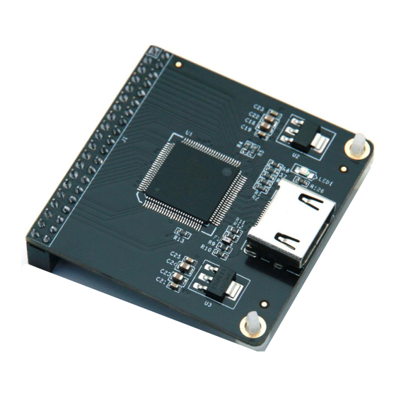
- Page 3 HDMI Display Module AN9134 User manual Part 1: HDMI Display Module General Description ALINX HDMI Display Output Module AN9134, use SIL9134 HDMI(DVI) coding chip of Silion Image Incorporation. Supports maximum 1080P@60Hz output and 3D output。 The module reserves a 40-pin female header that to connect FPGA development kit, a...
- Page 4 HDMI Display Module AN9134 User manual 1.1 AN9134 Module Detail Parameter HDMI display module detail parameter listed in below: HDMI coding chip:SiI9134 HDMI display channel:1-channel HDMI interface display standard:HDMI 1.4 Bus width: 24 bits RGB/YCbCr 4:4:4 ...
- Page 5 HDMI Display Module AN9134 User manual 1.2 AN9134 Module Parameter Description Figure 1-2: AN9134 Display Module Dimensions 5 / 13 www.alinx.com...
- Page 6 HDMI Display Module AN9134 User manual Part 2: HDMI Display Module Function Description 2.1 AN9134 Module Block Diagram Figure 2-1: AN9134 Module Block Diagram as below: Figure 2-1: AN9134 Module Block Diagram 2.2 AN9134 Module 40-pin Female Header Pins Description...
- Page 7 HDMI Display Module AN9134 User manual 9134_SDA 9134 I2C data 9134_D22 bit 22 of date input to module 9134_D23 bit 23 of date input to module 9134_D20 bit 20 of date input to module 9134_D21 bit 21 of date input to module...
- Page 8 +3.3V Part 3 HDMI Display Module Program Description We provide the HDMI driver programs of ALINX Series FPGA development board. In these driver demos, the FPGA drives the output display of SiI9134 by Internally generating HDMI timing and testing data.
- Page 9 HDMI Display Module AN9134 User manual the output clock timing of HDMI. Press the button KEY1 to switch the testing images. The function diagram of the testing programs (Figure 3-1) as below: Figure 3-1: The function diagram of the testing programs...
- Page 10 The 40-pin female headers of module plug into the expansion board of FPGA development kit, and then connect the HDMI connector to the monitor. The figure 4-1 is the expansion IOs J1 of ALINX Series FPGA development kit AX301 and the AN9134 HDMI module...
- Page 11 HDMI Display Module AN9134 User manual Figure 4-1: Hardware connection to ALINX Series FPGA Board Power on the FPGA development kit, download the programs, and then the 8-color vertical bar testing image display in HDMI monitor. Figure 4-2: 8-color vertical bar display in HDMI monitor 11 / 13 www.alinx.com...
- Page 12 HDMI Display Module AN9134 User manual Switch the testing image by press Button KEY1: Figure 4-3: Scrolling grayscale bar display in HDMI monitor Figure 4-4: colored gray bars display in HDMI monitor If the users to modify the output image resolution, just need to...
- Page 13 HDMI Display Module AN9134 User manual 1. an9134_test (Modify the resolution in the top file) Figure 4-5: Modify the resolution in top file 2. Modify the output clock frequency of PLL, the default output clock frequency is 1080P(148.5M), you need to modify the value marked in Figure 4-6.
Need help?
Do you have a question about the AN9134 and is the answer not in the manual?
Questions and answers