Table of Contents
Advertisement
Quick Links
Keysight N77xx Series
N7751A 1-Channel Optical Attenuator and Power Meter
N7752A 2-Channel Optical Attenuator and Power Meter
N7761A 1-Channel Optical Attenuator
N7762A 2-Channel Optical Attenuator
N7764A 4-Channel Optical Attenuator
N7766A 2-Channel Multimode Optical Attenuator
N7768A 4-Channel Multimode Optical Attenuator
User's Guide
Advertisement
Table of Contents

Related Manuals for Keysight Technologies N77 Series


Summary of Contents for Keysight Technologies N77 Series
- Page 1 Keysight N77xx Series N7751A 1-Channel Optical Attenuator and Power Meter N7752A 2-Channel Optical Attenuator and Power Meter N7761A 1-Channel Optical Attenuator N7762A 2-Channel Optical Attenuator N7764A 4-Channel Optical Attenuator N7766A 2-Channel Multimode Optical Attenuator N7768A 4-Channel Multimode Optical Attenuator User’s Guide...
- Page 3 Notices or any equivalent agency regulation THE MATERIAL CONTAINED IN THIS or contract clause. Use, duplication or © Keysight Technologies, Inc. 2015 DOCUMENT IS PROVIDED “AS IS,” disclosure of Software is subject to No part of this manual may be AND IS SUBJECT TO BEING Keysight Technologies’...
-
Page 4: Table Of Contents
Contents Contents Getting Started Overview Keysight N775xA Optical Attenuator and Power Meter and N776xA Optical Attenuator 10 Initial Inspection Safety Considerations Safety Considerations - Overview Safety Symbols General Operating Environment Line Power Requirements Input/Output Signals Line Power Connectors Instrument Markings AC Line Power Supply Requirements AC Line Power Supply Requirements - Overview Line Power Requirements... - Page 5 Front Panel Indicators Connecting to the Instrument Connecting to the Instrument - Overview Connecting over USB Finding the IP Address of an instrument Connecting over LAN Claims and Repackaging Claims and Repackaging Return Shipments to Keysight Technologies 43 Keysight N77xx Series...
- Page 6 Contents N77xx Viewer Common User Interface Functions Connecting to an Instrument Viewing Measurements Saving and Recalling Configurations Controlling the Instrument Refresh Attenuation Attenuation Controlling the Optical Attenuator Setting Attenuation Setting the Number of Digits displayed Selecting the Power Units Setting the Attenuation How to Remove Electrical Offsets (Zero) Enabling and Disabling the Output How to Set a Power Level...
- Page 7 Contents Accessories Accessories - Overview Instrument and Options - Keysight N7751A, N7752A, N7761A, N7762A, N7764A, N7766A, N7768A Cables Maintenance and Troubleshooting Maintenance and Troubleshooting - Overview Cleaning Instructions Cleaning Instructions Cleaning Instructions for this Instrument Safety Precautions Why is it important to clean optical devices? What do I need for proper cleaning? Preserving Connectors Cleaning Instrument Housings...
- Page 8 Contents Keysight N77xx Series...
-
Page 9: Getting Started
Keysight N77xx Series User's Guide Getting Started Overview This chapter helps you start using your N77-Series instrument. • “Keysight N775xA Optical Attenuator and Power Meter and N776xA Optical Attenuator” on page 10 • “Initial Inspection” on page 12 • “Safety Considerations - Overview” on page 13 •... -
Page 10: Keysight N775Xa Optical Attenuator And Power Meter And N776Xa Optical
1 Getting Started Keysight N775xA Optical Attenuator and Power Meter and N776xA Optical Attenuator The Keysight N775xA and N776xA are compact multichannel attenuators and power meters. They are a new class of remote- controlled fiber optic instruments. All attenuators feature power control functionality to set the output power level of the attenuator. - Page 11 Getting Started 1 The Keysight N7766A and the Keysight N7768A are optical attenuators for multimode fibers with two or four attenuator channels repectively. Both multimode attenuators are available with 50 micro-meter, 62.5 micro-meter, or 80 micro-meter-core multimode fibre. The N7766A and N7768A are 2 and 4 channel multimode fiber attenuators that are optimized for quick power setting and preservation of the input modal power distribution.
-
Page 12: Initial Inspection
If the contents are incomplete, mechanical damage or defect is apparent, or if an instrument does not pass the operator’s checks, notify the nearest Keysight Technologies Sales/Service Office. To avoid hazardous electrical shock, do not perform electrical tests when there are... -
Page 13: Safety Considerations
Keysight Technologies Inc. assumes no liability for the customer’s failure to comply with these requirements. This product has been designed and tested in accordance with IEC... -
Page 14: General
1 Getting Started The apparatus will be marked with this symbol when it is necessary for the user to refer to the instruction manual in order to protect the apparatus against damage. General This is a Safety Class 1 instrument (provided with a protective earth terminal) and has been manufactured and tested according to international safety standards. -
Page 15: Operating Environment
Getting Started 1 Operating Environment The instrument is not designed for outdoor use. To prevent potential fire or shock W A R N I N G hazard, do not expose the instrument to rain or other excessive moisture. Line Power Requirements The instrument complies with installation category II and can operate from the C A U T I O N single-phase AC power source that supplies between 100 V and 240 V at a frequency... -
Page 16: Input/Output Signals
1 Getting Started Input/Output Signals There is one input BNC connector: Trigger In. This is a TTL input. A maximum of 5 C A U T I O N V can be applied as an external voltage to this input connector. There is one output BNC connector: Trigger Out. -
Page 17: Instrument Markings
• Defective, damaged, or malfunctioning laser sources must be returned to an Keysight Technologies Service Center. Do not operate the instrument in the presence of flammable gases or fumes. Operation of any electrical instrument in such an environment constitutes a definite safety hazard. -
Page 18: Ac Line Power Supply Requirements
1 Getting Started The recycling symbol indicates the general ease with which the instrument can be recycled. Do not dispose in domestic household waste. To return unwanted products, contact your local Keysight office, or http://about.keysight.com/en/ companyinfo/environment/ takeback.shtml for more information. AC Line Power Supply Requirements AC Line Power Supply Requirements - Overview This secton provides information on:... - Page 19 Getting Started 1 Please note that the switch on the front panel of the instrument does not stop the C A U T I O N flow of power to the instrument. If you need to turn off the power, unplug the instrument at the mains or remove the power cable connector from the appliance coupler at the rear of the instrument.
-
Page 20: Changing The Fuse
There is no user replaceable fuse for the instrument. Changing the fuse should be C A U T I O N carried out only by Keysight Technologies service personnel. If you need to get the fuse replaced refer to your nearest Keysight Technologies Sales/Service Office. -
Page 21: Humidity
Getting Started 1 Humidity The operating humidity is 15 to 95%, non-condensing. Altitude The maximum operating altitude is 2000 m. Pollution Protection The instruments are designed for pollution degree 2. Instrument Cooling The instrument has a cooling fan mounted internally. Mount or position your instrument upright and horizontally, as shown in Figure 4 so that air can circulate through it freely. -
Page 22: Input And Output Connectors
1 Getting Started Figure 4 Correct Operating Position (shown here for the Keysight N7744/5A, valid also for the N7751/2A and Keysight N7761/2/4A, N7766/68A and the N7711/4A) Input and Output Connectors Input and Output Connectors - Overview This section provides information on: •... -
Page 23: Front Panels - Optical Attenuators
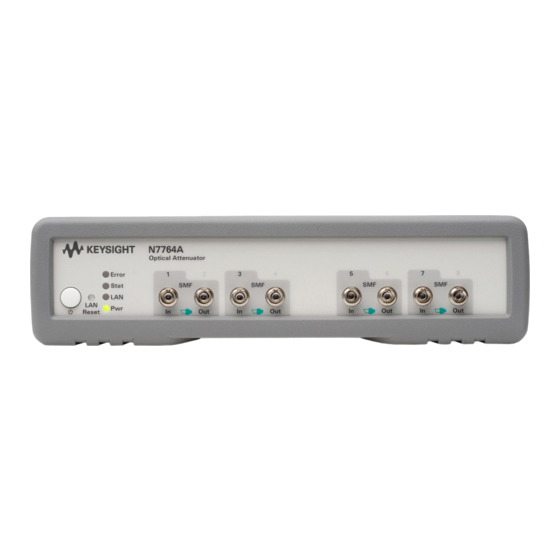
Getting Started 1 Front Panels - Optical Attenuators Figure 5 Front panel of the Keysight N7751A 1-Channel Optical Attenuator and 2-Channel Power Meter Keysight N77xx Series... - Page 24 1 Getting Started Figure 6 Front panel of the Keysight N7752A 2-Channel Optical Attenuator and 2-Channel Power Meter Figure 7 Front panel of the Keysight N7761A 1-Channel Optical Attenuator Figure 8 Front panel of the Keysight N7762A and N7766A 2-Channel Optical Attenuator Figure 9 Front panel of the Keysight N7764A and N7768A 4-Channel...
-
Page 25: Rear Panel
Getting Started 1 Rear Panel Figure 10 Rear panel of the Keysight N7744/5A Optical Multiport Power Meter, Keysight N7751/2A Optical Attenuator and Power Meter, and Keysight N7761/2/4/6/8A Optical Attenuator and Keysight N7711/4A Tunable Laser System Source Keysight N77xx Series... -
Page 26: Making Optical Connections
1 Getting Started Making Optical Connections Making Optical Connections The optical attenuators are designed for use with FC connectors. Attenuators ordered with option 021 have straight connector interfaces. Attenuators ordered with option 022 have angled connector interfaces. The N7751/2A power meters also use FC connectors but are non- contact. - Page 27 Getting Started 1 You should connect straight contact fiber end connectors with neutral sleeves to straight contact connectors, or connect angled contact fiber end connectors with green sleeves to angled contact connectors. “Accessories - Overview” on page 79 for further details on connector interfaces and accessories.
-
Page 28: Electrical Connectors
1 Getting Started Electrical Connectors There are two BNC connectors on the rear panel of your instrument. These are the Trigger Out and the Trigger In connectors. The Trigger In is a TTL input. A maximum of 5 V can be applied as an external voltage C A U T I O N to this input connector. -
Page 29: Lan Interface
Getting Started 1 LAN Interface LAN Interface This section explains the concept of LAN in details. Selecting a LAN Network For the purposes of this guide, a private (isolated) LAN network is defined as a network configuration in which instrument access is a direct connection between the computer and the instrument, or to multiple instruments connected via a dedicated router or switch. -
Page 30: Private Lan Considerations
1 Getting Started Private LAN Considerations Among the basic parameters of a private LAN network to consider are security, performance, reliability, and IP address availability. Security A private network generally involves a direct connection between the computer and the instrument, or to multiple instruments using switches or routers. -
Page 31: Reliability
Getting Started 1 Reliability Private networks are fundamentally more reliable than site networks as they host fewer users and are less complex than site networks. Private networks are isolated from conditions that could bring down (crash) a site network. IP Address Availability Every instrument (node) on a LAN (private or site) has an IP (Internet Protocol) address. - Page 32 1 Getting Started Figure 15 Typical Private (isolated) LAN Network Connections If the instrument is connected directly to the PC, use a LAN crossover cable, as provided with the instrument. If your computer supports Auto- MDIX or contains a LAN card with gigabit data transfer rates, the (blue) crossover cable is not required.
- Page 33 Getting Started 1 On site networks, the instrument and the computer are connected directly to site LAN ports, or are connected to the site LAN through a switch. In each site network configuration, standard LAN cables are used. The LAN LED As the LAN connection is made, the DHCP server assigns an address and the LXI device identification proceeds you will see the following indicators:,...
-
Page 34: Gpib Interface
1 Getting Started GPIB Interface GPIB Interface You can connect your GPIB interface into a star network, a linear network, or a combination star and linear network. The limitations imposed on this network are as follows: • The total cable length cannot exceed 20 meters. •... -
Page 35: Gpib Logic Levels
Getting Started 1 Keysight Technologies products delivered now are equipped with connectors C A U T I O N having ISO metric-threaded lock screws and stud mounts (ISO M3.5×0.6) that are black in color. Earlier connectors may have lock screws and stud mounts with English-threaded lock screws and stud mounts (6-32 UNC) that have a shiny nickel finish. -
Page 36: Powering Up The Instrument
1 Getting Started Powering Up the Instrument Powering Up the Instrument When you switch on the instrument, the LEDs on the front panel show the various stages of booting. Figure 19 Powering Up the Instrument Front Panel Indicators During operation, you may notice the following LED indicators: Figure 20 Front Panel Indicators Keysight N77xx Series... -
Page 37: Connecting To The Instrument
Getting Started 1 Connecting to the Instrument Connecting to the Instrument - Overview When you are first connecting the instrument, we recommend you use the Keysight Connection Expert included with the Keysight I/O libraries (available on the CD supplied with the instrument, or from www.keysight.com). -
Page 38: Finding The Ip Address Of An Instrument
1 Getting Started When the instrument is connected, it is shown in the list. Figure 22 Select the instrument in the list 3 Select the instrument in the list to see the associated tasks (in the Task Guide on the left) and information (on the right). Finding the IP Address of an instrument 1 Connect to the instrument over USB, as described above. - Page 39 Getting Started 1 3 Click on “Send commands to this instrument”. The default command is the *IDN? query. Figure 24 *IDN? query 4 Enter the command :SYSTem:COMMunicate:ETHernet:IPADdress:CURRent? then click on [Send & Read]. The instrument returns its current IP address. Figure 25 :SYSTem:COMMunicate:ETHernet:IPADdress:CURRent? Keysight N77xx Series...
-
Page 40: Connecting Over Lan
1 Getting Started Connecting over LAN The screenshots show the Keysight N7745A Multiport Power Meter. The same N O T E procedure applies when connecting to other N77xx instruments like attenuators and laser sources. 1 Make sure the instrument is connected to the LAN, and that the LAN LED on the front panel is green. - Page 41 Getting Started 1 Figure 27 7 To show the description of the N775xA or N776xA, check the box for *IDN? query and click on "Find Again". Figure 28 Keysight N77xx Series...
- Page 42 1 Getting Started 8 Select the instrument in the list to see the associated tasks (in the Task Guide on the left) and information (on the right). • For the N774x Multiport power meters, click on the “Instrument Web Interface” button to control the instrument directly. Figure 29 If it is not already installed, you will need to install a Java run-time engine to use this page.
-
Page 43: Claims And Repackaging
Return Shipments to Keysight Technologies If the instrument is to be shipped to an Keysight Technologies Sales/Service Office, attach a tag showing owner, return address, model number and full serial number and the type of service required. -
Page 44: N77Xx Viewer Common User Interface Functions
1 Getting Started 1 Press and hold the Reset/standby button until the instrument starts to reboot. 2 When the instrument reboots, press the Reset/standby button once more briefly, to confirm you want to delete all the stored data. N77xx Viewer Common User Interface Functions Connecting to an Instrument When you first launch the N77xx Viewer, it is not connected to any of your instruments. - Page 45 Getting Started 1 3 The list shows instruments that have been given a VISA address. If your instrument is not in the list, 1 Use the Keysight Connection Expert to check your instrument has a VISA address 2 Click on the “Scan Again” button. Once communication has been established to the instrument, its details are shown.
-
Page 46: Viewing Measurements
1 Getting Started – Make sure both DHCP and Auto IP are not selected. – You can now edit the IP parameters. 5 For instruments you use regularly, you can add a link on your desktop by putting a check mark in the box to “Place a shortcut on the Desktop”. -
Page 47: Saving And Recalling Configurations
Getting Started 1 Viewing all measurements 1 Click on Overview to open a window with the measurements on all channels. Figure 33 Viewing all measurements Saving and Recalling Configurations Saving a configuration You can save the current measurement configuration to either of two settings stored on the instrument. -
Page 48: Controlling The Instrument Refresh
1 Getting Started Recalling a configuration 1 In the File menu, select Load. 2 Enter or select the setting you want to retrieve. 3 Click on the “OK” button. Controlling the Instrument Refresh 1 In the File menu, select Update. In the dialog, you can : Figure 35 Controlling the Instrument Refresh... -
Page 49: Attenuation
Keysight N77xx Series User's Guide Attenuation Attenuation This chapter describes how to use the Keysight N7751A and N7752A Optical Attenuator and Power Meter, the Keysight N7761A, N7762A, and N7764A Single Mode Fiber Optical Attenuator and the Keysight N7766A and N7768A multimode fiber Optical Attenuators to attenuate and control optical power. - Page 50 2 Attenuation Figure 36 The Viewer The Viewer is available to download from the product webpage which you can access at http://www.keysight.com/find/voa Then select the tab “Technical Support” followed by “Drivers & Software”. Keysight N77xx Series...
-
Page 51: Setting Attenuation
Attenuation 2 Figure 37 Technical Support N7744A On this webpage you will also find additional software tools like: • Firmware update utility • Firmware update file • VXI Plug&Play Drivers Setting Attenuation Setting the Number of Digits displayed When the power is displayed with the Viewer program, you can set the maximum number of digits that are used in power measurement. -
Page 52: Setting The Attenuation
2 Attenuation Setting the Attenuation Before applying an attenuation factor, set the Attenuator module to the appropriate wavelength. The instrument uses a filter technology with a low wavelength dependence. Nevertheless, for the best possible accuracy: • If the source is of a particular wavelength, set the Attenuator module to that wavelength. -
Page 53: How To Remove Electrical Offsets (Zero)
Attenuation 2 The N7766A and N7768A multimode attenuators accept controlled speeds between 0.1 and 80 dB/s and a full speed of about 1000 dB/s. Settings above 80 dB/s will result in full-speed operation. How to Remove Electrical Offsets (Zero) The optical power meters in the attenuator measure optical power by converting optical power to electrical current, and then measuring electrical current. - Page 54 2 Attenuation Figure 38 How to Remove Electrical Offsets (Zero) 2 Select the channel you want to zero from the drop down list and click on the “This” button. Click on the “All” button. While the zero function is running, the traffic light flashes amber. If you receive a zero error, the zeroing operation has failed because the power meter received light.
-
Page 55: Enabling And Disabling The Output
Attenuation 2 Enabling and Disabling the Output You can turn on and off the attenuator output both for protection purposes or to simulate channel drops. Select or deselect the <Output>. • When the “Output” box is checked, the output is on. •... -
Page 56: How To Set The Wavelength
2 Attenuation Before taking a power measurement, make sure the source is warmed up so that N O T E its power output is stable. 1 Measure the insertion loss of the components between the attenuator output and the DUT, using a reference power meter. 2 Enter the result into the P Offset parameter. - Page 57 Attenuation 2 Figure 39 Extrapolation and Interpolation of Offset Values • If the operating wavelength matches a wavelength stored in the Offset Table, the exact offset value is used. • If the operating wavelength is between two wavelengths stored in the Offset Table, the offset applied is calculated by linear interpolation.
- Page 58 2 Attenuation To apply the offset table, click on “Set to N77xx” button, to save it to the attenuator for use. 5 Click on the “OK” button. Keysight N77xx Series...
-
Page 59: Specifications And Regulations Compliance
Keysight N77xx Series User's Guide Specifications and Regulations Compliance Definition of Terms (Applicable) fiber type Connection type for which the specifications and characteristics apply (if not differently stated). Attenuation Difference (in dB) between “Total loss” (with any attenuation setting, “Total loss” on page 70) and “Insertion loss”... - Page 60 3 Specifications and Regulations Compliance Attenuation setting mode Operating mode where the user sets the desired attenuation. The power control function is deactivated in this mode (see also “Power setting mode” on page 66). Attenuation accuracy (uncertainty) The maximum possible difference (in dB) between the displayed “Attenuation”...
- Page 61 Specifications and Regulations Compliance 3 Constant operating conditions This generally includes constant values of temperature, humidity, wavelength, input power level, polarization state and mode distribution, if the quantity is not explicitly subject to variation. Drift (dark) Specifies the maximum deviation from zero of the measured power with no optical input (dark) over time, excluding “Noise pp (dark)”...
- Page 62 3 Specifications and Regulations Compliance Insertion loss Specifies the “Total loss” at a displayed attenuation of 0 dB Conditions: Temperature range, wavelength range, source polarization input polarization, input mode (multimode attenuators only) as specified. Measurement: With Fabry-Pérot Laser Source, polarization controller (if applicable) and power meter, using high quality connectors in perfect optical condition.
- Page 63 Specifications and Regulations Compliance 3 Maximum safe (input) power The maximum input power that can be applied to any port of the power meter or attenuator without permanent change to its characteristics. Attention: Applying more than the specified power might damage the power meter or attenuator! For input powers >...
- Page 64 3 Specifications and Regulations Compliance Measurement: As for “Drift (dark)”. From the measured Pi and the fitted curve F the noise curve N is calculated. The noise N is N = max } - min Note: The noise pp specification (rather than noise 2 sigma) is given for legacy N O T E reasons.
- Page 65 Specifications and Regulations Compliance 3 Optical path blocking Maximum possible attenuation. Polarization dependent loss (PDL) The dependence of the “Total loss” (see, “Total loss” on page 70) on the input polarization state, expressed as the full difference (in dB) between the highest and the lowest total loss. Conditions: Temperature range, input mode as specified.
- Page 66 3 Specifications and Regulations Compliance Power range Specifies the range from the smallest input power that causes a significant change of the measured (displayed) power to the highest power for which the specifications apply if not differently stated. Measurement: The lower limit corresponds to half the "Noise pp (dark)"...
- Page 67 Specifications and Regulations Compliance 3 Relative uncertainty of monitor power meter When changing the output power of the attenuator, the relative power meter uncertainty is the maximum error of the displayed output power ratio to the actual output power ratio. This uncertainty is caused by the internal power meter's nonlinearity and noise and by errors in the sensing hardware, expressed as ±...
- Page 68 3 Specifications and Regulations Compliance and resetting the attenuation or power level. The repeatability is defined as ± half the difference between the highest and the lowest measured attenuation or power level over the repeated changing and resetting of the attenuation or power level. Figure 43 Repeatability Conditions: Constant operating conditions.
- Page 69 Specifications and Regulations Compliance 3 Settling Time Maximum time needed to change the attenuation or power level by a specified step, from the beginning until the end of the change. Specification wavelength range The wavelength range for which all specifications and characteristics apply, if not differently stated.
- Page 70 3 Specifications and Regulations Compliance Storage conditions Allowed temperature and humidity range for the non-operating instrument. Wait for acclimation to within the “Operating temperature” before turning on the instrument. Total loss The change of power level after inserting the attenuator between two connectorized patchcords, at an arbitrary attenuation setting, expressed in dB.
-
Page 71: Literature
Specifications and Regulations Compliance 3 Total uncertainty The maximum relative difference U between measured (displayed) power M and actual (true) power P for a specified set of operating conditions, expressed in percent. Powers expressed in Watts. Excluding "Noise pp (dark)" (see, “Noise pp (dark)”... -
Page 72: Technical Specifications - Optical Variable Attenuator And Power Meter
3 Specifications and Regulations Compliance Keysight N77xx Series... - Page 73 Specifications and Regulations Compliance 3 Keysight N77xx Series...
-
Page 74: Optical Power Meter
3 Specifications and Regulations Compliance Keysight N77xx Series... -
Page 75: General Characteristics
Specifications and Regulations Compliance 3 Keysight N77xx Series... -
Page 76: Declarations Of Conformity - Optical Multiport Attenuator And Power Meter
3 Specifications and Regulations Compliance Declarations of Conformity - Optical Multiport Attenuator and Power Meter The latest version of the Declaration of Conformity can be found here http://www.keysight.com/go/conformity Keysight N77xx Series... -
Page 77: Regulations Information
Specifications and Regulations Compliance 3 Regulations Information EMC Canada These ISM devices comply with Canadian ICES-001. Ces appareils ISM sont conformes à la norme NMB-001 du Canada. Acoustic Noise Information Germany ISO 7779 L < 70 dB(A), normal operation, operator position. Remove all doubt Remove all doubt Our repair and calibration services will get your equipment back to you,... -
Page 78: Keysight Direct
LXI is the LAN-based successor to GPIB, providing faster, more efficient connectivity. Keysight is a founding member of the LXI consortium. www.lxistandard.org www.keysight.com For more information on Keysight Technologies products, applications and services, please contact your local Keysight office. The complete list is available at: www.keysight.com/find/contactus... -
Page 79: Accessories
Keysight N77xx Series User's Guide Accessories Accessories - Overview The instruments are available in various configurations for the best possible match to the most common applications. This chapter provides information on the available options and accessories. -
Page 80: N7764A, N7766A, N7768A
4 Accessories Keysight N77xx Series... -
Page 81: Cables
Accessories 4 • • • • • GPIB Adapter, 10834A, 2.3 cm extender. Use this adapter if there is no space to connect your GPIB cable directly to a GPIB interface. • USB Cable, 8121-1243, 2 m (6.6 feet) • Cross-over LAN cable, 5061-0701, 2.1 m (7 feet) Keysight N77xx Series... - Page 82 4 Accessories Keysight N77xx Series...
-
Page 83: Maintenance And Troubleshooting
If you are unsure of the correct cleaning procedure for your optical device, we recommend that you first try cleaning a dummy or test device. Keysight Technologies assume no liability for the customer’s failure to comply with these requirements. -
Page 84: Cleaning Instructions For This Instrument
5 Maintenance and Troubleshooting Cleaning Instructions for this Instrument The Cleaning Instructions apply to a number of different types of Optical Equipment. Most relevant for this instrument is the section “How to clean connector adapters” on page 93 for cleaning the quad- adapters, and “How to clean optical glass plates”... -
Page 85: What Do I Need For Proper Cleaning
• Compressed air Dust and shutter caps All of Keysight Technologies’ lightwave instruments are delivered with either laser shutter caps or dust caps on the lightwave adapter. Any cables come with covers to protect the cable ends from damage or contamination. - Page 86 5 Maintenance and Troubleshooting If you need further dust caps, please contact your nearest Keysight Technologies sales office. Isopropyl alcohol This solvent is usually available from any local pharmaceutical supplier or chemist's shop. If you use isopropyl alcohol to clean your optical device, do not immediately dry the surface with compressed air (except when you are cleaning very sensitive optical devices).
- Page 87 Maintenance and Troubleshooting 5 We recommend that you do not use normal cotton tissues, but multi- layered soft tissues made from non-recycled cellulose. Cellulose tissues are very absorbent and softer. Consequently, they will not scratch the surface of your device over time. Use care when cleaning, and avoid pressing on your optical device with the tissue.
- Page 88 5 Maintenance and Troubleshooting some condensation or propellant. Such condensation leaves behind a filmy deposit. Please be friendly to your environment and use a CFC-free aerosol. Additional Cleaning Equipment Some Cleaning Procedures need the following equipment, which is not required to clean each instrument: •...
- Page 89 Maintenance and Troubleshooting 5 Warm water and liquid soap Only use water if you are sure that there is no other way of cleaning your optical device without corrosion or damage. Do not use hot water, as this may cause mechanical stress, which can damage your optical device.
-
Page 90: Preserving Connectors
Keep the caps on the equipment always when it is not in use. All of Keysight Technologies’ lightwave instruments and accessories are shipped with either laser shutter caps or dust caps. If you need additional or replacement dust caps, contact your nearest Keysight Technologies Sales/Service Office. -
Page 91: Which Cleaning Procedure Should I Use
Maintenance and Troubleshooting 5 cause damage to sensitive components, and in addition your warranty will be voided. Never open the instruments as they can be damaged. Opening the instruments puts you in danger of receiving an electrical shock from your device, and renders your warranty void. Which Cleaning Procedure should I use? Light dirt If you just want to clean away light dirt, observe the following procedure... - Page 92 5 Maintenance and Troubleshooting Never look into the end of an optical cable that is connected to an active source. W A R N I N G To assess the projection of the emitted light beam you can use an infrared sensor card.
-
Page 93: How To Clean Connector Adapters
Maintenance and Troubleshooting 5 How to clean connector adapters Preferred Procedure Use the following procedure on most occasions. 1 Clean the adapter by rubbing a new, dry cotton-swab over the surface using a small circular movement. 2 Blow away any remaining lint with compressed air. Procedure for Stubborn Dirt Use this procedure particularly when there is greasy dirt on the adapter: 1 Moisten a new cotton-swab with isopropyl alcohol. -
Page 94: How To Clean Optical Glass Plates
5 Maintenance and Troubleshooting How to clean optical glass plates The multiport power meter has an optical glass plate to protect the sensor. This has a special coating that is sensitive to solvents, grease, liquid and mechanical abrasion. Take extra care when cleaning this plate. -
Page 95: Other Cleaning Hints
Maintenance and Troubleshooting 5 4 Make your cleave and immediately insert the fiber into your bare fiber adapter in order to protect the surface from dirt. Other Cleaning Hints Selecting the correct cleaning method is an important element in maintaining your equipment and saving you time and money. This Appendix highlights the main cleaning methods, but cannot address every individual circumstance. -
Page 96: Error Messages
5 Maintenance and Troubleshooting Error Messages SYST:ERR? The syst:err? command returns the next error from the error queue (refer to the Programming Guide for details). Each error has an error code and a short description of the error, separated by comma. Please note that the error codes are returned as signed integer numbers in a range from -32768 to +32767 (INT16). - Page 97 Maintenance and Troubleshooting 5 1 Reset the instrument to factory default. a Send the command: SYSTem:PRESet b Press the LAN Reset button on the front panel briefly (<1 s). 2 Clear the instrument log. a Send the special command DIAG:SYST:FLAS:LOGF:ERAS The contents of the log can be checked with the query READ:LOGF?.
- Page 98 5 Maintenance and Troubleshooting Keysight N77xx Series...
-
Page 99: Index
Index Index Connector, 33 connectors, 98 Constant operating conditions, 61 Infrared sensor cards, 97 Accessories, 87 Initial Inspection, 7 Adapters, 33 Input/Output Signals, 15 Additional Cleaning Equipment, 93 Insertion loss, 63 Instrument Markings, 16 DRAM, 104 IP address, 29 Keysight N7751A, 8 Drift (dark), 61 Isopropyl alcohol, 94 Keysight N7752A, 8... - Page 100 Index Operating humidity, 65 Range in power setting mode, 70 Operating temperature, 65 Rear Panel, 24 Rear Panel, 21 Optical connectors, 25 Temperature for operation and Relative uncertainty of monitor power Optical attenuators, 25 storage, 19 meter, 71 Optical Equipment, 92 Total loss, 76 Repeatability (of attenuation/total loss, optical glass plate, 102...
- Page 101 Index Keysight N77xx Series...
- Page 102 This information is subject to change without notice. © Keysight Technologies 2015 Edition 7.0, January 2015 www.keysight.com...
Need help?
Do you have a question about the N77 Series and is the answer not in the manual?
Questions and answers