
Related Manuals for Keysight Technologies N774 C Series


Summary of Contents for Keysight Technologies N774 C Series
- Page 1 Keysight N774xC Series Multiport Power Meter N7744C 4-port Optical Power Meter N7745C 8-port Optical Power Meter User’s Guide...
- Page 2 CONTAINED HEREIN. SHOULD KEYSIGHT agreement and written consent from or commercial computer software AND THE USER HAVE A SEPARATE Keysight Technologies as governed by documentation that is not customarily WRITTEN AGREEMENT WITH WARRANTY United States and international copyright provided to the public; or (2) Relinquish to, TERMS COVERING THE MATERIAL IN THIS laws.
-
Page 3: Safety Summary
Failure to comply with these precautions or with specific warnings or operating instructions in the product manuals violates safety standards of design, manufacture, and intended use of the instrument. Keysight Technologies assumes no liability for the customer's failure to comply with these requirements. Product manuals are provided on the Web. -
Page 4: Instrument Markings
Instrument Markings Instrument Marking Description The instruction manual symbol. The product is marked with this warning symbol when it is necessary for the user to refer to the instructions in the manual. Standby supply. Unit is not completely disconnected from AC mains when switch is off. -
Page 5: Compliance And Environmental Information
Compliance and Environmental Information Table 1 Compliance and Environmental Information Safety Symbol Description This product complies with WEEE Directive (2002/96/EC) marking requirements. The affixed label indicates that you must not discard this electrical/electronic product in domestic household waste. Product Category: With reference to the equipment types in WEEE Directive Annex I, this product is classed as a “Monitoring and Control instrumentation”... - Page 6 Keysight N774xC Series Multiport Power Meter User’s Guide...
-
Page 7: Table Of Contents
Rack Mount the Instrument 2 Getting Started Initial Inspection Initial Inspection Claims and Repackaging Return Shipments to Keysight Technologies Deleting User Data Power Supply Requirements Line Power Requirements N774xC Series of Multiport Power Meters Keysight N774xC Series Multiport Power Meter User’s Guide... - Page 8 Contents Input and Output Connectors Optical Connections Making Quad-adapter Connections on the Keysight N7744/45C Multiport Power Meters Removing Quad-adapter Interfaces from the Keysight N7744/45C Multiport Power Meter Electrical Connectors LAN Interface The LAN LED The LAN Reset button USB Interface Powering Up the Instrument Connecting the Instrument Connecting over USB...
- Page 9 Contents 3 Definition of Terms Definition of Terms Specification Typical Value (Characteristics) Operating Conditions Specified Temperature Ambient Temperature Range (Applicable) fiber type Averaging time Constant operating conditions Data logging capability Drift (dark) Dynamic range (logging mode) Frequency Response Linearity Maximum safe (input) power Minimum averaging time Noise pp (dark) Noise 2 sigma (dark)
- Page 10 Contents Total uncertainty Uncertainty at reference conditions Wavelength range Warm-up time 4 User Interface Reference N774xC Series User Interface Controlling N774xC Instruments Control Instrument Tab How to Measure Power How to Set the Wavelength How to Set the Calibration Offset How to Set the Reference Level How to Remove Electrical Offsets (Zero) How to Choose the Range Mode...
- Page 11 Cleaning Instructions Safety Precautions Why is it important to clean optical devices? What materials do I need for proper cleaning? General Cleaning Procedure Additional Cleaning Information Firmware Upgrades Requirements Contact Keysight Technologies Keysight N774xC Series Multiport Power Meter User’s Guide...
-
Page 13: General Operating Considerations
Keysight N774xC Series Multiport Power Meter User’s Guide General Operating Considerations / 14 General Information / 15 Operating Environment / 17 Handling the Instrument... -
Page 14: General Information
Keysight Technologies assumes no liability for the customer’s failure to comply with these requirements. Ensure the proper usage for the instrument. The protection provided WARNING by the instrument may be impaired. -
Page 15: Operating Environment
General Operating Considerations Operating Environment Overview In order for the instrument to meet specifications, the operating environment must be within these limits. Refer to Safety Summary page 3. The instrument is not designed for outdoor use. To prevent potential fire WARNING or shock hazard, do not expose the instrument to rain or other excessive moisture. - Page 16 General Operating Considerations 75 mm (3 inches) 25 mm (1 inch) 25 mm (1 inch) Figure 1 Operating Position of the Instrument Keysight N774xC Series Multiport Power Meter User’s Guide...
-
Page 17: Handling The Instrument
General Operating Considerations Handling the Instrument Storage, Carrying and Shipment Keysight N7744C/5C multiport power meters can be stored, carried and shipped at temperatures between -40 C and +70 The N7744C/5C multiport power meters must be stored, carried in its operating position, as shown in Figure 1 Rack Mount the Instrument You can mount the instrument in a standard 19-inch rack cabinet using... - Page 18 General Operating Considerations B. Two Instruments Mounted on a Rack A. Single Instrument Mounted on a Rack Figure 2 Instrument(s) Mounted on a Rack Keysight N774xC Series Multiport Power Meter User’s Guide...
-
Page 19: Getting Started
Keysight N774xC Series Multiport Power Meter User’s Guide Getting Started / 20 Initial Inspection / 22 Power Supply Requirements / 26 Input and Output Connectors / 26 Input and Output Connectors / 28 Optical Connections / 30 Electrical Connectors / 31 LAN Interface / 33 Powering Up the Instrument... -
Page 20: Initial Inspection
Return Shipments to Keysight Technologies If the instrument is to be shipped to an Keysight Technologies Sales/ Service Office, attach a tag showing owner, return address, model number and full serial number and the type of service required. -
Page 21: Deleting User Data
Getting Started • Seal shipping container securely. • Mark shipping container FRAGILE to encourage careful handling. • In any correspondence, refer to instrument by model number and serial number. Deleting User Data If you need to delete all your logged data and user configurations, press and hold the LAN Reset button (approx. -
Page 22: Power Supply Requirements
Getting Started Power Supply Requirements Line Power Requirements Line Power Requirements The instrument complies with Overvoltage Category II and can operate from the single-phase AC power source that supplies between 100 V and 240 V at a frequency in the range 50/60 Hz. The maximum voltage fluctuation is 10% of the nominal supply voltage. - Page 23 Getting Started When the instrument is in stand-by mode, the Power LED is orange. When the instrument is powered-on, the Power LED is green. The AC power requirements are summarized on the rear panel of the instrument. Figure 4 AC Power Requirement Markings Keysight N774xC Series Multiport Power Meter User’s Guide...
-
Page 24: N774Xc Series Of Multiport Power Meters
Getting Started N774xC Series of Multiport Power Meters Keysight Technologies new N7744C and N7745C optical power meters with four or eight power-sensor channels provide manufacturing users with further increased throughput and operational efficiency to meet today’s challenges in multiple-device and multiport testing. A family-wide, common trigger concept, and a modern, browser accessible user interface, make it convenient to configure the instrument’s functionality. - Page 25 Getting Started These power meters are highly compatible with setups and programs. They are also easy to synchronize with Keysight tunable laser sources, to make spectral measurements. The functionality for time-dependent measurement has been extended with sampling at up to 1 MHz and data logging of up to 1 million samples for each port.
-
Page 26: Input And Output Connectors
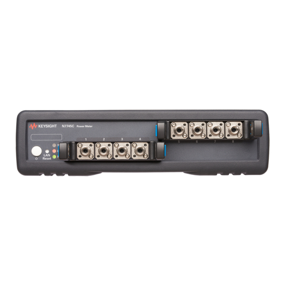
Getting Started Input and Output Connectors This section provides information on the front and rear panels of N774xC multiport power meters. Figure 5 shows the front panel of N7744C 4-port power meter. Figure 5 Front Panel of the N7744C 4-port power meter Figure 6 shows the front panel of N7745C 8-port power meter. - Page 27 Getting Started Figure 7 shows the rear panel of N7744/45C series multiport power meter: Figure 7 Rear Panel of the N7744/45C series multiport power meter Keysight N774xC Series Multiport Power Meter User’s Guide...
-
Page 28: Optical Connections
Getting Started Optical Connections The N774xC power meters do not make contact to the fiber connector faces and can be used with either angled or straight polished connectors. The N7744C and N7745C use the quad-adapters described below. When using bare fiber connections to power meters, the length of fiber CAUTION extending from the fiber holder must be carefully adjusted to avoid scratching the power meter optics. -
Page 29: Removing Quad-Adapter Interfaces From The Keysight N7744/45C Multiport Power Meter
Getting Started To use a quad-adapter to connect optical fibers to the power meter inputs: Select the quad-adapter that suits the optical connector that your optical fiber is terminated with. Attach the optical connectors to the quad-adapter. You can attach up to 4 fibers to the quad-adapter at the same time. -
Page 30: Electrical Connectors
Getting Started Electrical Connectors There are two BNC connectors on the rear panel of your instrument. These are the Trigger Out and the Trigger In connectors. The Trigger In is a TTL input. A maximum of 5 V can be applied as an CAUTION external voltage to this input connector. -
Page 31: Lan Interface
Getting Started LAN Interface The LAN LED When the LAN connection is made, you will see the following indicators: LAN link No IP Address No LAN link LAN link Yellow Green There may be a delay between making the LAN link (yellow status) and getting the IP address (green status). -
Page 32: Usb Interface
Getting Started USB Interface It is recommended to use the Keysight IO Libraries Suite to enable NOTE instrument communication for a variety of development environments. It is available at: http://keysight.com/find/iolibs The instrument is a USB device, with a USB Type-B connector which is available on the rear side of the instrument. -
Page 33: Powering Up The Instrument
Getting Started Powering Up the Instrument When you power on the instrument, the LEDs on the front panel show the various stages of the instrument. Power Status Yellow Standby mode Searching for LAN Warming Up Green Connected with LAN Blinking Green Communicating over LAN / USB Not connected... -
Page 34: Connecting The Instrument
Getting Started Connecting the Instrument Connecting over USB Power on the instrument. Connect the PC to the instrument using a USB cable. The operating system will detect and display the new instrument as a new drive. Double-click on this new drive. It will show a shortcut to start the user interface. -
Page 35: Connecting Over Lan
Getting Started Connecting over LAN Make sure the instrument is connected to the LAN, and that the LAN LED on the front panel is green. If it is not already running, start the Keysight Connection Expert software. The Discovery Service automatically discovers LAN instruments on the same subnet as the PC on which the service is running. - Page 36 Getting Started To manually add LAN instruments outside of the local subnet: a Click, select LAN Instrument from the context list. This opens the list of discovered LAN instruments. b Click the Enter Address tab. c Enter the LAN address or host name and select the protocol used to communicate with the instrument.
- Page 37 Getting Started Linux or macOS can use the zeroconf / mdns discovery service with tools like Avahi (GNU/Linux) or Bonjour (Mac). Keysight N774xC Series Multiport Power Meter User’s Guide...
-
Page 38: N774Xc User Interface
Getting Started N774xC User Interface Figure 10 depicts an example of N7745C multiport power meter user interface that displays the instrument’s connection settings. The below figure is also valid for N7744C multiport power meter. Figure 10 N774xC User Interface For details on the N7744/45C user interface and how to use it to control the instrument, refer to User Interface Reference on page 51. - Page 39 Keysight N774xC Series Multiport Power Meter User’s Guide Definition of Terms / 41 Specification / 41 Typical Value (Characteristics) / 41 Operating Conditions / 41 Specified Temperature / 41 Ambient Temperature Range / 41 (Applicable) fiber type / 42 Averaging time / 42 Constant operating conditions / 42...
- Page 40 Definition of Terms / 47 Return loss / 48 Specification wavelength range / 48 Spectral ripple (power meter; due to interference) / 48 Storage conditions / 48 Total uncertainty / 49 Uncertainty at reference conditions / 49 Wavelength range / 49 Warm-up time Keysight N774xC Series Multiport Power Meter User’s Guide...
-
Page 41: Definition Of Terms
Definition of Terms Definition of Terms This section defines terms that are used in this document. Specification Describes warranted product performance that is valid under the specified conditions. Specifications include guard bands to account for the expected statistical performance distribution, measurement uncertainties, changes in performance due to environmental changes and aging of components. -
Page 42: Averaging Time
Definition of Terms Averaging time Specifies the period during which the power meter or monitor power meter takes readings from the photo-detector. The displayed power result is the (arithmetical) average of these readings. Constant operating conditions This generally includes constant values of temperature, humidity, wavelength, input power level, polarization state and mode distribution, if the quantity is not explicitly subject to variation. -
Page 43: Dynamic Range (Logging Mode)
Definition of Terms Dynamic range (logging mode) For a fixed power meter range, dynamic range D specifies the difference between the maximum displayable value P in dBm in the corresponding power meter range and the minimum measurable power P in dBm. Conditions: As specified. -
Page 44: Maximum Safe (Input) Power
Definition of Terms Maximum safe (input) power The maximum input power that can be applied to any port of the power meter or attenuator without permanent change to its characteristics. Attention: Applying more than the specified power might damage the power meter or attenuator. -
Page 45: Operating Humidity
Definition of Terms Measurement: As for "Drift (dark)" (see, Drift (dark) on page 42). From the measurement result P and the fitted curve F the noise N is calculated by N = 2*StDev }, where StDev {} denotes the standard deviation over indices i. -
Page 46: Port Separation (Static)
Definition of Terms Port separation (static) Specifies the difference between the power P applied to one port and the measured power D on any other port with no applied power (dark). Excluding "Noise pp (dark)" (see, Noise pp (dark) on page 44) and "Drift (dark)"... -
Page 47: Range Settling Time (One Range Step)
Definition of Terms Range settling time (one range step) When changing from one power meter range to the next (one range higher or lower), the settling time specifies the time required for the power meter to settle into the new range. Measurements starting after that period are within specifications. -
Page 48: Specification Wavelength Range
Definition of Terms Specification wavelength range The wavelength range for which all specifications and characteristics apply, if not differently stated. Spectral ripple (power meter; due to interference) A coherent input signal causes optical interference1 between reflective interfaces within the power meter's optical assembly, including the end face of a connected fiber. -
Page 49: Uncertainty At Reference Conditions
Definition of Terms Uncertainty at reference conditions The maximum relative difference U between measured (displayed) power M and actual (true) power P for the specified set of reference conditions, including all uncertainties in the calibration chain from the national calibration laboratory to the test meter, expressed in percent. Powers expressed in Watts. -
Page 51: User Interface Reference
Keysight N774xC Series Multiport Power Meter User’s Guide User Interface Reference / 52 N774xC Series User Interface / 54 Controlling N774xC Instruments / 67 How to Use Auxiliary Functions... -
Page 52: N774Xc Series User Interface
User Interface Reference N774xC Series User Interface Figure 14 shows the N7745C user interface with various tabs highlighted. The same user interface is applicable for N7744C the instrument. Figure 14 N7745C User Interface The N774xC series user interface has the various tabs that help the user to control the N7744/45C instruments: •... - Page 53 User Interface Reference • Save/Recall – This tab allows you to save and load the user interface settings. For details, refer to How to Save/Recall the User Interface Settings? on page 68. • Configure LAN – This tab displays the current LAN configuration of the instrument.
-
Page 54: Controlling N774Xc Instruments
User Interface Reference Controlling N774xC Instruments Control Instrument Tab The Control Instrument tab displays the measured power of each channel of the N774xC instruments. When you launch the Control Instrument tab, by default, All Channel button is selected. This means that the user interface will show the measured power of all available (4 or 8) channels, depending upon the N774xC instrument type. - Page 55 User Interface Reference Display Wavelength and Power Displays the instrument’s current power, wavelength and power unit of the selected channel. For further details on power and it’s unit, refer to How to Measure Power on page 58. For further details on wavelength, refer to How to Set the Wavelength on page 59.
- Page 56 User Interface Reference Changing Wavelength and Power Unit Allows you to change the instrument’s current wavelength and the power units. The procedure for changing wavelength and power unit is similar. The following example provides steps to change the wavelength and the power unit.
- Page 57 User Interface Reference Show/Hide Marker To show/hide markers on the graph, go to Settings and then click Show/Hide Markers toggle button. When this button is enabled, the markers appear on the graph. The blue circle on the graph denotes the maximum power while the orange circle on the graph denotes the minimum power measure duration a given time interval.
-
Page 58: How To Measure Power
User Interface Reference Big Num If you are only interested in the measured numbers and not in the graphical view, you may exit the graph by clicking on the Big Num option. This option hides the graph and only the big sized measured numbers are displayed on the Control Instrument page. -
Page 59: How To Set The Wavelength
User Interface Reference Where, is the power value returned in dB, is the input signal level in Watts, and input Pref is the chosen reference power value in Watts. How to Set the Wavelength This is the wavelength value of the signal to be measured. The responsivity of the Power Meter varies with wavelength. -
Page 60: How To Set The Reference Level
User Interface Reference How to Set the Reference Level How to Input a Reference Level dB results are shown relative to a reference level. Setting, or changing, the reference only affects results that are returned in dB. You can set the reference level in units of dBm or Watts. Depending on which is selected the following equations are used to calculate the power level in dB: where,... - Page 61 User Interface Reference The power value in dBm or Watts is stored as the reference, that is: REF = P measured where, REF is the reference, and is the absolute power level (see How to Set the Calibration Offset measured on page 59).
-
Page 62: How To Remove Electrical Offsets (Zero)
User Interface Reference How to Remove Electrical Offsets (Zero) Optical Power Meters measure optical power by converting optical power to electrical current, and then measuring electrical current. An electrical offset is electrical current that is always present, even if there is no optical power input. -
Page 63: How To Choose The Range Mode
User Interface Reference Select the channel you want to zero from the drop down list and click on the Zero Port button. While the zero is running, the screen shows a 'busy' display. Click on the Zero First Quad button if you want to zero all channels from first quad. -
Page 64: How To Set The Range
User Interface Reference How to Set the Range The range setting determines the power levels that can be measured. The setting should be high enough for the applied power, but lower settings will provide a lower noise level for weak signals. If you choose auto-ranging mode, this parameter can not be set. -
Page 65: How To Set Automatic Gain For Averaging Modulated Signals
User Interface Reference specifications. These bandwidths are reduced in steps, when longer averaging times are used to improve the noise performance while maintaining signal fidelity. How to Set Automatic Gain for Averaging Modulated Signals A fast Auto Gain switching is used to achieve the high dynamic range in the N7744C and N7745C. - Page 66 User Interface Reference Set the input trigger functions The power meter ports can be configured individually to respond to an input trigger by: • Ignore (IGN) - The trigger is ignored. • Single Measurement (SME) - The trigger causes a single power measurement to be made.
-
Page 67: How To Use Auxiliary Functions
User Interface Reference How to Use Auxiliary Functions How to Get Current Instrument Settings? The Home tab on the N774xC user interface displays the current instrument settings. This tab displays the following settings: • Description – Displays the instrument description such as instrument’s model no., serial no., firmware version and description of the current instrument. -
Page 68: How To Identity A Module
User Interface Reference How to Identity a Module? Sometimes, you have many modules mounted on the rack. In this situation, it becomes difficult to identify a particular module which are currently connected. To identify a particular module, select the check-box Enable front panel identification indicator available on the N774xC Home tab. -
Page 69: Logging In/Out Of The N774Xc User Interface
User Interface Reference To perform the save/recall operation: Click on the Save/Recall tab. To save a file, click on Export button. The user interface settings will be saved as an XML file in your PC. To recall a previously saved file, click on Upload your XML file here button. -
Page 70: How To Create/Change The Password
User Interface Reference How to Create/Change the Password? The password is used for logging in to the web page to control the N774xC instruments. To create or change a password; Click the Password Options icon available on the top right of the N774xC user interface. -
Page 71: Reboot Device
User Interface Reference Enter the following details: • number of data points required on the graph, • refresh rates in milliseconds for the graph, and • refresh rates for the instrument settings. Click on Save button. The new refresh rates will only be effective for the current session. NOTE Reboot Device A firmware reboot is required if it becomes unresponsive or returns errors. -
Page 72: How To Configure Lan
User Interface Reference How to Configure LAN? Show the Current LAN Settings The Configure LAN tab on the N774xC user interface displays the currently used LAN settings. It display the following networking parameters: • IP address configuration • IP address •... - Page 73 User Interface Reference Your connection to the instrument may be broken after executing either WARNING of the operations below. If so, reconnect to the instrument using the new hostname or IP address. Enter the descriptions for the following LAN configuration parameters: •...
- Page 74 User Interface Reference Reset Network Configuration The Configure LAN tab also allows you to reset all LAN parameters to the factory default. To do so; Click the Advance Options button available on Configure LAN tab. The Advance Network Options page will appear. Click on the Reset button to reset all LAN parameters to the factory default.
- Page 75 Keysight N774xC Series Multiport Power Meter User’s Guide Maintenance / 76 Cleaning Instructions / 80 Additional Cleaning Information / 81 Firmware Upgrades / 82 Contact Keysight Technologies...
-
Page 76: Maintenance
If you are unsure of the correct cleaning procedure for your optical device, we recommend that you first try cleaning a dummy or test device. Keysight Technologies assume no liability for the customer’s failure to comply with these requirements. Safety Precautions Please follow the following safety rules: •... -
Page 77: What Materials Do I Need For Proper Cleaning
• Compressed air Dust and shutter caps All of Keysight Technologies’ lightwave instruments are delivered with either laser shutter caps or dust caps on the lightwave adapter. All cables come with covers to protect the cable ends from damage or contamination. - Page 78 Maintenance Do not use any other solvents, as some may damage plastic materials and claddings. Acetone, for example, will dissolve the epoxy used with fiber optic connectors. To avoid damage, only use isopropyl alcohol. If you use isopropyl alcohol to clean your optical device, do not immediately dry the surface with compressed air.
-
Page 79: General Cleaning Procedure
Maintenance Compressed air Compressed air can be purchased from any laboratory supplier. It is essential that your compressed air is free of dust, water and oil. Only use clean, dry air. If not, this can lead to filmy deposits or scratches on the surface of your connector. -
Page 80: Additional Cleaning Information
Maintenance Additional Cleaning Information For additional information on cleaning and safety matters for optical devices, refer the following document: https://literature.cdn.keysight.com/litweb/pdf/5989-4473EN.pdf Keysight N774xC Series Multiport Power Meter User’s Guide... -
Page 81: Firmware Upgrades
Maintenance Firmware Upgrades This section provides information about the firmware upgrade process for the N774xC multiport power meters instruments. You may need to upgrade firmware to enhance the usability and functionality of your instrument. New features may be available with new firmware revisions. -
Page 82: Contact Keysight Technologies
Check the firmware version. Go to instrument’s user interface Home tab and check for the firmware version. Contact Keysight Technologies To locate a sales or service office near you, go to www.keysight.com/find/contactus. Keysight N774xC Series Multiport Power Meter User’s Guide... - Page 84 This information is subject to change without notice. © Keysight Technologies 2020 Edition 1.1, July 2020 www.keysight.com...
Need help?
Do you have a question about the N774 C Series and is the answer not in the manual?
Questions and answers