Table of Contents
Advertisement
Quick Links
XPLR-AOA-3
Evaluation kit for ANT -B10 antenna boards
User guide
Abstract
Comprising an ANT-B10 antenna board, EVB-ANT-1 development platform, and C209 tag, the
XPLR-AOA-3 explorer kit provides a complete Angle of Arrival anchor point – and all you need for
developing direction-finding and indoor positioning applications.
This document describes the operation and assembly of the kit components and explains the
procedures for loading the u-connectLocate, EVB host, and tag software. It also includes a Quick
start guide to get the XPLR-AOA-3 up and running as quickly as possible.
UBX-22006906 - R03
C1-Public
0
0
3
Page 1 of 44
Advertisement
Table of Contents

Subscribe to Our Youtube Channel
Related Manuals for u-blox XPLR-AOA-3


Summary of Contents for u-blox XPLR-AOA-3
- Page 1 Abstract Comprising an ANT-B10 antenna board, EVB-ANT-1 development platform, and C209 tag, the XPLR-AOA-3 explorer kit provides a complete Angle of Arrival anchor point – and all you need for developing direction-finding and indoor positioning applications. This document describes the operation and assembly of the kit components and explains the procedures for loading the u-connectLocate, EVB host, and tag software.
-
Page 2: Document Information
The information contained herein is provided “as is”. No warranty of any kind, either express or implied, is made in relation to the accuracy, reliability, fitness for a particular purpose or content of this document. This document may be revised by u-blox at any time. -
Page 3: Table Of Contents
Contents Document information ........................2 Contents ..............................3 Quick start guide .........................5 Product description ........................6 2.1 Kit includes ................................6 2.2 Assembling the kit ............................. 7 ANT-B10 ............................8 3.1 Flashing ANT-B10 software ..........................9 3.1.1 General ................................9 3.1.2 Flashing using s-center ........................... 9 3.1.3 Flashing from the Command line ....................... - Page 4 u-connectLocate software...................... 29 6.1 General information ............................29 6.2 Configuration example............................ 29 Appendix ............................30 Glossary ............................30 C209 schematics ........................31 EVB-ANT-1 schematics ......................32 Related documentation........................44 Revision history ..........................44 Contact .............................. 44 UBX-22006906 - R03 Page 4 of 44 C1-Public...
-
Page 5: Quick Start Guide
Quick start guide Install s-center evaluation software s-center is a powerful and easy-to-use tool for evaluating, configuring, and testing u-blox short range modules. Running on Windows 10 operating systems, the software allows end users to configure and assess the performance of u-blox short range modules. -
Page 6: Product Description
Product description Comprising an ANT-B10 antenna board, EVB-ANT-1 development platform and C209 tag, the XPLR- AOA-3 explorer kit provides a complete Angle of Arrival anchor point – and all you need for developing direction-finding and indoor positioning applications. The antenna board runs proprietary u-connectLocate software, while the development board runs an open-source demonstration software that relays angle events from the antenna board. -
Page 7: Assembling The Kit
Figure 2 shows the location of the header connectors on each board. Figure 2: Assembled XPLR-AOA-3 kit showing EVB-ANT-1 and ANT-1 headers Using the supplied standoffs and screws, assemble the two PCBs to the plexiglass, as shown in Figure 3. The assembly order of the components (see... -
Page 8: Ant-B10
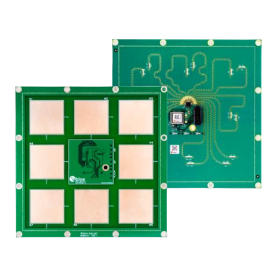
ANT-B10 ANT-B10 provides a versatile Bluetooth® direction finding board equipped with eight, dual-polarized, patch antennas for direction finding, as shown in Figure 4 Figure 5. Figure 4: ANT-B10 board – top view showing antennas, traces, and mounting holes Figure 5: ANT-B10 - bottom view showing NINA-B411 module, switch, and header UBX-22006906 - R03 Page 8 of 44 C1-Public... -
Page 9: Flashing Ant-B10 Software
For general information about Bluetooth direction finding, watch the u-blox webinars and study the Bluetooth SIG technical overview [3]. XPLR-AOA-3 contains the ANT-B10 board as well as an EVB-ANT-1 host board to facilitate convenient testing. ☞ For information about using the XPLR-AOA-3 kit for indoor positioning and the positioning engine client software for Windows, see also the Bluetooth indoor positioning guide [21]. -
Page 10: Flashing From The Command Line
Figure 6: Updating the software on the board using s-center 3.1.3 Flashing from the Command line Use the following procedure to flash the board over the UART connection. Download the u-connectLocate software container from the u-connectLocate product page [4]. Boot the board into Software Update mode by connecting the SWITCH_2 pin to ground while powering up the board. -
Page 11: Ant-B10 Configuration And Testing
3.2 ANT-B10 configuration and testing A green LED light indicates that the board is powered on. Having connected the COM port, the board is ready to receive AT commands. For information about the AT commands to use for configuring direction finding, see the u-connectLocate AT commands manual [18]. -
Page 12: Connecting To A Pc
Angle events can also be visualized in the s-center using the “IoT > Angle of Arrival” tab, as shown Figure Figure 7: s-center with Angle of Arrival tab 3.3 Connecting to a PC 3.3.1 Overview A host PC communicates with ANT-B10 over UART interface (TX, RX, CTS, RTS) through EVB-ANT-1. The pin-headers connecting the two boards together is physically located in the center of the each board. -
Page 13: Pin Description For Uart Connection
Attaching a USB-to-TTL serial adapter to the expansion board with an adjoining cable harness allows convenient access and control of the UART interface from the PC through the ANT-B10 header. Figure 8 shows the USB adapter attached to ANT-B10 through the standard 1.27 mm pin header. Figure 8: ANT-B10 with UART to USB serial converter ☞... -
Page 14: Suggested Accessories
Figure 9 shows the pin positions on the ANT-B10 connector. Figure 9: ANT-B10 connector pin assignment (top view) 3.3.3 Suggested accessories Figure 10 shows (from left to right) the components needed to connect ANT-B10 to the host PC. • USB adapter cable with male USB Type-A connector to male mini-B connector •... -
Page 15: Evb-Ant-1
The EVB-ANT-1 application board offers developers a quick and easy way to evaluate the ANT-B10 and ANT-B11 antenna boards. It features the NXP RT1061 Microcontroller Unit (MCU) for configuring and developing direction finding applications, as well as an Ethernet PHY chip and u-blox MAYA-W1 Wi-Fi module. -
Page 16: Introduction
4.1 Introduction EVB-ANT-1 is a versatile application board for evaluating a system setup, using the ANT-B10 board, or other antenna boards. The board can be used as: • an anchor point passing raw or processed angle events from the antenna board to a server •... -
Page 17: Custom Antenna Support
Direction finding data is then forwarded through the chosen communication interface – either Ethernet or Wi-Fi using the MAYA-W1 module. The highlighted areas in Figure 13 show the EVB-ANT-1 components involved in this use case. EVB-ANT-1 ANT-Bxx connector ANT-Bxx GPIO Ethernet connector Ethernet... - Page 18 The highlighted areas in Figure 14 show the EVB-ANT-1 components involved in this use case. EVB-ANT-1 ANT-Bxx connector ANT-Bxx GPIO Ethernet connector Ethernet UART connector (PoE+) Power UART controller DC Power FTDI USB FTDI connector UART connector SDIO Custom WiFi NINA-B4 MAYA-W1 Antenna...
-
Page 19: Uart Connections To Board
Figure 15: NINA-B4 connector to custom antenna board 4.4 UART connections to board EVB-ANT-1 supports a quad-channel UART interface that connects to: • • NINA-B411 module hosted on the ANT-Bxx • onboard NINA-B411 module hosted on EVK-ANT-B1 Figure 16: UART connections over USB UBX-22006906 - R03 Page 19 of 44 C1-Public... -
Page 20: Evb-Ant-1 Software
The UART connections on the ANT-Bxx and onboard NINA-B411 are connected to the MCU by default. It is possible to connect directly from the USB connector to either: • NINA-B411 hosted on the ANT-Bxx board (with jumper J12 removed) • onboard NINA-B411 (with jumper J11 removed) The connection options make it possible to perform software updates or configuration through the UART interface. -
Page 21: Boot Options
From the configuration interface, you can: • Configure network settings for Wi-Fi and ethernet. The default IP address of EVB-ANT-1 is 192.168.1.102. • Send UDP packets containing angle events generated by the anchor. It is often convenient to broadcast the address of the network, as shown in Figure •... -
Page 22: Mechanical Specifications
The powering options are controlled with jumper J2, as shown in Figure Figure 19: Jumper J2 powering options J2 jumper settings are described in Table Jumper position Pins Power setting 1–2 Power over Ethernet or barrel jack. When the barrel jack is present and connected to a voltage source, the device automatically gives priority to that, even if a PoE switch is also connected to the ethernet plug. -
Page 23: C209 Tag
C209 tag The C209 is a tag based on the NINA-B406 Bluetooth LE module. The tag runs software that sends Bluetooth 5.1 advertisement messages to the ANT-B10 antenna board, which determine the direction of the tag using the u-connectLocate software. See also C209 tag. - Page 24 C209 schematics. ☞ Although the sensors on the C209 application board are not used in the latest direction -finding tag software from u-blox, the sensors can be utilized in any customer application. UBX-22006906 - R03 Page 24 of 44 C1-Public...
-
Page 25: C209 Software And Flashing
UART interface with the boot loader. u-blox C209 tag software can be installed using the DFU bootloader or an external debugger. Precompiled packages for each installation option are available from the u-blox C209 software repository [12]. -
Page 26: Installing Tag Software On The Command Line With The Dfu Bootloader
5.2.2 Installing tag software on the command line with the DFU bootloader Install C209 tag software with the pre-flashed DFU bootloader on NINA-B406: Download and install the nrfutil flashing tool from the Nordic Github repository [15]. Download and unpack the file from the u-blox C209 software c209_aoa_tag_for_dfu_boot.zip repository using this direct link, or go to the “Releases”... -
Page 27: Configuration And Handling
5.3 Configuration and handling 5.3.1 Configuring advertising interval Press the SW2 button on the C209 to change the advertising interval. When SW2 is pressed, the advertising interval cycles through the available advertising intervals. For best performance, it is advisable to use the fastest advertising interval. The LED will blink shortly to indicate the advertising interval, with 1 blink indicating the fastest advertising. -
Page 28: Restore Eddystone Instance Id
5.3.3 Restore Eddystone Instance ID All u-blox modules are delivered with a u-blox MAC address, which is written into the UICR register. If the MAC address is accidentally erased, for example during a reflash of the software, this information is lost. If this happens, the Eddystone Instance ID transmitted in the C209 advertising beacon will not match the MAC address of the module. -
Page 29: U-Connectlocate Software
NINA-B411-40B module, which is connected to the antenna array and Bluetooth receiver on the ANT-B10 board. 6.2 Configuration example By default, u-connectLocate comes pre-configured to track all u-blox tags. The tags advertise with the Eddystone namespace , which by default is tracked in u-connectLocate. -
Page 30: Appendix
Appendix A Glossary Abbreviation Definition Angle of Arrival Angle of Departure ASCII American Standard Code for Information Interchange Arm (Advanced RISC Machines) Holdings Central Processing Unit Constant Tone Extension Microcontroller Unit Power over Ethernet RSSI Received Signal Strength Indication Table 6: Explanation of the abbreviations and terms used UBX-22006906 - R03 Page 30 of 44 C1-Public... -
Page 31: B C209 Schematics
B C209 schematics UBX-22006906 - R03 Page 31 of 44 C1-Public... -
Page 32: Cevb-Ant-1 Schematics
C EVB-ANT-1 schematics UBX-22006906 - R03 Page 32 of 44 C1-Public... - Page 33 UBX-22006906 - R03 Page 33 of 44 C1-Public...
- Page 34 UBX-22006906 - R03 Page 34 of 44 C1-Public...
- Page 35 UBX-22006906 - R03 Page 35 of 44 C1-Public...
- Page 36 UBX-22006906 - R03 Page 36 of 44 C1-Public...
- Page 37 UBX-22006906 - R03 Page 37 of 44 C1-Public...
- Page 38 UBX-22006906 - R03 Page 38 of 44 C1-Public...
- Page 39 UBX-22006906 - R03 Page 39 of 44 C1-Public...
- Page 40 UBX-22006906 - R03 Page 40 of 44 C1-Public...
- Page 41 UBX-22006906 - R03 Page 41 of 44 C1-Public...
- Page 42 UBX-22006906 - R03 Page 42 of 44 C1-Public...
- Page 43 UBX-22006906 - R03 Page 43 of 44 C1-Public...
-
Page 44: Related Documentation
[19] EVB-ANT-1 SW GitHub repository: https://github.com/u-blox/evb-ant-1 [20] Serial Downloader user guide, https://spsdk.readthedocs.io/en/latest/apps/sdphost.html [21] Bluetooth indoor positioning application note, UBX-21006395 ☞ For product change notifications and regular updates of u-blox documentation, register on our website, www.u-blox.com. Revision history Revision Date Name Comments...
Need help?
Do you have a question about the XPLR-AOA-3 and is the answer not in the manual?
Questions and answers