Table of Contents
Advertisement
Quick Links
EVK-NINA-B50
Evaluation kit for NINA-B50 modules
User guide
Abstract
This document describes how to set up the EVK-NINA-B50 evaluation kit to evaluate NINA-B50
series standalone Bluetooth
debugging and testing the development capabilities included in the evaluation board.
UBX-23007761 - R02
C1-Public
®
5.3 Low Energy modules. It also describes the different options for
www.u-blox.com
Advertisement
Table of Contents

Related Manuals for u-blox EVK-NINA-B50


Summary of Contents for u-blox EVK-NINA-B50
- Page 1 EVK-NINA-B50 Evaluation kit for NINA-B50 modules User guide Abstract This document describes how to set up the EVK-NINA-B50 evaluation kit to evaluate NINA-B50 series standalone Bluetooth ® 5.3 Low Energy modules. It also describes the different options for debugging and testing the development capabilities included in the evaluation board.
-
Page 2: Document Information
The information contained herein is provided “as is”. No warranty of any kind, either express or implied, is made in relation to the accuracy, reliability, fitness for a particular purpose or content of this document. This document may be revised by u-blox at any time. -
Page 3: Table Of Contents
Product description ..........................5 1.1 Overview ................................ 5 1.2 Kit includes ..............................6 1.3 Key features ..............................6 1.4 EVK-NINA-B50 block diagram ........................7 1.5 Connectors ..............................8 Setting up the evaluation board ....................... 9 2.1 Evaluation board setup ..........................9 2.2 Software Development .......................... - Page 4 EVK-NINA-B50 - User guide Glossary ..............................36 Related documents ........................... 37 Revision history ............................37 Contact ................................37 UBX-23007761 - R02 Contents Page 4 of 37 C1-Public...
-
Page 5: Product Description
EVK-NINA-B50 - User guide Product description 1.1 Overview The EVK-NINA-B50 evaluation kit is a versatile development and evaluation platform that allows quick prototyping of a variety of low-powered Internet of Things (IoT) applications, using Bluetooth 5.3 and IEEE 802.15.4. EVK-NINA-B50 boards are available in the following two variants that accommodate alternative antenna solutions: •... -
Page 6: Kit Includes
EVK-NINA-B50 - User guide EVK-NINA-B50 evaluation boards provide access to the 29 GPIO pins and interfaces that are supported on NINA-B50 modules. The interfaces are available through a variety of connectors, including the Arduino™ UNO R3 and Raspberry Pi header connectors. The boards also provide simple USB drag-n-drop programming and a SEGGER J-Link debug interface. -
Page 7: Evk-Nina-B50 Block Diagram
EVK-NINA-B50 - User guide 1.4 EVK-NINA-B50 block diagram Figure 3 shows the major interfaces and internal connections of the EVK-NINA-B50. Figure 3: EVK-NINA-B50 block diagram *Only supported on EVK-NINA-B506 UBX-23007761 - R02 Product description Page 7 of 37 C1-Public... -
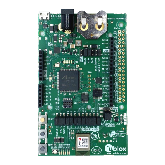
Page 8: Connectors
EVK-NINA-B50 - User guide 1.5 Connectors Table 1 describes the available connectors of the EVK-NINA-B50 shown in Figure Connector Function Description Power supply 2.1 mm power jack, the center pin is the positive terminal. 5–12 V input. Power supply Pin header that can be used to connect external power supplies. 5–12 V input. -
Page 9: Setting Up The Evaluation Board
⚠ Be careful to check polarity before connecting an external power supply to the EVK-NINA-B50 evaluation board. Center conductor is positive (+) and the ring is negative (-). The operating system installs the correct drivers automatically. The drivers need only to be installed once when you connect the unit to a new computer. -
Page 10: Measuring Current Consumption
EVK-NINA-B50 - User guide An external debugger is useful when powering the evaluation board with a CR2032 coin cell battery, or through the J5 external power supply connector. It is also useful when the MCU interface has been disconnected from the NINA-B50 module using the jumpers on the J19 header. - Page 11 EVK-NINA-B50 - User guide Figure 5: Different options when measuring NINA module current consumption UBX-23007761 - R02 Setting up the evaluation board Page 11 of 37 C1-Public...
-
Page 12: Board Configuration
Figure 6: Block diagram of the power net distribution Selecting the power configuration jumpers EVK-NINA-B50 offers flexible powering options for the NINA-B50 module and the board itself. To configure this, jumpers are added or removed to pin headers, shorting two of the pins together and connecting or disconnecting different power nets on the evaluation board. - Page 13 EVK-NINA-B50 - User guide Sources Net names Targets DC/DC VDD_MCU Onboard 3.3 V PC communication converter 3V3_PI VBAT Raspberry Pi expansion board Battery VBAT_DIODE VDD_IO Battery with Board I/O power: protection diode Level shifters, LEDs etc. -.-- V Any power net...
- Page 14 EVK-NINA-B50 - User guide Connector Pin no. Schematic net Description Regulated 3.3 V net. This net is supplied by the board and is always powered as long as a power source is connected. 3V3_PI Connects to the Raspberry Pi header’s (J 4) 3V3 pins. If a Raspberry Pi is connected, this net must be unconnected to prevent back currents.
-
Page 15: Default Power Configuration, 3.3 V
EVK-NINA-B50 - User guide Default power configuration, 3.3 V Figure 9 shows the default “out-of-the-box” power configuration for the evaluation board. In this configuration, all board peripherals are powered up and the NINA module is directly supplied by the board. Everything runs at 3.3 V. -
Page 16: Battery Powered, 3 -1.71 V
EVK-NINA-B50 - User guide Battery powered, 3 –1.71 V When using a battery, Figure 10 shows the default configuration. The battery voltage is connected to VDD_NINA, which in turn, is connected to the NINA-B50 VCC supply. If needed, a jumper can be added to J22, pins 2 and 4, to supply LEDs and other peripherals with power –... -
Page 17: Battery Powered With Protection Diode, 2.7-1.71 V
EVK-NINA-B50 - User guide Battery powered with protection diode, 2.7–1.71 V This use case is meant to protect the battery from current back surges. There is a risk that the applied electromagnetic field can cause back surges on the module’s power supply lines that typically damage a non-chargeable battery. -
Page 18: External Supply, 1.71- 3.60 V
EVK-NINA-B50 - User guide External supply, 1.71- 3.60 V When measuring current consumption or performing other NINA-B50 module characterization measurements, it can be useful to power the module with an external source such as a lab power supply. In such cases, all jumpers can be removed, and the required supply nets can be fed externally by connecting to the pin headers. -
Page 19: Raspberry Pi Hat
EVK-NINA-B50 - User guide Raspberry Pi HAT When connecting a HAT to the Raspberry Pi interface, use the jumper configuration shown in Figure 13. Depending on how the NINA module is to communicate with a test PC over USB or with the HAT, the VDD_MCU net could be left unpowered. - Page 20 EVK-NINA-B50 - User guide Figure 14: Jumper headers J19 and J9 that are used to isolate specific NINA signals Connector Pin no. Schematic net name Description RESET_N NINA reset signal, active low RESET_N_I Connects to the Interface MCU’s reset line...
-
Page 21: Interfaces And Peripherals
Connected to the NINA RED (GPIO_1), GREEN (GPIO_7) and BLUE (GPIO_8) pins through jumper header J19. ☞ See also the NINA-B50 data sheet [3]. Table 10: EVK-NINA-B50 LED indicators UBX-23007761 - R02 Interfaces and peripherals Page 21 of 37 C1-Public... -
Page 22: Arduino Interface
EVK-NINA-B50 - User guide 4.2 Arduino interface The EVK-NINA-B50 includes a set of pin headers and mounting holes that are compatible with certain Arduino or Arduino inspired shields. However, in EVK-NINA-B50 a reduced number GPIOs are available. ⚠ NINA-B50 is not fully compatible with Arduino due to reduced number of GPIOs. - Page 23 EVK-NINA-B50 - User guide Conn. Arduino Description NINA-B4 K32W Alternate functions and notes schematic net name* External DC supply input, 5 – 12 VDC VIN Analog input GPIO_25 PTA20 Analog function capable GPIO Analog input GPIO_24 PTC6 Analog function capable GPIO...
-
Page 24: Arduino Shield Compatibility
Arduino shield compatibility ☞ As EVK-NINA-B50 has an I/O voltage range of 1.71–3.60 V, it can only be used with shields that support an I/O voltage in this range. The EVK-NINA-B50 has a pinout that is compatible with some Arduino, or Arduino-inspired, shields... - Page 25 EVK-NINA-B50 - User guide Figure 17: Pin header J14 that is compatible with the Raspberry Pi GPIO connectors Conn. Pin no. Raspberry Pi pin Description K32W pin Alternate functions and notes NINA-B4 schematic net name* 3.3 V 3.3 V supply pin 3V3_PI Not connected by default.See...
- Page 26 EVK-NINA-B50 - User guide Conn. Pin no. Raspberry Pi pin Description NINA-B4 schematic K32W pin Alternate functions and notes net name* GPIO18 Digital I/O GPIO_1 PTA16 GPIO27 Digital I/O GPIO_52 PTB2 Connected to NINA through a solder bridge. If the solder bridge is cut this pin is left floating.
-
Page 27: Powering Considerations
EVK-NINA-B50 - User guide Powering considerations Two voltage nets are used in the Raspberry Pi interface, 3V3_PI and 5V. Both the 3V3_PI and 5V nets can be used to power HATs, but these nets should not be used when connecting to a Raspberry Pi. - Page 28 EVK-NINA-B50 - User guide Connector Pin no. Schematic net name K32W pin Description annotation SPI_CS/GPIO_51 PTB0 Chip select input signal, active low SPI_MISO/GPIO_48 PTB1 MISO in single SPI mode, or data I/O signal in dual/quad mode GPIO_49 PTC0 Ground SPI_MOSI/GPIO_50...
-
Page 29: Extra Memory - External Flash
EVK-NINA-B50 - User guide Extra memory – external Flash NINA-B50 series modules can accommodate extra memory outside of the module. The memory space can be used to store data and/or expand the application code size. NINA-B50 modules support an SPI (Serial Peripheral Interface) to communicate with the external flash memory. -
Page 30: Appendix
EVK-NINA-B4 schematics, which except for the module pin names and unsupported functionality are the same as the currently unavailable EVK-NINA-B50 schematics. The correlation between the signal names for EVK-NINA-B4 against those supported in EVK-NINA-... - Page 31 EVK-NINA-B50 - User guide ☞ All “crossed-out” circuits in the above schematic are associated with functionality supported in EVK-NINA-B4 but not supported in EVK-NINA-B50. Figure 21: Hub, FTDI and flash – schematic ☞ Pages 2 of the schematics are intentionally omitted.
- Page 32 EVK-NINA-B50 - User guide Figure 22: Headers and buttons - schematic UBX-23007761 - R02 Appendix Page 32 of 37 C1-Public...
- Page 33 EVK-NINA-B50 - User guide Figure 23: Power supply schematic ☞ All “crossed-out” circuits in the above schematic are associated with functionality supported in EVK-NINA-B4 but not supported in EVK-NINA-B50. ☞ Page 6 of the schematics is intentionally omitted. UBX-23007761 - R02...
-
Page 34: Nina-B4 To Nina-B50 Pin Correlation
EVK-NINA-B50 - User guide A.1 NINA-B4 to NINA-B50 pin correlation Table 16 describes the pin allocations for NINA-B50 against those for older NINA-B4 module shown in EVK-NINA-B4 schematics. No. Name NINA-B4 Description NINA-B4 Name NINA-B50 Description NINA-B50 GPIO_1 General purpose I/O... - Page 35 EVK-NINA-B50 - User guide No. Name NINA-B4 Description NINA-B4 Name NINA-B50 Description NINA-B50 33 TRACE_D3/GPIO_33 General purpose I/O RSVD Not connected 34 GPIO_34 General purpose I/O RSVD Not connected 35 GPIO_35 General purpose I/O RSVD Not connected 36 GPIO_36 General purpose I/O...
- Page 36 EVK-NINA-B50 - User guide B Glossary Abbreviation Definition Analog Digital Converter Application programming interface Clear To send Evaluation kit Ground GPIO General-Purpose Input/Output Light-Emitting Diode Micro controller unit Mass storage device U.FL Coaxial RF connector Universal serial bus Request To send...
- Page 37 [5] SEGGER J-Link software - https://www.segger.com/jlink-software.html [6] U-blox open CPU repository: https://github.com/u-blox/u-blox-sho-OpenCPU [7] FTDI chip home page: https://ftdichip.com/ ☞ For product change notifications and regular updates of u-blox documentation, register on our website, www.u-blox.com. Revision history Revision Date Name Comments...
Need help?
Do you have a question about the EVK-NINA-B50 and is the answer not in the manual?
Questions and answers