Table of Contents
Advertisement
Quick Links
EVK-LEXI-R520
LEXI-R520 cellular evaluation kit
User guide
Abstract
This guide explains how to set up the EVK-LEXI-R520 evaluation kit to begin evaluating the u-blox
ultra-small LEXI-R520 modules based on the latest u-blox UBX-R52 cellular chipset, supporting
multi-band LTE-M / NB-IoT cellular radio access technology and u-blox SpotNow A-GPS technology.
UBXDOC-686885345-1791 - R02
C1-Public
www.u-blox.com
Advertisement
Table of Contents

Subscribe to Our Youtube Channel
Related Manuals for u-blox EVK-LEXI-R520


Summary of Contents for u-blox EVK-LEXI-R520
- Page 1 User guide Abstract This guide explains how to set up the EVK-LEXI-R520 evaluation kit to begin evaluating the u-blox ultra-small LEXI-R520 modules based on the latest u-blox UBX-R52 cellular chipset, supporting multi-band LTE-M / NB-IoT cellular radio access technology and u-blox SpotNow A-GPS technology.
-
Page 2: Document Information
The information contained herein is provided “as is” and u-blox assumes no liability for its use. No warranty, either express or implied, is given, including but not limited to, with respect to the accuracy, correctness, reliability and fitness for a particular purpose of the information. -
Page 3: Table Of Contents
Setting up data connection on Windows ..................10 4.1 Install a new modem from the control panel ..................10 4.2 Configuring a new connection ........................12 EVK-LEXI-R520 hardware ........................ 13 5.1 EVK-LEXI-R520 block diagram and description .................13 5.2 Switches, jumpers and buttons ......................14 5.3 LEDs ................................15 5.4 Connectors ..............................16 5.5 EVK-LEXI-R520 pin out ..........................17... -
Page 4: Introduction
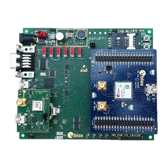
EVK-LEXI-R520 - User guide Introduction The EVK-LEXI-R520 kit is a powerful and easy-to-use tool that simplifies the evaluation of the u-blox LEXI-R520 multi-band LTE-M / NB-IoT cellular modules. As shown in Figure 1, the EVK-LEXI-R520 evaluation kit is formed by three boards: •... -
Page 5: Board Quick Start
Figure 2: SIM and antenna set up 1. Insert a SIM card into J300, the SIM card holder. 2. Connect the cellular antenna provided with the EVK-LEXI-R520 evaluation kit box to J106, the cellular antenna SMA connector. 3. If positioning functionality is required: a. -
Page 6: Power Supply
EVK-LEXI-R520 - User guide 2.1.2 Power supply J403 J402 DL401 DL401 J400 SW400 J300 J404 DL400 DL400 DL405 J103 (J102 on bottom side) J500 J108 DS501 DS500 J501 J106 DL501 DL403 J105 DS100 J103 J107 J102 J104 (J101 on bottom side) -
Page 7: Local Connectivity
EVK-LEXI-R520 - User guide 2.1.3 Local connectivity J403 J402 DL401 SW400 J400 J300 SW401 SW403 J404 DL400 DL405 J103 DL405 DL404 J500 DS501 DS500 DL501 J501 J106 DL501 DL403 DL403 J105 DS100 J103 J107 J102 J104 J406 J405 Figure 4: Local connectivity set up... -
Page 8: Switch Off The Board
EVK-LEXI-R520 - User guide Run an AT terminal application (such as the u-blox m-center tool) selecting the AT port, with these settings: Data rate Data bits Parity Stop bits Flow control 115200 bit/s See appendix for how to download, configure and use the u-blox m-center AT terminal for Windows. -
Page 9: Register To Network
EVK-LEXI-R520 - User guide Register to network 3.1 Enabling error result codes Command sent by DTE (user) DCE response (module) Description AT+CMEE=2 Enable the cellular module to report verbose error result codes. 3.2 PIN code insertion (when required) Command sent by DTE (user) -
Page 10: Setting Up Data Connection On Windows
This section describes how to set up a cellular packet data connection on Windows 10 using the operating system’s TCP/IP stack and EVK-LEXI-R520. This is also referred to as a dial-up connection. 4.1 Install a new modem from the control panel 1. - Page 11 EVK-LEXI-R520 - User guide 3. Select Standard 33600 bps Modem. Click Next. 4. Select COM port for data communication and click Next. The modem will be installed on this COM port. 5. Click Finish to complete the installation. 6. Now the new modem is visible in Control Panel, under Phone and Modem >...
-
Page 12: Configuring A New Connection
A name for the connection, e.g., “EVK-LEXI-R520 dial-up” The packet data connection is now ready with EVK-LEXI-R520. Click Connect, then start a browser to check internet connectivity. Consult the cellular network operator for username and password. Usually, they can remain empty. -
Page 13: Evk-Lexi-R520 Hardware
(J103 and J104) provided on the top layer of the cellular adapter board. The lower board (EVB-WL3) is also designed to be used with other u-blox cellular adapter boards. It contains additional switches, jumpers, connectors, LEDs and parts that may be only partially described in this document, because they are intended for use only with other u-blox cellular modules. -
Page 14: Switches, Jumpers And Buttons
3-pin header jumper to route and make accessible GNSS UART Tx over J104 ADP-GNSS the USB connector on the ADP-GNSS or to use it as Tx data ready for the cellular module Table 2: EVK-LEXI-R520 switches, jumpers and buttons description UBXDOC-686885345-1791 - R02 EVK-LEXI-R520 hardware Page 14 of 23 C1-Public... -
Page 15: Leds
ADP-GNSS GNSS time pulse MAX-M10S GNSS time pulse DS121 ADP-GNSS Cellular / GNSS I2C Cellular / GNSS module communication over the I2C interface DS107 ADP-GNSS Table 3: EVK-LEXI-R520 LEDs description UBXDOC-686885345-1791 - R02 EVK-LEXI-R520 hardware Page 15 of 23 C1-Public... -
Page 16: Connectors
J102 ADP-GNSS USB interface Table 4: EVK-LEXI-R520 connectors description ⚠ In the unlikely event of a failure in the internal protection circuitry, there is a risk of an explosion when charging a fully or a partially discharged battery. Replace the battery when it no longer has sufficient charge for unit operation. -
Page 17: Evk-Lexi-R520 Pin Out
EVK-LEXI-R520 - User guide 5.5 EVK-LEXI-R520 pin out Table 5 lists the interfaces of the LEXI-R520 modules, as routed up to the 42-pin dual-in-line board-to-board connectors (J103 and J104) available on the ADP-LEXI-R520 adapter board of the evaluation kit. LEXI-R520 module... - Page 18 EVK-LEXI-R520 - User guide Dual-in-line board-to-board connector J104 Dual-in-line board-to-board connector J103 Signal name Pin no. Pin no. Signal name Signal name Pin no. Pin no. Signal name Not connected Not connected Not connected Not connected ANT_DET ANT_ON Not connected...
-
Page 19: Current Consumption Measurement
EVK-LEXI-R520 - User guide 5.6 Current consumption measurement To measure the current consumption of LEXI-R520 modules, remove the jumper socket from the cellular VCC supply jumper J108 on the ADP-LEXI-R520 board, as shown in Figure J403 J402 DL401 SW400 J400... -
Page 20: Appendix
1. Follow the board setup instructions in section to provide all the required connections and switching on the cellular module. 2. Run the u-blox m-center tool: after the m-center start-up, the Home page appears, as shown in Figure Figure 9: m-center Home page 3. - Page 21 AT command terminal is now ready for communication with the EVK-LEXI-R520. Figure 10: AT terminal window For more information on using the u-blox m-center, press the F1 key to open the m-center help window on the computer. For the complete list of the AT commands supported by the modules and their syntax, see the AT commands manual [1].
-
Page 22: B Glossary
EVK-LEXI-R520 - User guide B Glossary Abbreviation Definition Alternating current Analog to Digital Converter Adapter Board Access Point Name AT Command Interpreter Software Subsystem, or attention A-GPS Assisted Global Positioning System Board-To-Board Clear To Send Direct current Data Carrier Detect... -
Page 23: C Conformity Notice
(petrol stations, refineries…). Any changes or modification made to this equipment will void its compliance to the safety requirements. Maintenance, inspections and/or repairs of the EVK-LEXI-R520 shall be performed by u-blox AG. Related documentation...
Need help?
Do you have a question about the EVK-LEXI-R520 and is the answer not in the manual?
Questions and answers