Table of Contents
Advertisement
C099-F9P
Application Board (Rev. B)
User Guide
Abstract
The C099-F9P board enables customers to evaluate RTK operation with the ZED-F9P high precision
GNSS receiver. The board provides short-range wireless connection via Bluetooth® or Wi-Fi for
receiving correction data and logging via wireless connectivity.
www.u-blox.com
UBX-18055649 - R02
Advertisement
Table of Contents

Related Manuals for u-blox C099-F9P


Summary of Contents for u-blox C099-F9P
- Page 1 Application Board (Rev. B) User Guide Abstract The C099-F9P board enables customers to evaluate RTK operation with the ZED-F9P high precision GNSS receiver. The board provides short-range wireless connection via Bluetooth® or Wi-Fi for receiving correction data and logging via wireless connectivity.
-
Page 2: Document Information
The information contained herein is provided “as is” and u-blox assumes no liability for its use. No warranty, either express or implied, is given, including but not limited to, with respect to the accuracy, correctness, reliability and fitness for a particular purpose of the information. -
Page 3: Table Of Contents
Rover operation using NTRIP ......................20 5.1 PC hosting via u-center ..........................20 5.2 Mobile hosting ............................21 5.3 Pairing the host with the C099-F9P ...................... 21 Reference station and rover pairing ..................... 22 6.1 Wi-Fi connection between two C099-F9P boards ................22 Configuring a C099-F9P rover for Wi-Fi operation .............. - Page 4 C099-F9P - User Guide E.2.1 Patch antenna element specification ..................37 E.2.2 LNA electrical specification ......................38 E.2.3 Overall performance ......................... 38 Mechanical board dimensions ......................39 C099-F9P schematics ........................40 Related documents ........................... 47 Revision history ............................47 Contact ................................48...
-
Page 5: Introduction
RTCM corrections while sending back logged data using u-center evaluation software [3]. There is an option to use two C099-F9P boards together, one as a reference station and the other as a rover, sending corrections over a Wi-Fi connection. -
Page 6: Additional Sources Of Information
ZED-F9P Interface Description, Doc. No. UBX-18010854 • Download u-center: https://www.u-blox.com/en/product/u-center-windows and the u-center User Guide: https://www.u-blox.com/sites/default/files/u-center_UserGuide_(UBX-13005250).pdf • Download the u-blox GNSS Sensor and VCP Device Driver guide: https://www.u-blox.com/sites/default/files/products/documents/u-blox-GNSS-Sensor-and-VCP- Device-Driver_UserGuide_(UBX-15022397).pdf • Download s-center: https://www.u-blox.com/en/product/s-center UBX-18055649 - R02 Introduction Page 6 of 48... -
Page 7: C099-F9P Quick Start
RTK corrections can be applied using a u-center built-in NTRIP client. To use the C099-F9P board with a correction service follow these next steps: •... - Page 8 C099-F9P - User Guide • Click OK to close the dialog and connect to the service • In the Data View of u-center, the Fix Mode should change from “3D” to “3D/DGNSS” when RTCM corrections are received. The RTK LED will blink in green color.
-
Page 9: C099-F9P Description
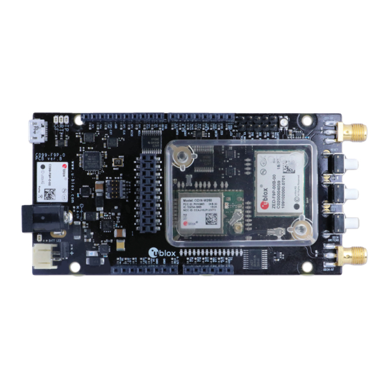
C099-F9P - User Guide C099-F9P description 3.1 Component overview The C099-F9P houses the ZED-F9P RTK high precision positioning module plus an ODIN-W2 module for wireless short-range communications. An FTDI component provides dedicated COM port connections with the ZED-F9P and ODIN-W2 via USB. - Page 10 C099-F9P - User Guide GNSS antenna connector Wi-Fi/BT antenna connector ZED-F9P Multi band GNSS RTK module ODIN-W2 Multi-radio module J2, J3, J8, J9 Arduino Uno connectors DC power jack Battery connector USB (ZED-F9P USB and UART, ODIN-W2 UART ports) Figure 5: Main components and USB ports...
-
Page 11: Zed-F9P Status Leds
C099-F9P - User Guide ODIN-W2 Switch 0 interrupt button ZED-F9P Safeboot button ZED-F9P and ODIN-W2 reset button ODIN-W2 activity LED ODIN-W2 Safeboot pins GNSS LEDs: TP, RTK, GeoFence Battery charger LED Figure 6: Switches and LEDs ☞ The MicroSD card slot is not used in this version of the board. The ODIN-W2 Switch 0 interrupt is not required for normal customer use. -
Page 12: Odin-W2 Activity Led
Data mode, Command mode, EDM CONNECTED Blue Table 1: LED activity states and colors ODIN-W2 activity LED Figure 8: ODIN-W2 Activity LED position on C099-F9P board On data activity, the active LED flashes. UBX-18055649 - R02 C099-F9P description Page 12 of 48... -
Page 13: Using The C099-F9P
C099-F9P - User Guide Using the C099-F9P The ZED-F9P is shipped with the latest firmware and the ODIN-W2 is pre-configured as a Bluetooth serial device. Information on updating either module’s firmware is provided in section 7, if required. 4.1 Powering the board The board can be powered from a variety of sources: •... -
Page 14: Gnss Rf Input
4.2 GNSS RF input The C099-F9P board should be used with the antenna supplied with the kit. If another active antenna is used, be aware that the RF input has a bias output designed to supply 3.3V DC with a 70 mA maximum current load. -
Page 15: Ftdi Usb Bridge
Windows installations a driver will be loaded via Windows update. In this case the device will be identified as a u-blox GNSS device in the Device Manager window. Open u-center (V18.06 or later), select the ZED-F9P serial port, and set the baud rate to 460800 to match the ZED-F9P default UART setting. -
Page 16: Bluetooth Serial Com Port Connection
SMA connector “ODIN-RF” to ensure correct operation of the wireless functions. The C099-F9P board is delivered with the ODIN-W2 pre-configured for connecting the ZED-F9P as a Bluetooth serial device. On a PC, go to the Bluetooth setup and add the ODIN-W2 module as a device, identified as “ODIN-W2-XXXX”. - Page 17 Jumper position “3OE” Figure 19: C099 rover jumper position For information, Figure 20 below shows the C099-F9P logical connections for serial interfaces with the “OE3” jumper set as required to connect the ODIN-W2 and ZED-F9P serial ports. UBX-18055649 - R02...
-
Page 18: Windows Os Issues With Bluetooth Spp
C099-F9P - User Guide Figure 20: Schematic showing serial interface connection with jumper OE3 setting Windows OS issues with Bluetooth SPP There are some known issues with the Windows Bluetooth Serial Port Profile (SPP) implementation for Windows 7-10. Symptoms include the Bluetooth Virtual COM port not installing or applications not connecting to the Bluetooth Virtual COM port. -
Page 19: Arduino Uno Header Connections
Arduino R3/Uno - see Figure 23 below. All the pin functions besides power are 3.3V compliant. J9, Arduino D J3, Arduino B J8, Arduino C J2, Arduino A Figure 22: C099-F9P Arduino connectors Figure 23 C099-F9P Arduino R3 connections UBX-18055649 - R02 Using the C099-F9P Page 19 of 48... -
Page 20: Rover Operation Using Ntrip
RTK Virtual Reference Service (VRS). Suitable hosts are a PC with internet access and/or an Android cellular phone with mobile data capability. The host runs an NTRIP client and streams RTCM corrections to the C099-F9P. 5.1 PC hosting via u-center The u-center application includes an NTRIP client for PC hosting. -
Page 21: Mobile Hosting
☞ https://play.google.com/store/apps/details?id=com.lefebure.ntripclient Figure 27: Lefebure Android NTRIP client 5.3 Pairing the host with the C099-F9P For both options the user needs to pair the host (PC or mobile) with the C099 ODIN-W2 wireless module. Once paired the user can then attach the host application to the C099 to send and receive data. -
Page 22: Reference Station And Rover Pairing
This section is provided for users with two C099 boards and provides configuration information when setting up a C099-F9P as a reference station to provide local RTCM corrections for a C099 rover. This connection uses Wi-Fi connectivity to maximize range for untethered operation. - Page 23 C099-F9P - User Guide Figure 29: s-center connection setting window • Select the COM port installed for the ODIN-W2. • Set the baud rate to 460800 baud. • Ensure there is no hardware flow control enabled. • Click on the FTDI USB Latency Timer Update button.
- Page 24 Click the AT mode button to ensure it is responding correctly. You will see it respond with AT commands if communication is ok. Figure 33: Clicking AT Mode button Download the u-blox configuration file for the rover Wi-Fi link. Use the “Rover ODIN-W2 Access Point UDP Server.txt” file listed in Appendix C. Select “File > Download Configuration”.
-
Page 25: Configuring A C099 Reference Station For Wi-Fi Operation
Select the “Rover ODIN-W2 Access Point UDP Server.txt” file and click Open. Figure 35: Selecting File “Rover ODIN-W2 Access Point UDP Server.txt” Disconnect s-center from the ODIN-W2 port and toggle the C099-F9P off and on again to ensure it will be using the new configurations as default. - Page 26 Connect the GNSS antenna, ensuring use with the supplied ground plane and place in good GNSS visibility conditions. A Wi-Fi connection is established between reference and rover boards when the rover C099-F9P is powered up. The ODIN-W2 activity LED is set blue when the base and rover have connected and flashes when data transfer is occurring.
-
Page 27: Firmware Updates
C099-F9P - User Guide Firmware updates This section shows how to update the GNSS and Wi-Fi/Bluetooth modules’ firmware if required. The board is delivered with the latest versions of firmware running on the ZED-F9P and ODIN-W2 modules. However, newer versions may become available during the lifetime of the product. - Page 28 C099-F9P - User Guide Figure 40: Selecting u-center Firmware image folder At the top is the Firmware image file selection window. Click on the button to the right of the window. This allows you to select the folder and file. Select the new firmware image bin file.
- Page 29 C099-F9P - User Guide Figure 43: Click GO for firmware update The firmware update progress indication is shown adjacent to the input window. Figure 44: Programming progress and completion message When programming is complete, the module will start up in a default configuration in which the ZED- F9P serial port is set to 38400 baud.
-
Page 30: Odin-W2 Firmware Update
Figure 46: Saving ZED-F9P UART1 baud rate configuration to Flash 7.2 ODIN-W2 firmware update The C099-F9P is shipped with ODIN-W2 FW5.0 standard connectivity firmware. If there is a need to update the firmware, then users should adopt the following process. - Page 31 C099-F9P - User Guide • Select the COM port installed for the ODIN-W2. • Set the baud rate to 460800 baud. • Ensure there is no hardware flow control enabled. • Click on the FTDI USB Latency Timer Update button.
- Page 32 C099-F9P - User Guide Figure 50: s-center select ODIN-W2 firmware, Normal mode, COM port, baud rate Select the ODIN-W2 Firmware folder and ODIN-W26X_Firmware bin file. Do not select a Boot image. Ensure the set COM port and baud rate is correct.
- Page 33 The ODIN-W2 UART will now be set to 460800 baud in Data default mode. It will be ready for use again. Disconnect s-center from the ODIN-W2 port and power the C099-F9P off and on to ensure it will be using the new configurations as default.
-
Page 34: Appendix
Coordinated Universal Time Virtual Com Port Table 2: Explanation of the abbreviations and terms used B u-blox ODIN-W2 BT Rover.txt Copy all the text below this line and place it in a text file named “u-blox ODIN-W2 BT Rover.txt”. AT+UBTLN="ODIN-W2-xxxx" AT+UBTLC=000000 AT+UBTCM=2... -
Page 35: C Rover Odin-W2 Access Point Udp Server.txt
C099-F9P - User Guide AT+UBTLECFG=1,1600 AT+UBTLECFG=2,2000 AT+UBTLECFG=3,7 AT+UBTLECFG=4,24 AT+UBTLECFG=5,40 AT+UBTLECFG=6,0 AT+UBTLECFG=7,2000 AT+UBTLECFG=8,5000 AT+UBTLECFG=9,48 AT+UBTLECFG=10,48 AT+UBTLECFG=11,24 AT+UBTLECFG=12,40 AT+UBTLECFG=13,0 AT+UBTLECFG=14,2000 AT+UBTLECFG=15,5000 AT+UBTLECFG=16,48 AT+UBTLECFG=17,48 AT+UBTLECFG=18,24 AT+UBTLECFG=19,40 AT+UBTLECFG=20,0 AT+UBTLECFG=21,2000 AT+UBTLECFG=22,5000 AT+UBTLECFG=23,48 AT+UBTLECFG=24,48 AT+UBTLECFG=25,0 AT+UMSM=1 AT+UMRS=460800,2,8,1,1,1 AT&W AT+CPWROFF C Rover ODIN-W2 Access Point UDP Server.txt Copy all the text below this line and put it in a text file named “Rover ODIN-W2 Access Point UDP... -
Page 36: D Reference Station Odin-W2 Udp Client.txt
FCC, IC, RED, MIC, NCC, KCC*, ANATEL, and ICASA Table 3: Wi-Fi/Bluetooth antenna ☞ The variant included in the C099-F9P kit is with SMA connector and has to be mounted on the corresponding antenna connector of the C099-F9P board if you wish to use Wi-Fi or Bluetooth connectivity. -
Page 37: Multi-Band Gnss Antenna Specification
C099-F9P - User Guide E.2 Multi-band GNSS antenna specification This section details the u-blox multi-band GNSS antenna specification and performance on the required ground plane. Figure 55: u-blox dual band GNSS antenna E.2.1 Patch antenna element specification Figure 56: Patch elements specification... -
Page 38: Lna Electrical Specification
C099-F9P - User Guide E.2.2 LNA electrical specification Figure 57: LNA specification E.2.3 Overall performance Figure 58: u-blox multi-band GNSS antenna performance UBX-18055649 - R02 Appendix Page 38 of 48... -
Page 39: F Mechanical Board Dimensions
C099-F9P - User Guide F Mechanical board dimensions Figure 59: C099-F9P rev. B dimensions UBX-18055649 - R02 Appendix Page 39 of 48... -
Page 40: G C099-F9P Schematics
C099-F9P - User Guide G C099-F9P schematics The following pages show the complete schematic for the C099-F9P evaluation board. UBX-18055649 - R02 Appendix Page 40 of 48... - Page 41 C099-F9P - User Guide UBX-18055649 - R02 Appendix Page 41 of 48...
- Page 42 C099-F9P - User Guide UBX-18055649 - R02 Appendix Page 42 of 48...
- Page 43 C099-F9P - User Guide UBX-18055649 - R02 Appendix Page 43 of 48...
- Page 44 C099-F9P - User Guide UBX-18055649 - R02 Appendix Page 44 of 48...
- Page 45 C099-F9P - User Guide UBX-18055649 - R02 Appendix Page 45 of 48...
- Page 46 C099-F9P - User Guide UBX-18055649 - R02 Appendix Page 46 of 48...
-
Page 47: Related Documents
ZED-F9P Interface Description, Doc. No. UBX-18010854 u-center User Guide, Doc. No. UBX-13005250 ZED-F9P Integration Manual, Doc No. UBX-18010802 ☞ For regular updates to u-blox documentation and to receive product change notifications, register on our homepage (www.u-blox.com). Revision history Revision Date... -
Page 48: Contact
C099-F9P - User Guide Contact For complete contact information, visit us at www.u-blox.com. u-blox Offices North, Central and South America Headquarters Asia, Australia, Pacific Europe, Middle East, Africa u-blox America, Inc. u-blox Singapore Pte. Ltd. u-blox AG Phone: +1 703 483 3180...
Need help?
Do you have a question about the C099-F9P and is the answer not in the manual?
Questions and answers