Table of Contents
Advertisement
Quick Links
C099-F9P
Application board (rev. E), ODIN-W2 u-connectXpress
SW
User guide
Abstract
The C099-F9P board enables customers to evaluate RTK operation with the ZED-F9P high precision
GNSS receiver. The board provides short-range wireless connection via Bluetooth® or Wi-Fi for
receiving correction data and logging via wireless connectivity.
www.u-blox.com
UBX-18055649 – R07
- User guide
Advertisement
Table of Contents

Subscribe to Our Youtube Channel
Related Manuals for u-blox C099-F9P


Summary of Contents for u-blox C099-F9P
- Page 1 Application board (rev. E), ODIN-W2 u-connectXpress User guide Abstract The C099-F9P board enables customers to evaluate RTK operation with the ZED-F9P high precision GNSS receiver. The board provides short-range wireless connection via Bluetooth® or Wi-Fi for receiving correction data and logging via wireless connectivity.
-
Page 2: Document Information
The information contained herein is provided “as is” and u-blox assumes no liability for its use. No warranty, either express or implied, is given, including but not limited to, with respect to the accuracy, correctness, reliability and fitness for a particular purpose of the information. -
Page 3: Table Of Contents
Reference station and rover pairing ..................... 22 6.1 Wi-Fi connection between two C099-F9P boards ................22 Configuring a C099-F9P rover for Wi-Fi operation ..............22 Configuring a C099-F9P reference station (Base) for Wi-Fi operation .........25 ZED-F9P reference station (Base) and rover configuration ............26 Firmware update ..........................29 7.1 ZED-F9P firmware update ........................29... - Page 4 C099-F9P - User guide F9P Base config C99.txt ........................40 F9P Rover config C99.txt ......................... 41 H C099-F9P antenna specification ....................41 H.1 Wi-Fi/Bluetooth antenna specification ..................41 Mechanical board dimensions ......................42 C099-F9P schematics ........................43 Related documents ........................... 49 Revision history ............................
-
Page 5: Introduction
C099-F9P - User guide Introduction The C099-F9P board is a convenient tool that allows customers to become familiar with the u-blox ZED-F9P high precision GNSS module. The board provides facilities for evaluating the product and demonstrating its key features. The C099-F9P application board offers: ... -
Page 6: Package Contents
C099-F9P - User guide 1.1 Package contents The delivered package contains: C099-F9P board (rev. E) u-blox ANN-MB-00 multi-band GNSS antenna and ground plane Wi-Fi/Bluetooth antenna USB interconnect cable Quick start guide USB-to-DC plug adapter cable Figure 1: C099-F9P board and antennas 1.2 Additional sources of information... -
Page 7: C099-F9P Quick Start
Device Manager. Set the baud rate to 460800 baud. See section 4.3.1 for detailed instructions. The time pulse LED on the C099-F9P board will blink in blue. Figure 3 below shows a typical u-center view with active satellite signal levels. - Page 8 C099-F9P - User guide Eventually, the status will change to 3D/DGNSS/FIXED and the RTK LED will show a steady green light. Figure 3: u-center showing a view of the ZED-F9P default operation UBX-18055649 - R07 C099-F9P quick start Page 8 of 50...
-
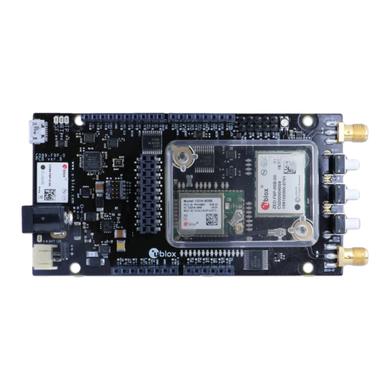
Page 9: C099-F9P Description
C099-F9P description 3.1 Component overview The C099-F9P houses the ZED-F9P RTK high precision positioning module and an ODIN-W2 module for wireless short-range communications. An FTDI component provides dedicated COM port connections with the ZED-F9P and ODIN-W2 via a USB connector. - Page 10 C099-F9P - User guide GNSS antenna connector Wi-Fi/BT antenna connector ZED-F9P multi band GNSS RTK module ODIN-W2 multi-radio module J2, J3, J8, J9 Arduino Uno connectors DC power jack Battery connector USB (ZED-F9P USB and UART, ODIN-W2 UART ports) Figure 5: Main components and USB ports...
-
Page 11: Zed-F9P Status Leds
C099-F9P - User guide ZED-F9P and ODIN-W2 reset button ZED-F9P safeboot button ODIN-W2 switch 0 interrupt button ODIN-W2 activity LED ODIN-W2 safeboot pins GNSS LEDs: TP, RTK, Geofence Battery charger LED Battery incorrect polarity indicator Figure 6: Switches and LEDs ☞... -
Page 12: Odin-W2 Activity Led
CONNECTED Blue Table 1: ODIN-W2 u-connectXpress software LED activity states and colors ODIN-W2 activity LED Figure 8: ODIN-W2 Activity LED position on C099-F9P board On data activity, the active LED flashes. UBX-18055649 - R07 C099-F9P description Page 12 of 50... -
Page 13: Using The C099-F9P
C099-F9P - User guide Using the C099-F9P The C099-F9P is shipped with the latest HPG firmware for the ZED-F9P GNSS module. Information on updating either module’s firmware is provided in section 7 Firmware update, if required. 4.1 Powering the board The board can be powered from a variety of sources: ... -
Page 14: Non-Wireless Operation
4.2 GNSS RF input The C099-F9P board should be used with the antenna supplied with the kit. If another active antenna is used, be aware that the RF input has a bias output designed to supply 3.3 V DC with a 70 mA maximum current load. -
Page 15: User Interfaces
Figure 13: The supplied GNSS multi-band antenna 4.3 User interfaces The C099-F9P has a number of fixed connection options besides the wireless modes. There is also an additional Arduino R3 / Uno interface for external host connection. The USB connector on the board provides connection via an on-board hub providing: ... -
Page 16: Bluetooth Serial Com Port Connection
SMA connector “ODIN-RF” to ensure correct operation of the wireless functions. Create the u-blox configuration file for the rover BT link. Use the “u-blox ODIN-W2 BT Rover.txt” file listed in Appendix D. You can also download the file from Github: https://github.com/u-... - Page 17 C099-F9P - User guide Figure 16: Windows 7 Add a device window shows ODIN-W2 Figure 17: Click on the ODIN-W2 and select Next You can locate the device by examining the Bluetooth connections under the Ports tab in the Windows Device Manager.
- Page 18 Jumper position “3OE” Figure 19: C099-F9P rover jumper position For information, Figure 20 below shows the C099-F9P logical connections for serial interfaces with the “OE3” jumper set as required to connect the ODIN-W2 and ZED-F9P serial ports. Figure 20: Schematic showing serial interface connection with jumper OE3 setting...
- Page 19 C099-F9P - User guide 4.3.2.1 Windows OS issues with Bluetooth SPP There are some known issues with the Windows Bluetooth Serial Port Profile (SPP) implementation for Windows 7-10. Symptoms include the Bluetooth Virtual COM port not installing or applications not connecting to the Bluetooth Virtual COM port. In other cases Windows might crash or become un- responsive.
-
Page 20: Rover Operation Using Ntrip
A suitable host is a PC with internet access. A host runs an NTRIP client and streams RTCM corrections to the C099-F9P through a UART or Bluetooth connection. Messages transmitted through a Bluetooth or Wi-Fi link are forwarded to I2C bus and vice versa. The user is advised to enable desired messages in both UART and I2C interfaces in ZED-F9P. -
Page 21: Mobile Hosting
Figure 25: Lefebure Android NTRIP client 5.3 Pairing the host with the C099-F9P For both options the user needs to pair the host (PC or mobile) with the C099-F9P ODIN-W2 wireless module. Once paired the user can then attach the host application to the C099-F9P to send and receive data. -
Page 22: Reference Station And Rover Pairing
This section is provided for users with two C099-F9P boards and provides configuration information when setting up a C099-F9P as a reference station to provide local RTCM corrections for a C099-F9P rover. This connection uses Wi-Fi connectivity to maximize range for untethered operation. - Page 23 Click on the “FTDI USB Latency Timer” Update button. Click Open Port. If the C099-F9P is powered, the ODIN-W2 responds with AT commands. Figure 28: s-center connected to ODIN-W2 UBX-18055649 - R07 Reference station and rover pairing Page 23 of 50...
- Page 24 OK. Figure 31: Clicking AT Mode button Download the u-blox configuration file for the rover Wi-Fi link. Use the “Rover ODIN-W2 Access Point UDP Server.txt” file listed in Appendix D. You can also download the file from Github: https://github.com/u-blox/ublox-C099_F9P-uCS/tree/master/odin-w2...
-
Page 25: Configuring A C099-F9P Reference Station (Base) For Wi-Fi Operation
Select the “Rover ODIN-W2 Access Point UDP Server.txt” file and click Open. Figure 33: Selecting file “Rover ODIN-W2 Access Point UDP Server.txt” Disconnect s-center from the ODIN-W2 port and toggle the C099-F9P off and on again to ensure it will be using the new configurations as default. -
Page 26: Zed-F9P Reference Station (Base) And Rover Configuration
C099-F9P - User guide ZED-F9P reference station (Base) and rover configuration With the latest version u-center, connect to the C099-F9P using the dedicated ZED-F9P USB connection. See section “Required configuration of the base and rover” in the ZED-F9P Integration Manual [2] for details on configuring the required RTCM3 messages and setting the ZED-F9P as a reference station. - Page 27 Load and Send the “F9P Rover config C99.txt” file as shown in the previous section. Both units will now be ready to operate. You would have previously downloaded it from the u-blox GITHUB repository, or copied the contents of Appendix F to a .txt file.
- Page 28 C099-F9P - User guide A Wi-Fi connection is established between reference and rover boards when the rover C099-F9P is powered up. The ODIN-W2 activity LED is set blue when the base and rover have connected and flashes when data transfer is occurring. Look for acquisition activity shown in u-center to confirm the rover is operating correctly.
-
Page 29: Firmware Update
7.1 ZED-F9P firmware update This section shows how to update the firmware and re-enable the configuration settings required for the C099-F9P. The user has two possible serial communication channels to update ZED-F9P: UART1 and USB2.0 ports. To update the ZED-F9P, connect to u-center via USB to the COM port identified as the ZED-F9P and poll MON-VER to view the installed firmware: see Figure 14 for the Device Manager COM port view. - Page 30 C099-F9P - User guide Figure 42: Selecting u-center Firmware image folder At the top is the Firmware image file selection window. Click on the button to the right of the window. This allows you to select the folder and file. Select the new firmware image bin file.
-
Page 31: Odin-W2 Firmware Update
Figure 46: Setting ZED-F9P UART1 back to 460800 baud and saving it to flash memory 7.2 ODIN-W2 firmware update Users have a choice of running two distinct firmware variants in ODIN-W2. By factory default the ODIN-W2 on a C099-F9P runs a dedicated Mbed application firmware. UBX-18055649 - R07 Firmware update... -
Page 32: Mbed Os 3 Application Firmware
Prior to firmware upload, the ODIN-W2 must be started in safeboot mode. Proceed by placing a safeboot jumper and reboot C099-F9P. Location of the safeboot pin header and the reset button is depicted in Figure 6. To confirm the ODIN-W2 started in safeboot mode the ODIN-W2 activity LED remains off. - Page 33 Prior to bootloader upload, the ODIN-W2 must be restarted in safe boot mode. Proceed by placing a safe boot jumper and reboot the C099-F9P. The location of the safe boot pin header and the reset button is depicted in Figure 6: Switches and LEDs.
- Page 34 C099-F9P - User guide Execute the following command set sequentially: AT+UMRS=460800,2,8,1,1,0 AT&W AT+CPWROFF Finally, adjust s-center baud rate to match 460800 by closing and opening the UART port. Figure 50: Set baud rate Click the AT Mode button to ensure it is responding correctly. You will see it respond with AT commands if communication is OK.
- Page 35 The ODIN-W2 UART will now be set to 460800 baud in Data default mode. It will be ready for use again. Disconnect s-center from the ODIN-W2 port and power the C099-F9P off and on to ensure it will be using the new configurations as default.
-
Page 36: Arduino Header Connections
Arduino R3/Uno; see Figure 55 below. All the pin functions besides power are 3.3 V compliant. J9, Arduino D J3, Arduino B J8, Arduino C J2, Arduino A Figure 54: C099-F9P Arduino connectors Figure 55 C099-F9P Arduino R3 connections UBX-18055649 - R07 Arduino header connections Page 36 of 50... -
Page 37: Appendix
Table 2: Explanation of the abbreviations and terms used B Resources Applicable configuration files are available in u-blox Github: https://github.com/u-blox/ublox-C099_F9P-uCS C u-blox ODIN-W2 BT Rover.txt Copy all the text below this line into a text file named “u-blox ODIN-W2 BT Rover.txt”. AT+UBTLN="ODIN-W2-xxxx" AT+UBTLC=000000 AT+UBTCM=2 AT+UBTDM=3... - Page 38 C099-F9P - User guide ATE1 AT+UBTCFG=1,1 AT+UBTCFG=2,1 AT+UBTCFG=3,56602 AT+UBTCFG=4,127 AT+UBTCFG=5,0 AT+UBTCFG=6,0 AT+UBTCFG=7,2000 AT+UBTCFG=8,0 AT+UBTCFG=9,0 AT+UBTLECFG=1,1600 AT+UBTLECFG=2,2000 AT+UBTLECFG=3,7 AT+UBTLECFG=4,24 AT+UBTLECFG=5,40 AT+UBTLECFG=6,0 AT+UBTLECFG=7,2000 AT+UBTLECFG=8,5000 AT+UBTLECFG=9,48 AT+UBTLECFG=10,48 AT+UBTLECFG=11,24 AT+UBTLECFG=12,40 AT+UBTLECFG=13,0 AT+UBTLECFG=14,2000 AT+UBTLECFG=15,5000 AT+UBTLECFG=16,48 AT+UBTLECFG=17,48 AT+UBTLECFG=18,24 AT+UBTLECFG=19,40 AT+UBTLECFG=20,0 AT+UBTLECFG=21,2000 AT+UBTLECFG=22,5000 AT+UBTLECFG=23,48 AT+UBTLECFG=24,48 AT+UBTLECFG=25,0 AT+UMSM=1 AT+UMRS=460800,2,8,1,1,1 AT&W...
-
Page 39: D Rover Odin-W2 Access Point Udp Server.txt
C099-F9P - User guide D Rover ODIN-W2 Access Point UDP Server.txt Copy all the text below this line into a text file named “Rover ODIN-W2 Access Point UDP Server .txt”. AT+UWAPCA=0,4 AT+UWAPC=0,0,1 AT+UWAPC=0,2,UBXWifi AT+UWAPC=0,4,1 AT+UWAPC=0,5,1,1 AT+UWAPC=0,100,1 AT+UWAPC=0,101,192.168.0.10 AT+UWAPC=0,102,255.255.0.0 AT+UWAPC=0,103,192.168.0.1 AT+UWAPC=0,104,0.0.0.0 AT+UWAPC=0,105,0.0.0.0... -
Page 40: F F9P Base Config C99.Txt
C099-F9P - User guide F F9P Base config C99.txt Copy all the text below this line into a text file named “F9P Base config C99.txt. # Config changes format version 1.0 # created by u-center version 18.11 at 11:37:53 on Tuesday, 08 Jan 2019... -
Page 41: G F9P Rover Config C99.Txt
FCC, IC, RED, MIC, NCC, KCC*, ANATEL, and ICASA Table 3: Wi-Fi/Bluetooth antenna ☞ The variant included in the C099-F9P kit is with SMA connector and has to be mounted on the corresponding antenna connector of the C099-F9P board if you wish to use Wi-Fi or Bluetooth connectivity. -
Page 42: I Mechanical Board Dimensions
C099-F9P - User guide I Mechanical board dimensions Figure 56: C099-F9P rev. E dimensions UBX-18055649 - R07 Appendix Page 42 of 50... -
Page 43: J C099-F9P Schematics
C099-F9P - User guide J C099-F9P schematics The following pages show the complete schematic for the C099-F9P evaluation board. UBX-18055649 - R07 Appendix Page 43 of 50... - Page 44 C099-F9P - User guide UBX-18055649 - R07 Appendix Page 44 of 50...
- Page 45 C099-F9P - User guide UBX-18055649 - R07 Appendix Page 45 of 50...
- Page 46 C099-F9P - User guide UBX-18055649 - R07 Appendix Page 46 of 50...
- Page 47 C099-F9P - User guide UBX-18055649 - R07 Appendix Page 47 of 50...
- Page 48 C099-F9P - User guide UBX-18055649 - R07 Appendix Page 48 of 50...
-
Page 49: Related Documents
Short Range Modules AT Commands Manual, doc no. UBX-14044127 s-center: https://www.u-blox.com/en/product/s-center ANN-MB series multi-band GNSS antennas Data sheet, doc.no. UBX-18049862 ☞ For regular updates to u-blox documentation and to receive product change notifications, register on our homepage (www.u-blox.com). Revision history Revision Date... -
Page 50: Contact
C099-F9P - User guide Contact For complete contact information, visit us at www.u-blox.com. u-blox Offices North, Central and South America Headquarters Asia, Australia, Pacific Europe, Middle East, Africa u-blox America, Inc. u-blox Singapore Pte. Ltd. u-blox AG Phone: +1 703 483 3180...
Need help?
Do you have a question about the C099-F9P and is the answer not in the manual?
Questions and answers