
Subscribe to Our Youtube Channel
Related Manuals for u-blox XPLR-HPG-1


Summary of Contents for u-blox XPLR-HPG-1
- Page 1 XPLR-HPG-1 High Precision GNSS evaluation platform User guide UBX-23000692 - R01 C1-Public www.u-blox.com...
-
Page 2: Document Information
Disclosure to third parties is permitted for clearly public documents only. The information contained herein is provided “as is” and u-blox assumes no liability for its use. No warranty, either express or implied, is given, including but not limited to, with respect to the accuracy, correctness, reliability, and fitness for a particular purpose of the information. -
Page 3: Table Of Contents
XPLR-HPG-1 - User guide Contents Document information ..........................2 Contents ................................3 Product description ..........................5 1.1 Overview ................................ 5 1.2 Module integration ............................. 7 1.3 Kit includes ..............................8 1.4 Features ................................ 9 1.5 Correction data use cases ......................... 9 1.5.1 Case #1: Correction data over L-band satellite ................10... - Page 4 XPLR-HPG-1 - User guide Glossary ..............................36 Related documentation ........................... 37 Revision history ............................37 Contact ................................37 UBX-23000692 - R01 Contents Page 4 of 37 C1-Public...
-
Page 5: Product Description
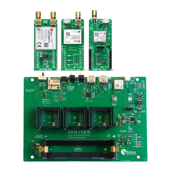
XPLR-HPG-1 - User guide Product description The XPLR-HPG-1 kit offers a flexible evaluation platform with which to explore possible application scenarios using the PointPerfect augmentation service. The platform accesses correction data from satellite broadcasts using an L-band satellite GNSS receiver or through IP connectivity using Wi-Fi or LTE. - Page 6 XPLR-HPG-1 - User guide The board assemblies included in the XPLR-HPG-1 kit are shown in Figure Figure 2: XPLR-HPG-1 board assemblies UBX-23000692 - R01 Product description Page 6 of 37 C1-Public...
-
Page 7: Module Integration
XPLR-HPG-1 - User guide 1.2 Module integration XPLR-HPG-1 integrates the following positioning, cellular, and short-range radio modules: • ZED-F9R high precision dead reckoning module [3]: Global navigation satellite system (GNSS) for high-precision GNSS positioning in challenging environments, including: Multi-band GNSS receiver delivers centimeter-level accuracy Native support for PointPerfect GNSS augmentation service •... -
Page 8: Kit Includes
XPLR-HPG-1 - User guide 1.3 Kit includes Part Description Outline C213 baseboard 1x C213 baseboard with mounted NORA-W106 stand-alone, multiradio module GNSS RTK 2 1x GNSS RTK 2 Click board featuring the ZED-F9R multi-band Click board GNSS module for high-precision GNSS positioning... -
Page 9: Features
GNSS correction data. To use the u-blox software solution available on GitHub, the supplied Click boards, GNSS RTK 2 (ZED F9R), L-band RTK (NEO-D9S), and LTE 2 (LARA-R6), must be plugged into specific MikroBUS connectors on the C213 baseboard to suit the chosen use case configuration. -
Page 10: Case #1: Correction Data Over L-Band Satellite
XPLR-HPG-1 - User guide 1.5.1 Case #1: Correction data over L-band satellite In this scenario, the NEO-D9S module, hosted on the L-band RTK Click board, receives correction data from L-band satellites. NEO-D9S frequency range is 1525 MHz to 1559 MHz. The acquired correction data is transmitted to the NORA-W106 module via the I2C interface. -
Page 11: Case #2: Correction Data Over Cellular
XPLR-HPG-1 - User guide 1.5.2 Case #2: Correction data over Cellular In this scenario, the flow starts when the LARA-R6 modem (hosted on the 4G LTE 2 Click board) acquires correction data and the decryption keys through the cellular network using an MQTT connection. -
Page 12: Case #3: Correction Data Over Wi-Fi
XPLR-HPG-1 - User guide 1.5.3 Case #3: Correction data over Wi-Fi In this scenario, the Wi-Fi MCU NORA-W106 receives the correction data and the decryption keys through a Wi-Fi network using an MQTT connection. Next, the correction data and the decryption keys are forwarded to the ZED-F9R module (hosted on the GNSS RTK 2 Click board) over the I2C interface. -
Page 13: Hardware Description
XPLR-HPG-1 - User guide Hardware description 2.1 C213 baseboard Figure 6 shows the supported physical interfaces and other key components on the C213 baseboard, including: • NORA-W106 stand-alone multiradio module (U1) • 3x mikroBUS™ connectors (MB1, MB2, and MB3) for plugging up to three Mikroe Click boards™, including the GNSS RTK 2, 4G LTE 2, and LBAND RTK Click boards supplied with the kit. -
Page 14: Block Diagram
Figure 7: XPLR-HPG-1 block diagram 2.1.2 Power subsystem XPLR-HPG-1 can be powered by either of the USB-C connectors (UART USB or NORA USB) or the on-board battery, as shown in Figure Figure 8: XPLR-HPG-1 power subsystem UBX-23000692 - R01... - Page 15 LG HG2 INR18650, Samsung INR18650 or other variants. It is advisable to use Li-Ion batteries (rechargeable) Implementing an incompatible cell can seriously damage both the XPLR-HPG-1 kit itself and the battery unit. The battery is not included in the XPLR-HPG-1 kit.
-
Page 16: Nora-W106
XPLR-HPG-1 - User guide 2.1.2.3 Battery protection The evaluation board includes an on-board circuit that protects against overcurrent, over voltage and under voltage. SW1 (battery connect/disconnect switch) switches the battery connection circuit connects and disconnects the battery from the board circuit. -
Page 17: Usb
XPLR-HPG-1 - User guide NORA-W106 pin ESP32-S3 GPIO Function GPIO3 (A) MB1-RX GPIO46 MB1-TX FSPIIO5 / GPIO11 (A) MB2-AN JTAG_TCK / GPIO39 MB2-INT FSPII04 / GPIO10 (A) MB2-PWM SPICLK_P / GPIO47 MB2-RST SPICLK_N / GPIO48 MB2-RX FSPIHD / GPIO33 MB2-TX... -
Page 18: Mikrobus
XPLR-HPG-1 - User guide XPLR-HPG-1 supports an auto reset circuit connected to the BOOT0 and RESET pins of NORA-W106, as shown in Figure 12. This circuit enables programming tools like the to assert the DTR esptool.py and RTS control lines of the USB to Serial converter (CP2102N) and set NORA-W106 on the serial bootloader mode. -
Page 19: Microsd
XPLR-HPG-1 - User guide mikroBUS 1 mikroBUS 2 mikroBUS 3 mikroBUS pin NORA- ESP32-S3 NORA- ESP32-S3 NORA- ESP32-S3 W106 GPIO W106 GPIO W106 GPIO 13 - RX GPIO3 (A) SPICLK_N / GPIO48 14 - TX GPIO46 FSPIHD / GPIO33 15 - INT... -
Page 20: Qwiic
2.1.7 Qwiic XPLR-HPG-1 board has a standard Qwiic connector (J22) for connecting external I2C devices of the Qwiic ecosystem. The interface includes two 2.2 kΩ pull-up resistors referenced to 3.3 V on the SDA and SCL signals. The signals are shown on each mikroBUS slot. -
Page 21: Test Points
XPLR-HPG-1 - User guide NORA-W106 pin Button ESP32-S3 function Function BTN1 / BOOT0 GPIO0 / Boot Connected to BOOT0/GPIO0 pin of the integrated MCU (ESP32-S3) in NORA-W1. Press and hold this button during bootup to put NORA-W1 into bootloader mode. - Page 22 XPLR-HPG-1 - User guide Connector Signal Description Test-point mikroBUS1 PWM output TP16_1 mikroBUS2 Analog input TP4_2 mikroBUS2 Reset output TP6_2 mikroBUS2 SPI_CS SPI Chip Select TP9_2 mikroBUS2 SPI Clock TP27 mikroBUS2 MISO SPI MISO TP29 mikroBUS2 MOSI SPI MOSI TP28 mikroBUS2 +3.3 V DC output...
-
Page 23: Leds
XPLR-HPG-1 - User guide Connector Signal Description Test-point BATTERY Ground BATTERY BATT- Battery negative terminal TP23 BATTERY Battery protection IC input control signal TP55 UART0 TX_CP USB to UART bridge output (UART0 TX) TP46 UART0 RX_CP USB to UART bridge input (UART0 RX) -
Page 24: Rgb Led
XPLR-HPG-1 - User guide 2.1.11 RGB LED XPLR-HPG-1 supports a single RGB LED that is located on the front side edge of the PCB. The circuit connections are shown in Figure Figure 16: RGB LED circuit The LED functions and pin connections to the NORA-W10 module are described in... -
Page 25: Wheel Tick And Direction
XPLR-HPG-1 - User guide 2.1.12 Wheel tick and Direction For automotive applications, Wheel Tick (WT) and Direction (DR) data generated from software or directly from a vehicle sensor can be used to improve Automotive Dead Reckoning (ADR) calculations during instances of weak or no GNSS coverage. WT/DIR data can be communicated from the signal conditioning circuit to the ZED-F9R module through NORA-W1 or directly using an external cable. - Page 26 XPLR-HPG-1 - User guide In the other use scenario shown in Figure 18, WT/DIR data is communicated to ZED-F9R, without an external cable, through the NORA-W1 multiradio module over the UART (microBUS 1 or 2 only) or I2C interface. Figure 18: Wheel tick/ Direction flow I2C or UART scenario...
-
Page 27: Click Boards
WT/DIR-DIR XTAL_32K_P / GPIO15 (A) WT/DIR-WT Table 9: Wheel tick / direction NORA-W106 signals 2.2 Click boards XPLR-HPG-1 comes with three Click boards: • GNSS RTK 2 board featuring the ZED-F9R multi-band GNSS module for high-precision GNSS • LBAND RTK board featuring the NEO-D9S satellite receiver for L-band correction •... -
Page 28: Lband Rtk
XPLR-HPG-1 - User guide 2.2.2 LBAND RTK Figure 21 shows the LBAND RTK Click board hosting the NEO-D9S module and other main components. Figure 21: LBAND RTK Click board 2.2.3 4G LTE 2 Figure 22 shows the 4G LTE Click board hosting the LARA-R600 module and other main components. -
Page 29: Software
3.1 HPG use case examples In addition to the HPG library, the HPG software includes several examples that demonstrate the handling of correction data from the u-blox modules in realistic scenarios and use cases, such as: • Case 1: Correction data over L-band satellite •... -
Page 30: U-Blox Library (Ubxlib)
[14] is hosted on GitHub. The library provides portable, high-level, C libraries that expose the available APIs for handling u-blox short-range radio (Bluetooth/Wi-Fi), positioning (GNSS), and cellular (2G/3G/4G) modules. ubxlib runs on the most common embedded platforms, including u-blox open CPU, stand-alone modules like NORA-B1. -
Page 31: Getting Started
☞ XPLR-HPG-1 does not include a battery or SIM card. As the holders for these components are inaccessible when the kit is fully assembled, you must disassemble the kit to fit them – if needed. See also Inserting the SIM and battery. - Page 32 XPLR-HPG-1 - User guide The following procedure is recommended for fitting these items collectively, but otherwise install only those that are needed for your application design. Make sure that the battery connect switch is OFF (0). Disassemble the Takachi EXPF15-6-11 enclosure as shown in Assembling the enclosure.
-
Page 33: Mounting The Click Boards
XPLR-HPG-1 - User guide 4.4 Mounting the Click boards XPLR-HPG-1 comes pre-assembled in a Takachi EXPF15-6-11 enclosure with all Click boards already mounted on the C213 baseboard. However, if you need to disassemble and reassemble the kit, follow these instructions to mount the Click boards correctly to the C213 baseboard:... -
Page 34: Assembling The Enclosure
XPLR-HPG-1 - User guide 4.5 Assembling the enclosure The C213 baseboard with mounted Click boards is designed to be inserted in a Takachi EXPF15-6-11 enclosure. To assemble the enclosure: Insert the C213 baseboard with all mounted Click boards into the lowest possible position level of the bottom assembly (item 3). -
Page 35: Using The Kit With The Captive Web Portal
Use case #1 Use case To start using the XPLR-HPG-1 kit with the captive portal software: Connect the XPLR-HPG-1 board to a computer using a USB-A to USB-C or USB-C to USB-C cable on the UART J6_2 connector shown in Figure With the kit connected to the computer, NORA-W106 should be available via the “Silicon Labs... -
Page 36: Appendix
XPLR-HPG-1 - User guide Appendix A Glossary Abbreviation Definition GNSS Global Navigation Satellite System GPIO General-purpose input/output High Precision GNSS (IIC) Inter Integrated Circuit Light Emitting Diode Long Term Evolution (4G) Micro Controller Unit MQTT MQ Telemetry Transport Printed Circuit Board... -
Page 37: Ubx-23000692 - R01
[17] Live tracking map using a captive portal - GitHub XPLR-HPG software repository: Readme. [18] m-center, product page [19] u-center, product page ☞ For product change notifications and regular updates of u-blox documentation, register on our website, www.u-blox.com. Revision history Revision Date Name...
Need help?
Do you have a question about the XPLR-HPG-1 and is the answer not in the manual?
Questions and answers