Table of Contents
Advertisement
Quick Links
5000 | 5300 Series
Electric Strikes
Installation & Operating Instructions
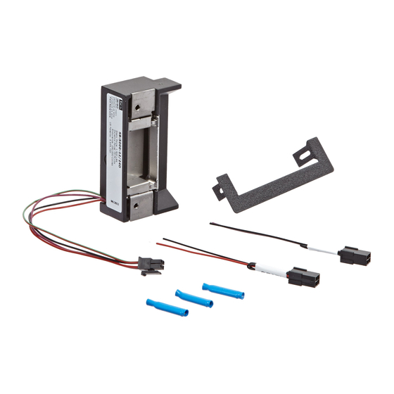
Product Contents
A 5000/5300 Electric Strike Body
B Trim Enhancer (with screws)
C 12 & 24 Volt Pigtails
Electrical Specifications
Electrical Ratings For Solenoid
CONTINUOUS DUTY
12 VDC
Resistance in Ohms
50
Amps
.24
Solenoids are rated at +/- 10% indicated value.
*10% max duty cycle (2 min. max on time) Indoor use only
Minimum Wire Gauge Requirements
12 VDC
200 feet or less
18 gauge
200 – 300 feet
16 gauge
300 – 400 feet
14 gauge
INTERMITTENT DUTY*
24 VDC
12-16 VAC
200
50
.12
.24-.32
SOLENOID VOLTAGE
24 VDC
20 gauge
18 gauge
16 gauge
CAUTION! Before connecting any device at the installation site, verify input voltage using a multimeter.
Many power supplies and low voltage transformers operate at higher levels than listed. Any input voltage
exceeding 10% of the solenoid rating may cause severe damage to the unit and will void the warranty.
Diagram 1: Product Components
A
24 VDC
200
.12
B
C
1 of 4
Advertisement
Table of Contents

Related Manuals for Assa Abloy h.e.s 5000 Series


Summary of Contents for Assa Abloy h.e.s 5000 Series
- Page 1 5000 | 5300 Series Electric Strikes Installation & Operating Instructions Product Contents Diagram 1: Product Components A 5000/5300 Electric Strike Body B Trim Enhancer (with screws) C 12 & 24 Volt Pigtails Electrical Specifications Electrical Ratings For Solenoid CONTINUOUS DUTY INTERMITTENT DUTY* 12 VDC 24 VDC...
- Page 2 Installation Directions Diagram 2 12 V to 24 V Conversion Prepare Strike 1. SELECT the appropriate Plug In Connector that matches system power and electrically connect as illustrated in Diagram 2. FOR 12 V AC/DC OR 16 V AC, the pigtail marked “12 VDC”...
- Page 3 ANSI Metal Jamb Installations 1 -1/4" 1-1/4" [31.8mm] [31.8mm] 501 Faceplate Diagram 5 501 Faceplate 4-7/8" x 1-1/4" Square Corner 4 -7/8" [124mm] 4-7/8" [124mm] 4 -1/8" 3-3/8" 1 -7/16" [104.8mm] [85.7mm] [36.6mm] 11/16" [17.5mm] 3/32" [2.3mm] Aluminum Jamb Installations Aluminum Frame Installations 501A Faceplate 502 Faceplate...
- Page 4 Printed in the U.S.A. Patent pending and/or patent www.assaabloydss.com/patents Copyright © 2023, Hanchett Entry Systems, Inc., an ASSA ABLOY Group company. techsupport.hes@assaabloy.com All rights reserved. Reproduction in whole or in part without the express written 800 626 7590 | hesinnovations.com permission of Hanchett Entry Systems, Inc.
Need help?
Do you have a question about the h.e.s 5000 Series and is the answer not in the manual?
Questions and answers